engine mount CHRYSLER CARAVAN 2002 Service Manual
[x] Cancel search | Manufacturer: CHRYSLER, Model Year: 2002, Model line: CARAVAN, Model: CHRYSLER CARAVAN 2002Pages: 2399, PDF Size: 57.96 MB
Page 19 of 2399
²The use of fuel additives which are now being
sold as octane enhancers is not recommended. Most
of these products contain high concentrations of
methanol. Fuel system damage or vehicle perfor-
mance problems resulting from the use of such fuels
or additives is not the responsibility of
DaimlerChrysler Corporation and may not be covered
under the new vehicle warranty.
NOTE: Intentional tampering with emissions control
systems can result in civil penalties being assessed
against you.
DESCRIPTION - FUEL REQUIREMENTS -
DIESEL ENGINE
WARNING: DO NOT USE ALCOHOL OR GASOLINE
AS A FUEL BLENDING AGENT. THEY CAN BE
UNSTABLE UNDER CERTAIN CONDITIONS AND
HAZARDOUS OR EXPLOSIVE WHEN MIXED WITH
DIESEL FUEL.
Use good quality diesel fuel from a reputable sup-
plier. For most year-round service, number 2 diesel
fuel meeting ASTM specification D-975 will provide
good performance. If the vehicle is exposed to
extreme cold (below -18ÉC/0ÉF) or is required to oper-
ate at colder than normal conditions for prolonged
periods, use climatize No. 2 diesel fuel or dilute the
No. 2 diesel fuel with 50% No. 1 diesel fuel. This will
provide better protection from fuel gelling or wax
plugging of the fuel filters.
Diesel fuel is seldom completely free of water. To
prevent fuel system trouble, including fuel line freez-
ing in winter, drain the accumulated water from the
fuel/water separator using the fuel/water separator
drain provided. If you buy good quality fuel and fol-
low the cold weather advice above, fuel conditioners
should not be required in your vehicle. If available in
your area, a high cetane ªpremiumº diesel fuel may
offer improved cold starting and warm up perfor-
mance.
DESCRIPTION - ENGINE OIL - DIESEL
ENGINES
Use only Diesel Engine Oil meeting standardMIL-
2104Cor API ClassificationCD or higherorCCML
D4, D5.
SAE VISCOSITY GRADE
CAUTION: Low viscosity oils must have the proper
API quality or the CCMC G5 designation.
To assure of properly formulated engine oils, it is
recommended that SAE Grade 10W-40 engine oilsthat meet Chrysler material standard MS-6395, be
used. European Grade 10W-40 oils are also accept-
able.
Oils of the SAE 5W-40 or 8W-80 grade number are
preferred when minimum temperatures consistently
fall below -12ÉC.
FLUID FILL/CHECK
LOCATIONS
DESCRIPTION
The fluid check/fill point locations are located in
each applicable service manual section.
LUBRICATION POINTS
DESCRIPTION
Lubrication point locations are located in each
applicable Sections.
MAINTENANCE SCHEDULES
DESCRIPTION
9Maintenance Schedule Information not included in
this section, is located in the appropriate Owner's
Manual.9
HOISTING
STANDARD PROCEDURE - HOISTING
Refer to Owner's Manual provided with vehicle for
proper emergency jacking procedures.
WARNING: THE HOISTING AND JACK LIFTING
POINTS PROVIDED ARE FOR A COMPLETE VEHI-
CLE. WHEN THE ENGINE OR REAR SUSPENSION
IS REMOVED FROM A VEHICLE, THE CENTER OF
GRAVITY IS ALTERED MAKING SOME HOISTING
CONDITIONS UNSTABLE. PROPERLY SUPPORT OR
SECURE VEHICLE TO HOISTING DEVICE WHEN
THESE CONDITIONS EXIST.
CAUTION: Do not position hoisting device on any
suspension component, including the front suspen-
sion crossmember, the rear leaf springs, and the
rear axle. Do not hoist on the front and rear
bumpers, the lower liftgate crossmember, the lower
radiator crossmember, the down standing flanges
on the sill or the front engine mount.
FOR PROPER HOIST PLACEMENT REFER
TO (Fig. 5).
0 - 6 LUBRICATION & MAINTENANCERS
FLUID TYPES (Continued)
ProCarManuals.com
Page 20 of 2399
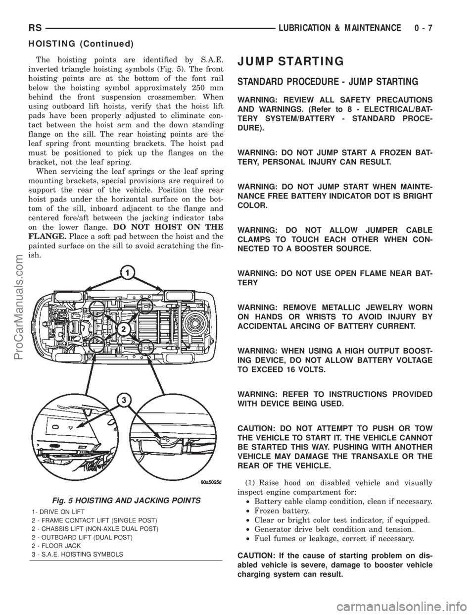
The hoisting points are identified by S.A.E.
inverted triangle hoisting symbols (Fig. 5). The front
hoisting points are at the bottom of the font rail
below the hoisting symbol approximately 250 mm
behind the front suspension crossmember. When
using outboard lift hoists, verify that the hoist lift
pads have been properly adjusted to eliminate con-
tact between the hoist arm and the down standing
flange on the sill. The rear hoisting points are the
leaf spring front mounting brackets. The hoist pad
must be positioned to pick up the flanges on the
bracket, not the leaf spring.
When servicing the leaf springs or the leaf spring
mounting brackets, special provisions are required to
support the rear of the vehicle. Position the rear
hoist pads under the horizontal surface on the bot-
tom of the sill, inboard adjacent to the flange and
centered fore/aft between the jacking indicator tabs
on the lower flange.DO NOT HOIST ON THE
FLANGE.Place a soft pad between the hoist and the
painted surface on the sill to avoid scratching the fin-
ish.JUMP STARTING
STANDARD PROCEDURE - JUMP STARTING
WARNING: REVIEW ALL SAFETY PRECAUTIONS
AND WARNINGS. (Refer to 8 - ELECTRICAL/BAT-
TERY SYSTEM/BATTERY - STANDARD PROCE-
DURE).
WARNING: DO NOT JUMP START A FROZEN BAT-
TERY, PERSONAL INJURY CAN RESULT.
WARNING: DO NOT JUMP START WHEN MAINTE-
NANCE FREE BATTERY INDICATOR DOT IS BRIGHT
COLOR.
WARNING: DO NOT ALLOW JUMPER CABLE
CLAMPS TO TOUCH EACH OTHER WHEN CON-
NECTED TO A BOOSTER SOURCE.
WARNING: DO NOT USE OPEN FLAME NEAR BAT-
TERY
WARNING: REMOVE METALLIC JEWELRY WORN
ON HANDS OR WRISTS TO AVOID INJURY BY
ACCIDENTAL ARCING OF BATTERY CURRENT.
WARNING: WHEN USING A HIGH OUTPUT BOOST-
ING DEVICE, DO NOT ALLOW BATTERY VOLTAGE
TO EXCEED 16 VOLTS.
WARNING: REFER TO INSTRUCTIONS PROVIDED
WITH DEVICE BEING USED.
CAUTION: DO NOT ATTEMPT TO PUSH OR TOW
THE VEHICLE TO START IT. THE VEHICLE CANNOT
BE STARTED THIS WAY. PUSHING WITH ANOTHER
VEHICLE MAY DAMAGE THE TRANSAXLE OR THE
REAR OF THE VEHICLE.
(1) Raise hood on disabled vehicle and visually
inspect engine compartment for:
²Battery cable clamp condition, clean if necessary.
²Frozen battery.
²Clear or bright color test indicator, if equipped.
²Generator drive belt condition and tension.
²Fuel fumes or leakage, correct if necessary.
CAUTION: If the cause of starting problem on dis-
abled vehicle is severe, damage to booster vehicle
charging system can result.
Fig. 5 HOISTING AND JACKING POINTS
1- DRIVE ON LIFT
2 - FRAME CONTACT LIFT (SINGLE POST)
2 - CHASSIS LIFT (NON-AXLE DUAL POST)
2 - OUTBOARD LIFT (DUAL POST)
2 - FLOOR JACK
3 - S.A.E. HOISTING SYMBOLS
RSLUBRICATION & MAINTENANCE0-7
HOISTING (Continued)
ProCarManuals.com
Page 22 of 2399
GROUND CLEARANCE
CAUTION: If vehicle is towed with wheels removed,
install lug nuts to retain brake drums or rotors.
A towed vehicle should be raised until the lifted
wheels are a minimum 100 mm (4 in.) from the
ground. Be sure there is at least 100 mm (4 in.)
clearance between the tail pipe and the ground. If
necessary, remove the wheels from the front end of
the vehicle and lower the front end closer to the
ground, to increase the ground clearance at the rear
of the vehicle. Install lug nuts on wheel attaching
studs to retain brake drums or rotors.
LOCKED VEHICLE TOWING
When a locked vehicle must be towed with the
front wheels on the ground, use a towing dolly or flat
bed hauler.
FLAT TOWING WITH TOW BAR
²Three speed automatic transaxle vehicles can be
flat towed at speeds not to exceed 40 km/h (25 mph)
for not more than 25 km (15 miles). The steering col-
umn must be unlocked and gear selector in neutral.
²Four speed electronic automatic transaxle vehi-
cles can be flat towed at speeds not to exceed 72
km/h (44 mph) for not more than 160 km (100 miles).
The steering column must be unlocked and gear
selector in neutral.
²AWD models should not be flat towed. For addi-
tional information, refer toRECOMMENDED TOW-
ING EQUIPMENTin this section.
FLAT BED TOWING TIE DOWNS
CAUTION: Do not tie vehicle down by attaching
chains or cables to suspension components or
engine mounts, damage to vehicle can result.
The vehicle can be tied to a flat bed device using
the two pair of front slots on the bottom surface of
the rails, behind the front wheels. The two pair of
rear slots on the bottom of the rail between the
bumper extension bolts and on the bottom of the rail
just rearward of the jounce bumper. Vehicles
equipped with a rear sway bar have brackets at this
location.
TOWING ± FRONT WHEEL LIFT
If the vehicle is being towed from the front, when-
ever possible ensure at least 10 inches road clearance
to the tires.
TOWING ± REAR WHEEL LIFT
If a vehicle cannot be towed with the front wheels
lifted, the rear wheels can be lifted provided the fol-
lowing guide lines are observed.
CAUTION: Do not use steering column lock to
secure steering wheel during towing operation.
²On AWD vehicles, all four wheels must be free to
rotate. Use towing dollies at unlifted end of vehicle.
²Unlock steering column and secure steering
wheel in straight ahead position with a clamp device
designed for towing.
²Three speed automatic transaxle vehicles can be
flat towed at speeds not to exceed 40 km/h (25 mph)
for not more than 25 km (15 miles). The steering col-
umn must be unlocked and gear selector in neutral.
²Four speed electronic automatic transaxle vehi-
cles can be flat towed at speeds not to exceed 72
km/h (44 mph) for not more than 160 km (100 miles).
The steering column must be unlocked and gear
selector in neutral.
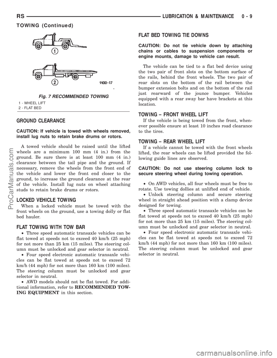
Fig. 7 RECOMMENDED TOWING
1 - WHEEL LIFT
2 - FLAT BED
RSLUBRICATION & MAINTENANCE0-9
TOWING (Continued)
ProCarManuals.com
Page 72 of 2399
THRUST ANGLE
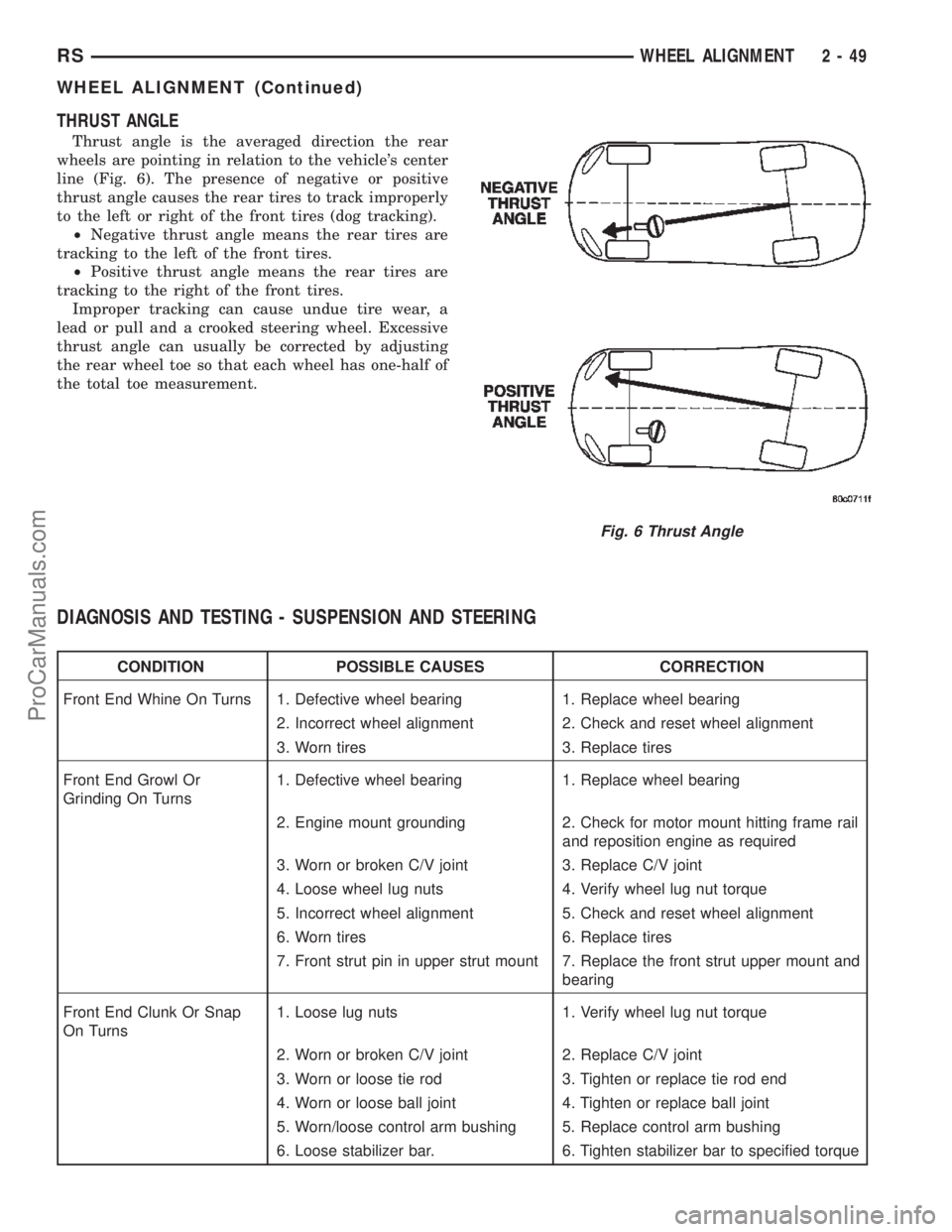
Thrust angle is the averaged direction the rear
wheels are pointing in relation to the vehicle's center
line (Fig. 6). The presence of negative or positive
thrust angle causes the rear tires to track improperly
to the left or right of the front tires (dog tracking).
²Negative thrust angle means the rear tires are
tracking to the left of the front tires.
²Positive thrust angle means the rear tires are
tracking to the right of the front tires.
Improper tracking can cause undue tire wear, a
lead or pull and a crooked steering wheel. Excessive
thrust angle can usually be corrected by adjusting
the rear wheel toe so that each wheel has one-half of
the total toe measurement.
DIAGNOSIS AND TESTING - SUSPENSION AND STEERING
CONDITION POSSIBLE CAUSES CORRECTION
Front End Whine On Turns 1. Defective wheel bearing 1. Replace wheel bearing
2. Incorrect wheel alignment 2. Check and reset wheel alignment
3. Worn tires 3. Replace tires
Front End Growl Or
Grinding On Turns1. Defective wheel bearing 1. Replace wheel bearing
2. Engine mount grounding 2. Check for motor mount hitting frame rail
and reposition engine as required
3. Worn or broken C/V joint 3. Replace C/V joint
4. Loose wheel lug nuts 4. Verify wheel lug nut torque
5. Incorrect wheel alignment 5. Check and reset wheel alignment
6. Worn tires 6. Replace tires
7. Front strut pin in upper strut mount 7. Replace the front strut upper mount and
bearing
Front End Clunk Or Snap
On Turns1. Loose lug nuts 1. Verify wheel lug nut torque
2. Worn or broken C/V joint 2. Replace C/V joint
3. Worn or loose tie rod 3. Tighten or replace tie rod end
4. Worn or loose ball joint 4. Tighten or replace ball joint
5. Worn/loose control arm bushing 5. Replace control arm bushing
6. Loose stabilizer bar. 6. Tighten stabilizer bar to specified torque
Fig. 6 Thrust Angle
RSWHEEL ALIGNMENT2-49
WHEEL ALIGNMENT (Continued)
ProCarManuals.com
Page 73 of 2399
CONDITION POSSIBLE CAUSES CORRECTION
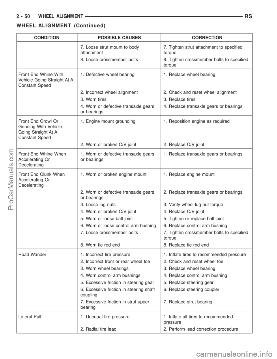
7. Loose strut mount to body
attachment7. Tighten strut attachment to specified
torque
8. Loose crossmember bolts 8. Tighten crossmember bolts to specified
torque
Front End Whine With
Vehicle Going Straight At A
Constant Speed1. Defective wheel bearing 1. Replace wheel bearing
2. Incorrect wheel alignment 2. Check and reset wheel alignment
3. Worn tires 3. Replace tires
4. Worn or defective transaxle gears
or bearings4. Replace transaxle gears or bearings
Front End Growl Or
Grinding With Vehicle
Going Straight At A
Constant Speed1. Engine mount grounding 1. Reposition engine as required
2. Worn or broken C/V joint 2. Replace C/V joint
Front End Whine When
Accelerating Or
Decelerating1. Worn or defective transaxle gears
or bearings1. Replace transaxle gears or bearings
Front End Clunk When
Accelerating Or
Decelerating1. Worn or broken engine mount 1. Replace engine mount
2. Worn or defective transaxle gears
or bearings2. Replace transaxle gears or bearings
3. Loose lug nuts 3. Verify wheel lug nut torque
4. Worn or broken C/V joint 4. Replace C/V joint
5. Worn or loose ball joint 5. Tighten or replace ball joint
6. Worn or loose control arm bushing 6. Replace control arm bushing
7. Loose crossmember bolts 7. Tighten crossmember bolts to specified
torque
8. Worn tie rod end 8. Replace tie rod end
Road Wander 1. Incorrect tire pressure 1. Inflate tires to recommended pressure
2. Incorrect front or rear wheel toe 2. Check and reset wheel toe
3. Worn wheel bearings 3. Replace wheel bearing
4. Worn control arm bushings 4. Replace control arm bushing
5. Excessive friction in steering gear 5. Replace steering gear
6. Excessive friction in steering shaft
coupling6. Replace steering coupler
7. Excessive friction in strut upper
bearing7. Replace strut bearing
Lateral Pull 1. Unequal tire pressure 1. Inflate all tires to recommended
pressure
2. Radial tire lead 2. Perform lead correction procedure
2 - 50 WHEEL ALIGNMENTRS
WHEEL ALIGNMENT (Continued)
ProCarManuals.com
Page 105 of 2399
²Wheel bearings
²Engine
²Transmission
²Exhaust
²Propeller shaft (vibration)
²Vehicle body (drumming)
Driveline module noises are normally divided into
two categories: gear noise or bearing noise. A thor-
ough and careful inspection should be completed to
determine the actual source of the noise before
replacing the driveline module.
The rubber mounting bushings help to dampen-out
driveline module noise when properly installed.
Inspect to confirm that no metal contact exists
between the driveline module case and the body. The
complete isolation of noise to one area requires
expertise and experience. Identifying certain types of
vehicle noise baffles even the most capable techni-
cians. Often such practices as:
²Increase tire inflation pressure to eliminate tire
noise.
²Listen for noise at varying speeds with different
driveline load conditions
²Swerving the vehicle from left to right to detect
wheel bearing noise.
All driveline module assemblies produce noise to a
certain extent. Slight carrier noise that is noticeable
only at certain speeds or isolated situations should be
considered normal. Carrier noise tends to peak at a
variety of vehicle speeds. Noise isNOT ALWAYSan
indication of a problem within the carrier.
TIRE NOISE
Tire noise is often mistaken for driveline module
noise. Tires that are unbalanced, worn unevenly or
are worn in a saw-tooth manner are usually noisy.
They often produce a noise that appears to originate
in the driveline module.
Tire noise changes with different road surfaces, but
driveline module noise does not. Inflate all four tires
with approximately 20 psi (138 kPa) more than the
recommended inflation pressure (for test purposes
only). This will alter noise caused by tires, but will
not affect noise caused by the differential. Rear axle
noise usually ceases when coasting at speeds less
than 30 mph (48 km/h); however, tire noise contin-
ues, but at a lower frequency, as the speed is
reduced.
After test has been completed lower tire pressure
back to recommended pressure.
GEAR NOISE (DRIVE PINION AND RING GEAR)
Abnormal gear noise is rare and is usually caused
by scoring on the ring gear and drive pinion. Scoring
is the result of insufficient or incorrect lubricant in
the carrier housing.Abnormal gear noise can be easily recognized. It
produces a cycling tone that will be very pronounced
within a given speed range. The noise can occur dur-
ing one or more of the following drive conditions:
²Drive
²Road load
²Float
²Coast
Abnormal gear noise usually tends to peak within
a narrow vehicle speed range or ranges. It is usually
more pronounced between 30 to 40 mph (48 to 64
km/h) and 50 to 60 mph (80 to 96 km/h). When objec-
tionable gear noise occurs, note the driving condi-
tions and the speed range.
BEARING NOISE (DRIVE PINION AND
DIFFERENTIAL)
Defective bearings produce a rough growl that is
constant in pitch and varies with the speed of vehi-
cle. Being aware of this will enable a technician to
separate bearing noise from gear noise.
Drive pinion bearing noise that results from defec-
tive or damaged bearings can usually be identified by
its constant, rough sound. Drive pinion front bearing
is usually more pronounced during a coast condition.
Drive pinion rear bearing noise is more pronounced
during a drive condition. The drive pinion bearings
are rotating at a higher rate of speed than either the
differential side bearings or the axle shaft bearing.
Differential side bearing noise will usually produce
a constant, rough sound. The sound is much lower in
frequency than the noise caused by drive pinion bear-
ings.
Bearing noise can best be detected by road testing
the vehicle on a smooth road (black top). However, it
is easy to mistake tire noise for bearing noise. If a
doubt exists, the tire treads should be examined for
irregularities that often causes a noise that resem-
bles bearing noise.
ENGINE AND TRANSMISSION NOISE
Sometimes noise that appears to be in the driv-
eline module assembly is actually caused by the
engine or the transmission. To identify the true
source of the noise, note the approximate vehicle
speed and/or RPM when the noise is most noticeable.
Stop the vehicle next to a flat brick or cement wall
(this will help reflect the sound). Place the transaxle
inNEUTRAL. Accelerate the engine slowly up
through the engine speed that matches the vehicle
speed noted when the noise occurred. If the same
noise is produced, it usually indicates that the noise
is being caused by the engine or transaxle.
3 - 26 REAR DRIVELINE MODULERS
REAR DRIVELINE MODULE (Continued)
ProCarManuals.com
Page 146 of 2399
BRAKE LINES
DESCRIPTION - BRAKE TUBES AND HOSES
The brake tubes are steel with a corrosion-resis-
tant nylon coating applied to the external surfaces.
The flex hoses are made of reinforced rubber with fit-
tings at each end.
The primary and secondary brake tubes leading
from the master cylinder to the ABS ICU Hydraulic
Control Unit (HCU) or the non-ABS junction block
have a special flexible section. This flexible section is
required due to cradle movement while the vehicle is
in motion (The ICU and non-ABS junction block are
mounted to the cradle).If replacement of these
lines is necessary, only the original factory
brake line containing the flexible section must
be used.
OPERATION - BRAKE TUBES AND HOSES
The purpose of the chassis brake tubes and flex
hoses is to transfer the pressurized brake fluid devel-
oped by the master cylinder to the wheel brakes of
the vehicle. The flex hoses are made of rubber to
allow for the movement of the vehicle's suspension.
INSPECTION - BRAKE TUBES AND HOSES
Flexible rubber hose is used at both front brakes
and at the rear axle. Inspection of brake hoses
should be performed whenever the brake system is
serviced and every 7,500 miles or 12 months, which-
ever comes first (every engine oil change). Inspect
hydraulic brake hoses for surface cracking, scuffing,
or worn spots. If the fabric casing of the rubber hose
becomes exposed due to cracks or abrasions in the
rubber hose cover, the hose should be replaced imme-
diately. Eventual deterioration of the hose can take
place with possible burst failure. Faulty installation
can cause twisting, resulting in wheel, tire, or chassis
interference.
The brake tubing should be inspected periodically
for evidence of physical damage or contact with mov-
ing or hot components.
The flexible brake tube sections used on this vehi-
cle in the primary and secondary tubes from the
master cylinder to the ABS hydraulic control unit
connections must also be inspected. This flexible tub-
ing must be inspected for kinks, fraying and contact
with other components or with the body of the vehi-
cle.
BRAKE PADS/SHOES - FRONT
REMOVAL
REMOVAL - FRONT DISC BRAKE SHOES
(DISC/DISC BRAKES)
(1) Raise the vehicle. (Refer to LUBRICATION &
MAINTENANCE/HOISTING - STANDARD PROCE-
DURE).
(2) Remove both front wheel and tire assemblies.
(3) Begin on one side of the vehicle.
(4) Remove the anti-rattle clip from the outboard
side of the caliper and adapter.
(5) Remove the two caliper guide pin bolts.
(6) Remove caliper from caliper adapter and brake
rotor.
CAUTION: Supporting weight of caliper by the flex-
ible brake fluid hose can damage the hose.
(7) Using wire or cord, hang the caliper from the
front strut assembly (Fig. 20). Support the caliper
firmly to prevent weight of caliper from being sup-
ported by the brake fluid hose.
(8) Remove the outboard brake shoe from the cali-
per adapter.
(9) Pull the inboard brake shoe away from the cal-
iper piston until the retaining clip on shoe is free
from the cavity in the caliper piston (Fig. 21).
(10) Repeat the above procedure on other side of
the vehicle.
Fig. 20 Stored Front Disc Brake Caliper
1 - STEERING KNUCKLE
2 - BRAKE FLEX HOSE
3 - CALIPER ASSEMBLY
4 - WIRE HANGER
5 - STRUT ASSEMBLY
RSBRAKES - BASE5-17
ProCarManuals.com
Page 164 of 2399
(3) Install the disc brake caliper over the brake
shoes on the brake caliper adapter.
(4) Align the caliper guide pin bolt holes with the
guide pins. Install the caliper guide pin bolts and
tighten them to a torque of 35 N´m (26 ft. lbs.) (Fig.
51).
(5) Install the tire and wheel assembly. Tighten
the wheel mounting nuts to a torque of 135 N´m (100
ft. lbs.).
(6) Lower the vehicle.
(7) Pump the brake pedal several times before
moving the vehicle to set the shoes to the brake
rotor.
DRUM
REMOVAL
(1) Raise the vehicle. (Refer to LUBRICATION &
MAINTENANCE/HOISTING - STANDARD PROCE-
DURE).
(2) Remove the tire and wheel assembly from the
vehicle
(3) Remove the rear brake shoe adjusting hole
cover plug.
(4) Insert a thin screwdriver into brake adjusting
hole and hold adjusting lever away from notches of
adjusting screw star wheel.
(5) Insert another thin screwdriver into brake
adjusting hole and engage notches of brake adjusting
screw star wheel. Release brake adjustment by pry-
ing down with adjusting tool.
(6) Remove rear brake drum from rear hub/bear-
ing assembly.
NOTE: It may be necessary to insert M8 X 1.25 MM
bolts into the two removal holes on the drum to
force the drum off the hub.
INSTALLATION
(1) Adjust brake shoe assemblies so as not to inter-
fere with brake drum installation.
(2) Install the rear brake drums on the hubs.
(3) Adjust drum brake shoes as necessary per pro-
cedure found in the Adjustment section of this ser-
vice manual group (Refer to 5 - BRAKES/
HYDRAULIC/MECHANICAL/DRUM -
ADJUSTMENTS).
(4) Install wheel and tire assembly.
(5) Tighten the wheel mounting stud nuts in
proper sequence until all nuts are torqued to half
specification. Then repeat the tightening sequence to
the full specified torque of 135 N´m (100 ft. lbs.).
(6) Lower the vehicle.
FLUID
DIAGNOSIS AND TESTING - BRAKE FLUID
CONTAMINATION
Indications of fluid contamination are swollen or
deteriorated rubber parts.
Swollen rubber parts indicate the presence of
petroleum in the brake fluid.
To test for contamination, put a small amount of
drained brake fluid in clear glass jar. If fluid sepa-
rates into layers, there is mineral oil or other fluid
contamination of the brake fluid.
If brake fluid is contaminated, drain and thor-
oughly flush system. Replace master cylinder, propor-
tioning valve, caliper seals, wheel cylinder seals,
Antilock Brake hydraulic unit and all hydraulic fluid
hoses.
STANDARD PROCEDURE - BRAKE FLUID
LEVEL CHECKING
Check master cylinder reservoir fluid level a mini-
mum of twice annually.
Fluid reservoirs are marked with the words FULL
and ADD to indicate proper brake fluid fill level of
the master cylinder.
If necessary, add brake fluid to bring the level to
the bottom of the FULL mark on the side of the mas-
ter cylinder fluid reservoir.
Use only Mopartbrake fluid or equivalent from a
sealed container. Brake fluid must conform to DOT 3
specifications (DOT 4 or DOT 4+ are acceptable).
DO NOTuse brake fluid with a lower boiling
point, as brake failure could result during prolonged
hard braking.
Use only brake fluid that was stored in a tightly-
sealed container.
DO NOTuse petroleum-based fluid because seal
damage will result. Petroleum based fluids would be
items such as engine oil, transmission fluid, power
steering fluid etc.
SPECIFICATIONS
BRAKE FLUID
The brake fluid used in this vehicle must conform
to DOT 3 specifications (DOT 4 and DOT 4+ are
acceptable) and SAE J1703 standards. No other type
of brake fluid is recommended or approved for usage
in the vehicle brake system. Use only MopartBrake
Fluid or equivalent from a tightly sealed container.
CAUTION: Never use reclaimed brake fluid or fluid
from an container which has been left open. An
open container of brake fluid will absorb moisture
from the air and contaminate the fluid.
RSBRAKES - BASE5-35
DISC BRAKE CALIPER GUIDE PINS (Continued)
ProCarManuals.com
Page 165 of 2399
CAUTION: Never use any type of a petroleum-based
fluid in the brake hydraulic system. Use of such
type fluids will result in seal damage of the vehicle
brake hydraulic system causing a failure of the
vehicle brake system. Petroleum based fluids would
be items such as engine oil, transmission fluid,
power steering fluid, etc.
JUNCTION BLOCK
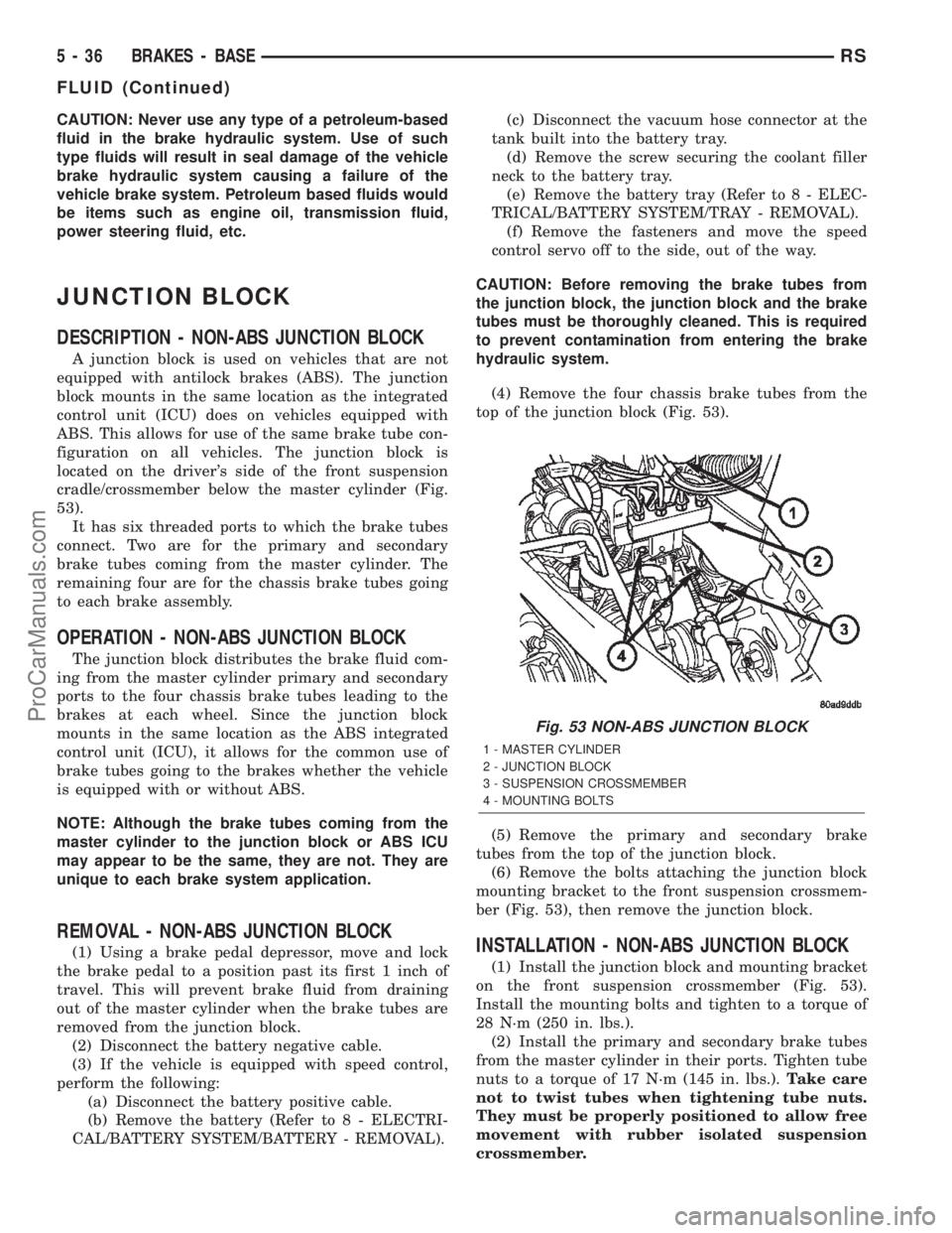
DESCRIPTION - NON-ABS JUNCTION BLOCK
A junction block is used on vehicles that are not
equipped with antilock brakes (ABS). The junction
block mounts in the same location as the integrated
control unit (ICU) does on vehicles equipped with
ABS. This allows for use of the same brake tube con-
figuration on all vehicles. The junction block is
located on the driver's side of the front suspension
cradle/crossmember below the master cylinder (Fig.
53).
It has six threaded ports to which the brake tubes
connect. Two are for the primary and secondary
brake tubes coming from the master cylinder. The
remaining four are for the chassis brake tubes going
to each brake assembly.
OPERATION - NON-ABS JUNCTION BLOCK
The junction block distributes the brake fluid com-
ing from the master cylinder primary and secondary
ports to the four chassis brake tubes leading to the
brakes at each wheel. Since the junction block
mounts in the same location as the ABS integrated
control unit (ICU), it allows for the common use of
brake tubes going to the brakes whether the vehicle
is equipped with or without ABS.
NOTE: Although the brake tubes coming from the
master cylinder to the junction block or ABS ICU
may appear to be the same, they are not. They are
unique to each brake system application.
REMOVAL - NON-ABS JUNCTION BLOCK
(1) Using a brake pedal depressor, move and lock
the brake pedal to a position past its first 1 inch of
travel. This will prevent brake fluid from draining
out of the master cylinder when the brake tubes are
removed from the junction block.
(2) Disconnect the battery negative cable.
(3) If the vehicle is equipped with speed control,
perform the following:
(a) Disconnect the battery positive cable.
(b) Remove the battery (Refer to 8 - ELECTRI-
CAL/BATTERY SYSTEM/BATTERY - REMOVAL).(c) Disconnect the vacuum hose connector at the
tank built into the battery tray.
(d) Remove the screw securing the coolant filler
neck to the battery tray.
(e) Remove the battery tray (Refer to 8 - ELEC-
TRICAL/BATTERY SYSTEM/TRAY - REMOVAL).
(f) Remove the fasteners and move the speed
control servo off to the side, out of the way.
CAUTION: Before removing the brake tubes from
the junction block, the junction block and the brake
tubes must be thoroughly cleaned. This is required
to prevent contamination from entering the brake
hydraulic system.
(4) Remove the four chassis brake tubes from the
top of the junction block (Fig. 53).
(5) Remove the primary and secondary brake
tubes from the top of the junction block.
(6) Remove the bolts attaching the junction block
mounting bracket to the front suspension crossmem-
ber (Fig. 53), then remove the junction block.INSTALLATION - NON-ABS JUNCTION BLOCK
(1) Install the junction block and mounting bracket
on the front suspension crossmember (Fig. 53).
Install the mounting bolts and tighten to a torque of
28 N´m (250 in. lbs.).
(2) Install the primary and secondary brake tubes
from the master cylinder in their ports. Tighten tube
nuts to a torque of 17 N´m (145 in. lbs.).Take care
not to twist tubes when tightening tube nuts.
They must be properly positioned to allow free
movement with rubber isolated suspension
crossmember.
Fig. 53 NON-ABS JUNCTION BLOCK
1 - MASTER CYLINDER
2 - JUNCTION BLOCK
3 - SUSPENSION CROSSMEMBER
4 - MOUNTING BOLTS
5 - 36 BRAKES - BASERS
FLUID (Continued)
ProCarManuals.com
Page 166 of 2399

(3) Install the four chassis brake tubes into the
outlet ports of the junction block. Tighten all 6 tube
nuts to a torque of 17 N´m (145 in. lbs.).
(4) If the vehicle is equipped with speed control,
perform the following:
(a) Install the speed control servo with its
mounting nuts.
(b) Connect the wiring harness to the speed con-
trol servo.
(c) Install the battery tray (Refer to 8 - ELEC-
TRICAL/BATTERY SYSTEM/TRAY - INSTALLA-
TION).
(d) Install the screw securing the coolant filler
neck to the battery tray.
(e) Reconnect the vacuum hose connector at the
tank built into the battery tray.
(f) Install the battery (Refer to 8 - ELECTRI-
CAL/BATTERY SYSTEM/BATTERY - INSTALLA-
TION).
(g) Install the battery shield.
(5) Remove the brake pedal holder.
(6) Connect negative cable back on negative post of
the battery.
(7) Bleed the brake system thoroughly to ensure
that all air has been expelled from the hydraulic sys-
tem. (Refer to 5 - BRAKES - STANDARD PROCE-
DURE).
(8) Road test the vehicle to verify proper operation
of the brake system.
MASTER CYLINDER
DESCRIPTION
DESCRIPTION
The master cylinder is located on the power brake
booster in the engine compartment on the driver's
side (Fig. 54). This vehicle uses 3 different master
cylinders. Master cylinder usage depends on what
type of brake system the vehicle is equipped with.
CAUTION: Master cylinders are not interchangeable
between systems. Performance and stopping dis-
tance issues will result if the incorrect master cyl-
inder is installed on the vehicle.
For information on master cylinder application,
bore and type, view the following table:
BRAKE SYSTEMMASTER CYLINDER
BORE/TYPE
Disc/Drum - ABS23.8 mm (15/16 in.)
Conventional
Compensating Port
Disc/Drum - Non-ABS23.8 mm (15/16 in.)
Conventional
Compensating Port
Disc/Disc - ABS27.0 mm (1-1/16 in.)
Conventional
Compensating Port
Disc/Disc ABS With
Traction Control27.0 mm (1-1/16 in.) Dual
Center Port
CAUTION: When replacing a master cylinder, be
sure to use the correct master cylinder for the type
of brake system the vehicle is equipped with.
The body of the master cylinder is an anodized alu-
minum casting. It has a machined bore to accept the
master cylinder pistons and threaded ports with
seats for the hydraulic brake line connections.
The brake fluid reservoir is mounted on the top of
the master cylinder. It is made of a see-through
polypropylene type plastic for easy fluid level view-
ing. A brake fluid level switch is attached to the
brake fluid reservoir.
The master cylinder is not a repairable component
and must be replaced if diagnosed to be functioning
improperly. The brake fluid reservoir and brake fluid
level switch can be replaced separately.
Fig. 54 Master Cylinder And Booster Location
1 - MASTER CYLINDER
2 - POWER BRAKE BOOSTER
RSBRAKES - BASE5-37
JUNCTION BLOCK (Continued)
ProCarManuals.com