engine mount CHRYSLER CARAVAN 2002 Owner's Manual
[x] Cancel search | Manufacturer: CHRYSLER, Model Year: 2002, Model line: CARAVAN, Model: CHRYSLER CARAVAN 2002Pages: 2399, PDF Size: 57.96 MB
Page 184 of 2399

(12) Connect wiring harness connector to brake
fluid level switch in the master cylinder fluid reser-
voir (Fig. 77).
(13) Connect primary and secondary brake tubes
to ABS ICU or non-ABS junction block (Fig. 78).
Tighten the tube nuts to 17 N´m (145 in lbs.).
(14) Install wiper module (unit). (Refer to 8 -
ELECTRICAL/WIPERS/WASHERS/WIPER MOD-
ULE - INSTALLATION)
(15) If equipped with speed control, install speed
control servo and connect wiring connector. Tighten
the mounting nuts to a torque of 14 N´m (124 in.
lbs.).
(16) Install the battery tray. Install the two nuts
and one bolt attaching the battery tray to the vehicle.
Tighten the bolt and nuts to a torque of 14 N´m (124
in. lbs.).
(17) If vehicle is equipped with speed control, con-
nect the servo vacuum hose to the vacuum tank on
the battery tray.
(18) Install the air inlet resonator and hoses as an
assembly on the throttle body and air cleaner hous-
ing. Securely tighten hose clamp at air cleaner hous-
ing and throttle body.
(19) Secure the engine coolant filler neck to the
battery tray with its mounting screw.
(20) Install the battery, clamp and mounting nut.
(21) Install the positive battery cable on the bat-
tery.
(22) Install the negative battery cable on the bat-
tery.
(23) Install the battery thermal guard shield.
(24) Bleed the base brakes as necessary. (Refer to
5 - BRAKES - STANDARD PROCEDURE)
(25) Road test vehicle to ensure operation of the
brakes.
INSTALLATION - RHD
(1) Position power brake booster on dash panel
using the reverse procedure of its removal (Fig. 86).
(2) Below instrument panel, first install the two
upper nuts mounting the booster to the dash panel,
drawing it into place, then install the two lower
mounting nuts. Tighten the mounting nuts to a
torque of 29 N´m (250 in. lbs.).
(3) Using lubriplate, or equivalent, coat the sur-
face of the brake pedal torque shaft pin where it con-
tacts the booster input rod.
CAUTION: When installing the brake pedal torque
shaft pin on the power brake booster input rod, do
not re-use the old retaining clip.
(4) Install booster input rod on brake pedal torque
shaft pin and install a NEW retaining clip (Fig. 89).
(5) Install booster input rod trim cover.(6) Connect vacuum hose to check valve on power
brake booster.
CAUTION: The master cylinder (and its rear seal) is
used to create the seal for holding vacuum in the
vacuum booster. The vacuum seal on the master
cylinder MUST be replaced with a NEW seal when-
ever the master cylinder is removed from the vac-
uum booster.
CAUTION: When removing the vacuum seal from
the master cylinder, do not use a sharp tool.
(7) Using a soft tool such as a trim stick, remove
the vacuum seal from the master cylinder mounting
flange.
(8) Install a NEW vacuum seal on rear mounting
flange of the master cylinder (Fig. 90).
(9) Position master cylinder on studs of booster,
aligning push rod on booster with master cylinder
piston.
(10) Install the two nuts mounting the master cyl-
inder to the booster (Fig. 83). Tighten both mounting
nuts to a torque of 25 N´m (225 in. lbs.).
(11) Connect wiring harness connector to brake
fluid level switch in the master cylinder fluid reser-
voir (Fig. 82).
(12) If the vehicle is equipped with the 2.5L diesel
engine, install the coolant recovery pressure con-
tainer and bracket. (Refer to 7 - COOLING/ENGINE/
COOLANT RECOVERY PRESS CONTAINER -
INSTALLATION)
(13) If equipped with speed control, install speed
control servo and connect wiring connector. Tighten
Fig. 89 Retaining Pin Installed On Brake Pedal Pin
(Typical)
1 - BRAKE PEDAL
2 - RETAINING CLIP
3 - BOOSTER INPUT ROD
RSBRAKES - BASE5-55
POWER BRAKE BOOSTER (Continued)
ProCarManuals.com
Page 230 of 2399
(7) Using a brake pedal depressor, move and lock
the brake pedal to a position past the first inch of
pedal travel.This will prevent brake fluid from
draining out of the master cylinder once the
brake tubes are removed from the HCU.
CAUTION: Do not apply a 12±volt power source to
any terminals of the 24-way CAB connector when
disconnected.
(8) Disconnect the wiring harness connector from
the speed control servo.
(9) Remove the speed control servo mounting nuts
and move the servo out of the way.
(10) Disconnect the 24±way connector from the
CAB. To disconnect the 24±way connector, grasp the
lock on the 24±way connector and pull it as far up as
possible. This will unlock the 24±way connector from
the socket on the CAB.
CAUTION: Before removing the brake tubes from
the HCU, the HCU must be thoroughly cleaned. This
must be done to prevent dirt particles from falling
into the ports of HCU or entering the brake tubes.
(11) Thoroughly clean all surfaces of the ICU and
brake tube nuts. Use only a solvent such as Mopart
Brake Parts Cleaner or equivalent to clean the ICU.
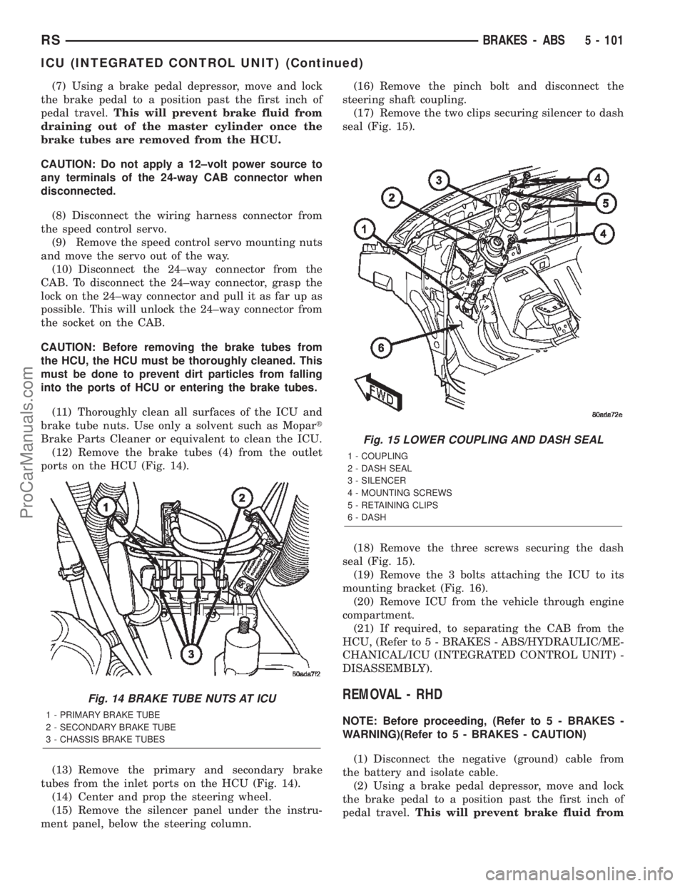
(12) Remove the brake tubes (4) from the outlet
ports on the HCU (Fig. 14).
(13) Remove the primary and secondary brake
tubes from the inlet ports on the HCU (Fig. 14).
(14) Center and prop the steering wheel.
(15) Remove the silencer panel under the instru-
ment panel, below the steering column.(16) Remove the pinch bolt and disconnect the
steering shaft coupling.
(17) Remove the two clips securing silencer to dash
seal (Fig. 15).
(18) Remove the three screws securing the dash
seal (Fig. 15).
(19) Remove the 3 bolts attaching the ICU to its
mounting bracket (Fig. 16).
(20) Remove ICU from the vehicle through engine
compartment.
(21) If required, to separating the CAB from the
HCU, (Refer to 5 - BRAKES - ABS/HYDRAULIC/ME-
CHANICAL/ICU (INTEGRATED CONTROL UNIT) -
DISASSEMBLY).
REMOVAL - RHD
NOTE: Before proceeding, (Refer to 5 - BRAKES -
WARNING)(Refer to 5 - BRAKES - CAUTION)
(1) Disconnect the negative (ground) cable from
the battery and isolate cable.
(2) Using a brake pedal depressor, move and lock
the brake pedal to a position past the first inch of
pedal travel.This will prevent brake fluid from
Fig. 14 BRAKE TUBE NUTS AT ICU
1 - PRIMARY BRAKE TUBE
2 - SECONDARY BRAKE TUBE
3 - CHASSIS BRAKE TUBES
Fig. 15 LOWER COUPLING AND DASH SEAL
1 - COUPLING
2 - DASH SEAL
3 - SILENCER
4 - MOUNTING SCREWS
5 - RETAINING CLIPS
6 - DASH
RSBRAKES - ABS5 - 101
ICU (INTEGRATED CONTROL UNIT) (Continued)
ProCarManuals.com
Page 238 of 2399
DIAGNOSIS AND TESTING
DIAGNOSIS AND TESTING - CLUTCH SYSTEM
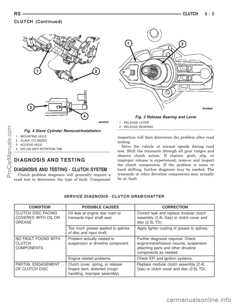
Clutch problem diagnosis will generally require a
road test to determine the type of fault. Componentinspection will then determine the problem after road
testing.
Drive the vehicle at normal speeds during road
test. Shift the transaxle through all gear ranges and
observe clutch action. If chatter, grab, slip, or
improper release is experienced, remove and inspect
the clutch components. If the problem is noise or
hard shifting, further diagnosis may be needed. The
transaxle or other driveline components may actually
be at fault.
SERVICE DIAGNOSIS - CLUTCH GRAB/CHATTER
CONDITION POSSIBLE CAUSES CORRECTION
CLUTCH DISC FACING
COVERED WITH OIL OR
GREASEOil leak at engine rear main or
transaxle input shaft seal.Correct leak and replace modular clutch
assembly (2.4L Gas) or clutch cover and
disc (2.5L TD).
Too much grease applied to splines
of disc and input shaft.Apply lighter coating of grease to splines.
NO FAULT FOUND WITH
CLUTCH
COMPONENTSProblem actually related to
suspension or driveline component.Further diagnosis required. Check
engine/transmission mounts, suspension
attaching parts and other driveline
components as needed.
Engine related problems. Check EFI and ignition systems.
PARTIAL ENGAGEMENT
OF CLUTCH DISCClutch cover, spring, or release
fingers bent, distorted (rough
handling, improper assembly).Replace modular clutch assembly (2.4L
Gas) or clutch cover and disc (2.5L TD).
Fig. 4 Slave Cylinder Removal/Installation
1 - MOUNTING HOLE
2 - SLAVE CYLINDER
3 - ACCESS HOLE
4 - NYLON ANTI-ROTATION TAB
Fig. 5 Release Bearing and Lever
1 - RELEASE LEVER
2 - RELEASE BEARING
RSCLUTCH6-3
CLUTCH (Continued)
ProCarManuals.com
Page 239 of 2399
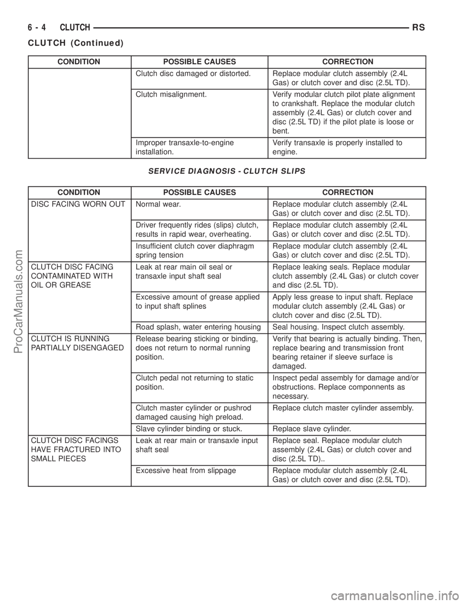
CONDITION POSSIBLE CAUSES CORRECTION
Clutch disc damaged or distorted. Replace modular clutch assembly (2.4L
Gas) or clutch cover and disc (2.5L TD).
Clutch misalignment. Verify modular clutch pilot plate alignment
to crankshaft. Replace the modular clutch
assembly (2.4L Gas) or clutch cover and
disc (2.5L TD) if the pilot plate is loose or
bent.
Improper transaxle-to-engine
installation.Verify transaxle is properly installed to
engine.
SERVICE DIAGNOSIS - CLUTCH SLIPS
CONDITION POSSIBLE CAUSES CORRECTION
DISC FACING WORN OUT Normal wear. Replace modular clutch assembly (2.4L
Gas) or clutch cover and disc (2.5L TD).
Driver frequently rides (slips) clutch,
results in rapid wear, overheating.Replace modular clutch assembly (2.4L
Gas) or clutch cover and disc (2.5L TD).
Insufficient clutch cover diaphragm
spring tensionReplace modular clutch assembly (2.4L
Gas) or clutch cover and disc (2.5L TD).
CLUTCH DISC FACING
CONTAMINATED WITH
OIL OR GREASELeak at rear main oil seal or
transaxle input shaft sealReplace leaking seals. Replace modular
clutch assembly (2.4L Gas) or clutch cover
and disc (2.5L TD).
Excessive amount of grease applied
to input shaft splinesApply less grease to input shaft. Replace
modular clutch assembly (2.4L Gas) or
clutch cover and disc (2.5L TD).
Road splash, water entering housing Seal housing. Inspect clutch assembly.
CLUTCH IS RUNNING
PARTIALLY DISENGAGEDRelease bearing sticking or binding,
does not return to normal running
position.Verify that bearing is actually binding. Then,
replace bearing and transmission front
bearing retainer if sleeve surface is
damaged.
Clutch pedal not returning to static
position.Inspect pedal assembly for damage and/or
obstructions. Replace componnents as
necessary.
Clutch master cylinder or pushrod
damaged causing high preload.Replace clutch master cylinder assembly.
Slave cylinder binding or stuck. Replace slave cylinder.
CLUTCH DISC FACINGS
HAVE FRACTURED INTO
SMALL PIECESLeak at rear main or transaxle input
shaft sealReplace seal. Replace modular clutch
assembly (2.4L Gas) or clutch cover and
disc (2.5L TD)..
Excessive heat from slippage Replace modular clutch assembly (2.4L
Gas) or clutch cover and disc (2.5L TD).
6 - 4 CLUTCHRS
CLUTCH (Continued)
ProCarManuals.com
Page 241 of 2399
DIAGNOSIS AND TESTING - CLUTCH COVER
AND DISC RUNOUT
Check condition of the clutch cover before installa-
tion. A warped cover or diaphragm spring will cause
grab and/or incomplete release or engagement. Use
care when handling the clutch assembly. Impact can
distort the cover, diaphragm spring, and release fin-
gers.
DIAGNOSIS AND TESTING - CLUTCH CHATTER
COMPLAINTS
For all clutch chatter complaints, perform the fol-
lowing:
(1) Check for loose, misaligned, or broken engine
and transmission mounts. If present, they should be
corrected at this time. Test vehicle for chatter. If
chatter is gone, there is no need to go any further.
(2) If chatter persists, check hydraulic clutch
release system is functioning properly.
(3) Check for loose connections in drivetrain. Cor-
rect any problems and determine if clutch chatter
complaints have been satisfied. If not:
(a) Remove transaxle.
(b) Check to see if the release bearing is sticky
or binding. Replace bearing, if needed.
(c) Check linkage for excessive wear on the pivot
stud and fork fingers. Replace all worn parts.
(d) Check clutch assembly for contamination
(dirt, oil). Replace clutch assembly, if required.
(e) Check to see if the clutch disc hub splines
are damaged. Replace with new clutch assembly, if
necessary.
(f) Check input shaft splines for damage.
Replace, if necessary.
(g) Check for uneven wear on clutch fingers.
(h) Check for broken clutch cover diaphragm
spring fingers. Replace with new clutch assembly,
if necessary.
SPECIAL TOOLS - T850 TRANSAXLE
CLUTCH RELEASE LEVER AND
BEARING
REMOVAL
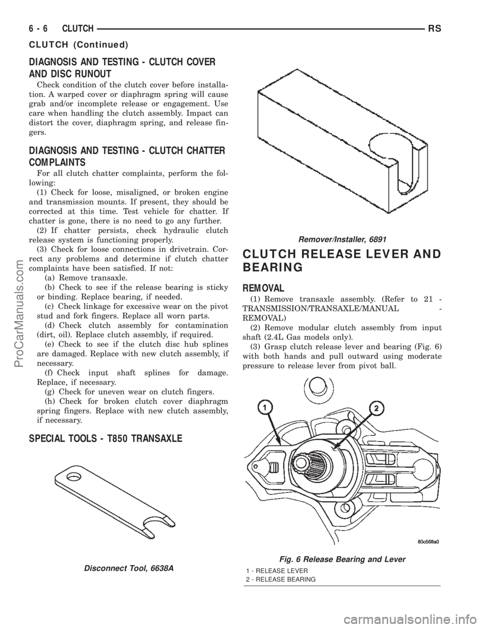
(1) Remove transaxle assembly. (Refer to 21 -
TRANSMISSION/TRANSAXLE/MANUAL -
REMOVAL)
(2) Remove modular clutch assembly from input
shaft (2.4L Gas models only).
(3) Grasp clutch release lever and bearing (Fig. 6)
with both hands and pull outward using moderate
pressure to release lever from pivot ball.
Disconnect Tool, 6638A
Remover/Installer, 6891
Fig. 6 Release Bearing and Lever
1 - RELEASE LEVER
2 - RELEASE BEARING
6 - 6 CLUTCHRS
CLUTCH (Continued)
ProCarManuals.com
Page 252 of 2399

With engine not running, remove radiator pressure
cap and wipe the radiator filler neck sealing seat
clean. The radiator should be full.
Attach the Cooling System Tester 7700 or equiva-
lent to the radiator, as shown in (Fig. 4) and apply
104 kPa (15 psi) pressure. If the pressure drops more
than 13.8 kPa (2 psi) in 2 minutes, inspect all points
for external leaks.
All radiator and heater hoses should be shaken
while at 104 kPa (15 psi), since some leaks occur only
while driving due to engine movement.If there are no external leaks, after the gauge dial
shows a drop in pressure, detach the tester. Start
engine and run until the thermostat opens, allowing
the coolant to expand. Reattach the cooling system
tester. If the needle on the dial fluctuates it indicates
a combustion leak, usually a head gasket leak.
WARNING: WITH TOOL IN PLACE, PRESSURE WILL
BUILD UP FAST. EXCESSIVE PRESSURE BUILT UP,
BY CONTINUOUS ENGINE OPERATION, MUST BE
RELEASED TO A SAFE PRESSURE POINT. NEVER
PERMIT PRESSURE TO EXCEED 138 kPa (20 psi).
If the needle on the dial does not fluctuate, raise
the engine rpm a few times. If an abnormal amount
of coolant or steam emits from the tailpipe, it may
indicate a coolant leak caused by a faulty head gas-
ket, cracked engine block, or cracked cylinder head.
There may be internal leaks that can be deter-
mined by removing the oil dipstick. If water globules
appear intermixed with the oil it will indicate an
internal leak in the engine. If there is an internal
leak, the engine must be disassembled for repair.
DIAGNOSIS AND TESTING - COOLING SYSTEM
FLOW CHECK
To determine whether coolant is flowing through
the cooling system, use one of the following proce-
dures:
PREFERRED METHOD
WARNING: DO NOT REMOVE THE COOLING SYS-
TEM PRESSURE CAP OR ANY HOSE WITH THE
SYSTEM HOT AND UNDER PRESSURE BECAUSE
SERIOUS BURNS FROM COOLANT CAN OCCUR.
²Remove pressure cap when engine is cold.
Remove small amount of coolant. Idle engine until
thermostat opens. You should observe coolant flow
while looking down the filler neck. Once flow is
detected install the pressure cap. Replace removed
coolant into coolant recovery container.
ALTERNATIVE METHOD
²If engine is cold, idle engine until normal oper-
ating temperature is reached. Feel the upper radiator
hose. If it is hot, coolant is circulating.
Fig. 3 Hose Clamp Tool
1 - HOSE CLAMP TOOL 6094
2 - HOSE CLAMP
Fig. 4 Pressure Testing
RSCOOLING7-3
COOLING (Continued)
ProCarManuals.com
Page 255 of 2399

SPECIFICATIONS
COOLING SYSTEM CAPACITY
Engine Coolant Capacity*
2.4L 10.7 L (11.4 qts.)
3.3/3.8L (without
rear heater)12.6 L (13.4 qts.)
3.3/3.8L (with rear
heater)15.4 L (16.3 qts.)
*Includes Heater and Coolant Recovery System
ACCESSORY DRIVE BELT TENSION
ACCESSORY
DRIVE BELTTENSION
2.4L ENGINE
Air Conditioning
Compressor/
GeneratorDynamic Tensioner
Power
SteeringNew
Belt534 - 756 N
183 - 218 Hz
(120 - 170
lbs.)
Used
Belt*356 - 534 N
150 - 183 Hz
(80 - 120 lbs)
*Belt is considered used after 15 minutes of run-in
time
3.3/3.8L ENGINES
Air Conditioning
CompressorDynamic
Tensioner
Generator/Water
Pump/Power
Steering
TORQUE
DESCRIPTION N´mFt.
Lbs.In.
Lbs.
Accessory Drive Belt Tensioner
Assembly (3.3/3.8L)ÐBolt28 Ð 250
Engine Coolant Temperature
Sensor
(2.4 & 3.3/3.8L) 7 Ð 60
Generator & A/C Compressor Drive
Belt Tensioner Assembly (2.4L)Ð
Bolt54 40 Ð
Coolant Outlet Connector/
Thermostat Housing
(2.4 & 3.3/3.8L)ÐBolts 28 Ð 250
Water Pump
(2.4 & 3.3/3.8L)ÐBolts 12 Ð 105
Water Pump Inlet Tube (2.4L)Ð
Bolts12 Ð 105
Water Pump Inlet Tube (3.3/3.8L)Ð
Bolts28 Ð 250
Water Pump Pulley (3.3/3.8L)Ð
Bolts28 Ð 250
Radiator to A/C CondenserÐ
Screws5Ð45
Radiator FanÐScrews 5 Ð 45
Radiator Mounting (Upper
Bracket)ÐNuts12 Ð 105
7 - 6 COOLINGRS
COOLING (Continued)
ProCarManuals.com
Page 268 of 2399

CLEANING
Drain cooling system and refill with clean water.
Refer to drain and fill procedures in this section. Run
engine with radiator cap installed until upper radia-
tor hose is hot. Stop engine and drain water from
system. If water is dirty; fill, run, and drain system
again, until water runs clear. Refill cooling system
with a 50/50 mixture of the recommended ethylene
glycol and distilled water (Refer to LUBRICATION &
MAINTENANCE/FLUID TYPES - DESCRIPTION).
INSPECTION
After performing a cleaning/flush procedure,
inspect all hoses, clamps and connections for deterio-
ration and leaks. Inspect radiator and heater core for
leaks.
COOLANT
DIAGNOSIS AND TESTING - COOLANT
CONCENTRATION TESTING
Coolant concentration should be checked when any
additional coolant was added to system or after a
coolant drain, flush and refill. The coolant mixture
offers optimum engine cooling and protection against
corrosion when mixed to a freeze point of -37ÉC
(-34ÉF) to -46ÉC (-50ÉF). The use of a hydrometer or a
refractometer can be used to test coolant concentra-
tion.
A hydrometer will test the amount of glycol in a
mixture by measuring the specific gravity of the mix-
ture. The higher the concentration of ethylene glycol,
the larger the number of balls that will float, and
Fig. 1 Temperature Gauge Indications
RSENGINE7-19
ENGINE (Continued)
ProCarManuals.com
Page 269 of 2399

higher the freeze protection (up to a maximum of
60% by volume glycol).
A refractometer (Special Tool 8286)(Refer to 7 -
COOLING - SPECIAL TOOLS) will test the amount
of glycol in a coolant mixture by measuring the
amount a beam of light bends as it passes through
the fluid.
Some coolant manufactures use other types of gly-
cols into their coolant formulations. Propylene glycol
is the most common new coolant. However, propylene
glycol based coolants do not provide the same freez-
ing protection and corrosion protection and is not rec-
ommended.
CAUTION: Do not mix types of coolantÐcorrosion
protection will be severely reduced.
STANDARD PROCEDURE - COOLANT SERVICE
For engine coolant recommended service schedule,
(Refer to LUBRICATION & MAINTENANCE/MAIN-
TENANCE SCHEDULES - DESCRIPTION).
COOLANT RECOVERY
CONTAINER
DESCRIPTION
The coolant recovery/reserve system cotainer is
mounted in the engine compartment (Fig. 2). The
container is made of plastic.
OPERATION
The coolant recovery system works with the radia-
tor pressure cap to use thermal expansion and con-
traction of the coolant to keep the coolant free of
trapped air. Provides a convenient and safe method
for checking coolant level and adjusting level at
atmospheric pressure without removing the radiator
pressure cap. It also provides some reserve coolant to
cover deaeration, evaporation, or boiling losses.
DIAGNOSIS AND TESTING - COOLANT
RECOVERY SYSTEM
The cooling system is closed and designed to main-
tain coolant level to the top of the radiator.
(1) With the engineoffand cooling systemnot
under pressure, drain several ounces of coolant from
the radiator draincock while observing the coolant
recovery container. Coolant level in the container
should drop.
(2) Remove the radiator pressure cap. The coolant
level should be full to the top radiator neck. If not,and the coolant level in the container is at or above
the MIN mark, there is an air leak in the coolant
recovery system.
(3) Check hose and hose connections to the con-
tainer, radiator filler neck or the pressure cap seal to
the radiator filler neck for leaks.
REMOVAL
(1) Raise the vehicle on hoist.
(2) Remove the lower attaching screws (Fig. 2).
(3) Lower the vehicle.
(4) Remove the upper attaching screw (Fig. 2).
(5) Disconnect recovery hose from container (Fig.
2).
(6) Remove the recovery container.
INSTALLATION
(1) Connect the recovery hose to container (Fig. 2).
(2) Position the recovery container on the frame
rail (Fig. 2).
(3) Install the upper attaching screw and tighten
to 7 N´m (60 in. lbs.) (Fig. 2).
(4) Raise the vehicle on hoist.
(5) Install the lower attaching screws and tighten
to 8.5 N´m (75 in. lbs.) (Fig. 2).
(6) Lower the vehicle.
(7) Add coolant to container as necessary. (Refer to
7 - COOLING - STANDARD PROCEDURE)
Fig. 2 Coolant Recovery Container
1 - UPPER BOLT ATTACHING TO BATTERY TRAY
2 - COOLANT RECOVERY CONTAINER
3 - UPPER BOLT
4 - HOSE
5 - LOWER BOLT (QTY. 2)
6 - LEFT SIDE FRAME RAIL
7 - 20 ENGINERS
COOLANT (Continued)
ProCarManuals.com
Page 270 of 2399
ENGINE BLOCK HEATER
DESCRIPTION
The engine block heater is available as an optional
accessory on all models. The heater is operated by
ordinary house current (110 Volt A.C.) through a
power cord located behind the radiator grille. This
provides easier engine starting and faster warm-up
when vehicle is operated in areas having extremely
low temperatures. The heater is mounted in a core
hole (in place of a core hole plug) in the engine block,
with the heating element immersed in coolant.
OPERATION
The block heater element is submerged in the cool-
ing system's coolant. When electrical power (110 volt
A.C.) is applied to the element, it creates heat. This
heat is transferred to the engine coolant. This pro-
vides easier engine starting and faster warm-up
when vehicle is operated in areas having extremely
low temperatures.
DIAGNOSIS AND TESTING - ENGINE BLOCK
HEATER TESTING
If unit does not operate, trouble can be in either
the power cord or the heater element. Test power
cord for continuity with a 110-volt voltmeter or 110-
volt test light; test heater element continuity with an
ohmmeter or 12-volt test light.
REMOVAL
(1) Drain coolant from radiator and cylinder block.
(Refer to 7 - COOLING - STANDARD PROCEDURE)
(2) Disconnect the power cord plug from heater.
(3) Loosen screw in center of heater. Remove the
heater assembly.
INSTALLATION
(1) Clean block core hole and heater seat.
(2) Insert heater assembly with element loop posi-
tionedupward.
(3) With heater seated, tighten center screw
securely to assure a positive seal.
(4) Install power cord plug to heater.
(5) Fill cooling system with coolant to the proper
level. (Refer to 7 - COOLING - STANDARD PROCE-
DURE)
ENGINE COOLANT
TEMPERATURE SENSOR - 2.4L
DESCRIPTION
The engine coolant temperature sensor threads
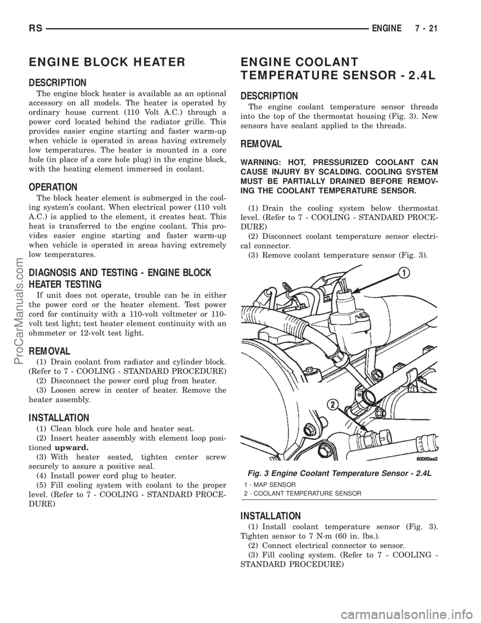
into the top of the thermostat housing (Fig. 3). New
sensors have sealant applied to the threads.
REMOVAL
WARNING: HOT, PRESSURIZED COOLANT CAN
CAUSE INJURY BY SCALDING. COOLING SYSTEM
MUST BE PARTIALLY DRAINED BEFORE REMOV-
ING THE COOLANT TEMPERATURE SENSOR.
(1) Drain the cooling system below thermostat
level. (Refer to 7 - COOLING - STANDARD PROCE-
DURE)
(2) Disconnect coolant temperature sensor electri-
cal connector.
(3) Remove coolant temperature sensor (Fig. 3).
INSTALLATION
(1) Install coolant temperature sensor (Fig. 3).
Tighten sensor to 7 N´m (60 in. lbs.).
(2) Connect electrical connector to sensor.
(3) Fill cooling system. (Refer to 7 - COOLING -
STANDARD PROCEDURE)
Fig. 3 Engine Coolant Temperature Sensor - 2.4L
1 - MAP SENSOR
2 - COOLANT TEMPERATURE SENSOR
RSENGINE7-21
ProCarManuals.com