engine mount CHRYSLER CARAVAN 2002 Service Manual
[x] Cancel search | Manufacturer: CHRYSLER, Model Year: 2002, Model line: CARAVAN, Model: CHRYSLER CARAVAN 2002Pages: 2399, PDF Size: 57.96 MB
Page 2365 of 2399
FUEL INJECTOR MECHANICAL MALFUNCTIONS
The PCM cannot determine if a fuel injector is
clogged, the needle is sticking or if the wrong injector
is installed. However, these could result in a rich or
lean condition causing the PCM to store a diagnostic
trouble code for either misfire, an oxygen sensor, or
the fuel system.
EXCESSIVE OIL CONSUMPTION
Although the PCM monitors engine exhaust oxygen
content when the system is in closed loop, it cannot
determine excessive oil consumption.
THROTTLE BODY AIR FLOW
The PCM cannot detect a clogged or restricted air
cleaner inlet or filter element.
VACUUM ASSIST
The PCM cannot detect leaks or restrictions in the
vacuum circuits of vacuum assisted engine control
system devices. However, these could cause the PCM
to store a MAP sensor diagnostic trouble code and
cause a high idle condition.
PCM SYSTEM GROUND
The PCM cannot determine a poor system ground.
However, one or more diagnostic trouble codes may
be generated as a result of this condition. The mod-
ule should be mounted to the body at all times, also
during diagnostic.
PCM CONNECTOR ENGAGEMENT
The PCM may not be able to determine spread or
damaged connector pins. However, it might store
diagnostic trouble codes as a result of spread connec-
tor pins.
DESCRIPTION - MONITORED SYSTEMS
There are new electronic circuit monitors that
check fuel, emission, engine and ignition perfor-
mance. These monitors use information from various
sensor circuits to indicate the overall operation of the
fuel, engine, ignition and emission systems and thus
the emissions performance of the vehicle.
The fuel, engine, ignition and emission systems
monitors do not indicate a specific component prob-
lem. They do indicate that there is an implied prob-
lem within one of the systems and that a specific
problem must be diagnosed.
If any of these monitors detect a problem affecting
vehicle emissions, the Malfunction Indicator (Check
Engine) Lamp will be illuminated. These monitors
generate Diagnostic Trouble Codes that can be dis-
played with the a DRBIIItscan tool.
The following is a list of the system monitors:
²EGR Monitor (if equipped)²Misfire Monitor
²Fuel System Monitor
²Oxygen Sensor Monitor
²Oxygen Sensor Heater Monitor
²Catalyst Monitor
²Evaporative System Leak Detection Monitor (if
equipped)
Following is a description of each system monitor,
and its DTC.
Refer to the appropriate Powertrain Diagnos-
tics Procedures manual for diagnostic proce-
dures.
OXYGEN SENSOR (O2S) MONITOR
Effective control of exhaust emissions is achieved
by an oxygen feedback system. The most important
element of the feedback system is the O2S. The O2S
is located in the exhaust path. Once it reaches oper-
ating temperatures of 300É to 350ÉC (572É to 662ÉF),
the sensor generates a voltage that is inversely pro-
portional to the amount of oxygen in the exhaust.
The information obtained by the sensor is used to
calculate the fuel injector pulse width. The PCM is
programmed to maintain the optimum air/fuel ratio.
At this mixture ratio, the catalyst works best to
remove hydrocarbons (HC), carbon monoxide (CO)
and nitrous oxide (NOx) from the exhaust.
The O2S is also the main sensing element for the
EGR (if equipped), Catalyst and Fuel Monitors.
The O2S may fail in any or all of the following
manners:
²Slow response rate
²Reduced output voltage
²Dynamic shift
²Shorted or open circuits
Response rate is the time required for the sensor to
switch from lean to rich once it is exposed to a richer
than optimum A/F mixture or vice versa. As the sen-
sor starts malfunctioning, it could take longer to
detect the changes in the oxygen content of the
exhaust gas.
The output voltage of the O2S ranges from 0 to 1
volt. A good sensor can easily generate any output
voltage in this range as it is exposed to different con-
centrations of oxygen. To detect a shift in the A/F
mixture (lean or rich), the output voltage has to
change beyond a threshold value. A malfunctioning
sensor could have difficulty changing beyond the
threshold value.
OXYGEN SENSOR HEATER MONITOR
If there is an oxygen sensor (O2S) DTC as well as
a O2S heater DTC, the O2S fault MUST be repaired
first. After the O2S fault is repaired, verify that the
heater circuit is operating correctly.
25 - 6 EMISSIONS CONTROLRS
EMISSIONS CONTROL (Continued)
ProCarManuals.com
Page 2366 of 2399

Effective control of exhaust emissions is achieved
by an oxygen feedback system. The most important
element of the feedback system is the O2S. The O2S
is located in the exhaust path. Once it reaches oper-
ating temperatures of 300É to 350ÉC (572 É to 662ÉF),
the sensor generates a voltage that is inversely pro-
portional to the amount of oxygen in the exhaust.
The information obtained by the sensor is used to
calculate the fuel injector pulse width. This main-
tains a 14.7 to 1 Air Fuel (A/F) ratio. At this mixture
ratio, the catalyst works best to remove hydrocarbons
(HC), carbon monoxide (CO) and nitrogen oxide
(NOx) from the exhaust.
The voltage readings taken from the O2S are very
temperature sensitive. The readings are not accurate
below 300ÉC. Heating of the O2S is done to allow the
engine controller to shift to closed loop control as
soon as possible. The heating element used to heat
the O2S must be tested to ensure that it is heating
the sensor properly.
The O2S circuit is monitored for a drop in voltage.
The sensor output is used to test the heater by iso-
lating the effect of the heater element on the O2S
output voltage from the other effects.
EGR MONITOR (if equipped)
The Powertrain Control Module (PCM) performs
an on-board diagnostic check of the EGR system.
The EGR monitor is used to test whether the EGR
system is operating within specifications. The diag-
nostic check activates only during selected engine/
driving conditions. When the conditions are met, the
EGR is turned off (solenoid energized) and the O2S
compensation control is monitored. Turning off the
EGR shifts the air fuel (A/F) ratio in the lean direc-
tion. The O2S data should indicate an increase in the
O2 concentration in the combustion chamber when
the exhaust gases are no longer recirculated. While
this test does not directly measure the operation of
the EGR system, it can be inferred from the shift in
the O2S data whether the EGR system is operating
correctly. Because the O2S is being used, the O2S
test must pass its test before the EGR test. Also
looks at EGR linear potentiometer for feedback.
MISFIRE MONITOR
Excessive engine misfire results in increased cata-
lyst temperature and causes an increase in HC emis-
sions. Severe misfires could cause catalyst damage.
To prevent catalytic convertor damage, the PCM
monitors engine misfire.
The Powertrain Control Module (PCM) monitors
for misfire during most engine operating conditions
(positive torque) by looking at changes in the crank-
shaft speed. If a misfire occurs the speed of the
crankshaft will vary more than normal.FUEL SYSTEM MONITOR
To comply with clean air regulations, vehicles are
equipped with catalytic converters. These converters
reduce the emission of hydrocarbons, oxides of nitro-
gen and carbon monoxide. The catalyst works best
when the air fuel (A/F) ratio is at or near the opti-
mum of 14.7 to 1.
The PCM is programmed to maintain the optimum
air/fuel ratio. This is done by making short term cor-
rections in the fuel injector pulse width based on the
O2S output. The programmed memory acts as a self
calibration tool that the engine controller uses to
compensate for variations in engine specifications,
sensor tolerances and engine fatigue over the life
span of the engine. By monitoring the actual air-fuel
ratio with the O2S (short term) and multiplying that
with the program long-term (adaptive) memory and
comparing that to the limit, it can be determined
whether it will pass an emissions test. If a malfunc-
tion occurs such that the PCM cannot maintain the
optimum A/F ratio, then the MIL will be illuminated.
CATALYST MONITOR
To comply with clean air regulations, vehicles are
equipped with catalytic converters. These converters
reduce the emission of hydrocarbons, oxides of nitro-
gen and carbon monoxide.
Normal vehicle miles or engine misfire can cause a
catalyst to decay. A meltdown of the ceramic core can
cause a reduction of the exhaust passage. This can
increase vehicle emissions and deteriorate engine
performance, driveability and fuel economy.
The catalyst monitor uses dual oxygen sensors
(O2S's) to monitor the efficiency of the converter. The
dual O2S's strategy is based on the fact that as a cat-
alyst deteriorates, its oxygen storage capacity and its
efficiency are both reduced. By monitoring the oxy-
gen storage capacity of a catalyst, its efficiency can
be indirectly calculated. The upstream O2S is used to
detect the amount of oxygen in the exhaust gas
before the gas enters the catalytic converter. The
PCM calculates the A/F mixture from the output of
the O2S. A low voltage indicates high oxygen content
(lean mixture). A high voltage indicates a low content
of oxygen (rich mixture).
When the upstream O2S detects a lean condition,
there is an abundance of oxygen in the exhaust gas.
A functioning converter would store this oxygen so it
can use it for the oxidation of HC and CO. As the
converter absorbs the oxygen, there will be a lack of
oxygen downstream of the converter. The output of
the downstream O2S will indicate limited activity in
this condition.
As the converter loses the ability to store oxygen,
the condition can be detected from the behavior of
the downstream O2S. When the efficiency drops, no
RSEMISSIONS CONTROL25-7
EMISSIONS CONTROL (Continued)
ProCarManuals.com
Page 2368 of 2399
nation by this diagnostic. When the vacuum in the
system exceeds about 19H2O (0.25 KPA), a vacuum
switch closes. The switch closure sends a signal to
the NGC. The NGC, via appropriate logic strategies
(described below), utilizes the switch signal, or lack
thereof, to make a determination of whether a leak is
present.
The NVLD device is designed with a normally open
vacuum switch, a normally closed solenoid, and a
seal, which is actuated by both the solenoid and a
diaphragm. The NVLD is located on the atmospheric
vent side of the canister. The NVLD assembly may
be mounted on top of the canister outlet, or in-line
between the canister and atmospheric vent filter. The
normally open vacuum switch will close with about 19
H2O (0.25 KPA) vacuum in the evaporative system.
The diaphragm actuates the switch. This is above the
opening point of the fuel inlet check valve in the fill
tube so cap off leaks can be detected. Submerged fill
systems must have recirculation lines that do not
have the in-line normally closed check valve that pro-
tects the system from failed nozzle liquid ingestion,
in order to detect cap off conditions.
The normally closed valve in the NVLD is intended
to maintain the seal on the evaporative system dur-
ing the engine off condition. If vacuum in the evapo-
rative system exceeds 39to 69H2O (0.75 to 1.5 KPA),
the valve will be pulled off the seat, opening the seal.
This will protect the system from excessive vacuum
as well as allowing sufficient purge flow in the event
that the solenoid was to become inoperative.
The solenoid actuates the valve to unseal the can-
ister vent while the engine is running. It also will be
used to close the vent during the medium and large
leak tests and during the purge flow check. This sole-
noid requires initial 1.5 amps of current to pull the
valve open but after 100 ms. will be duty cycled down
to an average of about 150 mA for the remainder of
the drive cycle.
Another feature in the device is a diaphragm that
will open the seal in the NVLD with pressure in the
evaporative system. The device will9blow off9at
about 0.59H2O (0.12 KPA) pressure to permit the
venting of vapors during refueling. An added benefit
to this is that it will also allow the tank to9breathe9
during increasing temperatures, thus limiting the
pressure in the tank to this low level. This is benefi-
cial because the induced vacuum during a subse-
quent declining temperature will achieve the switch
closed (pass threshold) sooner than if the tank had to
decay from a built up pressure.
The device itself has 3 wires: Switch sense, sole-
noid driver and ground. It also includes a resistor to
protect the switch from a short to battery or a short
to ground. The NGC utilizes a high-side driver to
energize and duty-cycle the solenoid.DESCRIPTION - HIGH AND LOW LIMITS
The PCM compares input signal voltages from each
input device with established high and low limits for
the device. If the input voltage is not within limits
and other criteria are met, the PCM stores a diagnos-
tic trouble code in memory. Other diagnostic trouble
code criteria might include engine RPM limits or
input voltages from other sensors or switches that
must be present before verifying a diagnostic trouble
code condition.
OPERATION
OPERATION - SYSTEM
The Powertrain Control Module (PCM) monitors
many different circuits in the fuel injection, ignition,
emission and engine systems. If the PCM senses a
problem with a monitored circuit often enough to
indicate an actual problem, it stores a Diagnostic
Trouble Code (DTC) in the PCM's memory. If the
code applies to a non-emissions related component or
system, and the problem is repaired or ceases to
exist, the PCM cancels the code after 40 warmup
cycles. Diagnostic trouble codes that affect vehicle
emissions illuminate the Malfunction Indicator Lamp
(MIL). Refer to Malfunction Indicator Lamp in this
section.
Certain criteria must be met before the PCM
stores a DTC in memory. The criteria may be a spe-
cific range of engine RPM, engine temperature,
and/or input voltage to the PCM.
The PCM might not store a DTC for a monitored
circuit even though a malfunction has occurred. This
may happen because one of the DTC criteria for the
circuit has not been met.For example, assume the
diagnostic trouble code criteria requires the PCM to
monitor the circuit only when the engine operates
between 750 and 2000 RPM. Suppose the sensor's
output circuit shorts to ground when engine operates
above 2400 RPM (resulting in 0 volt input to the
PCM). Because the condition happens at an engine
speed above the maximum threshold (2000 rpm), the
PCM will not store a DTC.
There are several operating conditions for which
the PCM monitors and sets DTC's. Refer to Moni-
tored Systems, Components, and Non-Monitored Cir-
cuits in this section.
NOTE: Various diagnostic procedures may actually
cause a diagnostic monitor to set a DTC. For
instance, pulling a spark plug wire to perform a
spark test may set the misfire code. When a repair
is completed and verified, use the DRBIIITscan tool
to erase all DTC's and extinguish the MIL.
RSEMISSIONS CONTROL25-9
EMISSIONS CONTROL (Continued)
ProCarManuals.com
Page 2376 of 2399
PCV VALVE
DESCRIPTION
The PCV valve contains a spring loaded plunger.
The plunger meters the amount of crankcase vapors
routed into the combustion chamber based on intake
manifold vacuum (Fig. 7) or (Fig. 8).
OPERATION
When the engine is not operating or during an
engine backfire, the spring forces the plunger back
against the seat. This prevents vapors from flowing
through the valve (Fig. 9).
When the engine is at idle or cruising, high mani-
fold vacuum is present. At these times manifold vac-
uum is able to completely compress the spring and
pull the plunger to the top of the valve (Fig. 10). In
this position there is minimal vapor flow through the
valve.
During periods of moderate intake manifold vac-
uum the plunger is only pulled part way back from
the inlet. This results in maximum vapor flow
through the valve (Fig. 11).
DIAGNOSIS AND TESTING - PCV SYSTEM
WARNING: APPLY PARKING BRAKE AND/OR
BLOCK WHEELS BEFORE PERFORMING ANY TEST
OR ADJUSTMENT WITH THE ENGINE OPERATING.
(1) With engine idling, remove the hose from the
PCV valve. If the valve is not plugged, a hissing
Fig. 7 PCV VALVE 2.4L
1 - PCV Valve
Fig. 8 PCV VALVE 3.3/3.8L
Fig. 9 Engine Off or Engine Backfire No Vapor Flow
Fig. 10 High Intake Manifold Vacuum Minimal Vapor
Flow
Fig. 11 Moderate Intake Manifold Vacuum Maximum
Vapor Flow
RSEVAPORATIVE EMISSIONS25-17
ProCarManuals.com
Page 2380 of 2399
(2) Disconnect the fresh air makeup hose on rear
valve cover.
(3) Remove the air box bolt.
(4) Remove the hose clamp at throttle body.
(5) Unlatch 2 clamps for air box cover.
(6) Remove air box cover.
(7) Disconnect the washer fluid fill hose.
(8) Remove air box.
(9) Remove the 2 bolts at the EGR valve.
(10) Remove the 2 bolts at the intake manifold.
(11) Remove front EGR tube.
REMOVAL - REAR TUBE - 3.5L
(1) Remove the battery, refer to the Battery sec-
tion.
(2) Remove the Battery tray/vacuum reservoir.
(3) Remove the speed control servo and bracket
and relocate.
(4) Remove the 2 bolts from the EGR valve.
(5) Remove the 2 bolts from the rear cylinder
head.
(6) Remove the EGR rear tube.
INSTALLATION
INSTALLATION - 2.4L
(1) Loose install EGR tube and gasket with attach-
ing bolts at intake manifold.
(2) Loose install EGR tube and gasket with attach-
ing bolts at EGR valve.
(3) Tighten bolts to EGR valve to 11.9 N´m (105
20 ins. lbs.).
(4) Tighten bolts to Intake manifold to 11.9 N´m
(105 20 ins. lbs.).
INSTALLATION - FRONT TUBE - 3.5L
(1) Install front EGR tube and gaskets.
(2) Install the 2 bolts at the EGR valve.
(3) Install the 2 bolts at the intake manifold.
(4) Tighten all 4 bolts.
(5) Install air box.
(6) Connect the washer fluid fill hose.
(7) Install air box cover.
(8) Latch 2 clamps for air box cover.
(9) Install the hose clamp at throttle body.
(10) Install the air box bolt.
(11) Connect the fresh air makeup hose on rear
valve cover.
(12) Connect the negative battery cable.
INSTALLATION - REAR TUBE - 3.5L
(1) Install the EGR rear tube.
(2) Install the 2 bolts to the rear cylinder head.
(3) Install the 2 bolts to the EGR valve.
(4) Tighten the 4 bolts.(5) Install the speed control servo and bracket,
refer to the speed control section.
(6) Install the Battery tray/vacuum reservoir refer
to the battery section.
(7) Install the battery, refer to the Battery section.
VA LV E
DESCRIPTION
The EGR system consists of:
²EGR tube (connects a passage in the intake
manifold to the exhaust port in the cylinder head)
²EGR valve
²Electronic EGR Transducer
²Connecting hoses
OPERATION
Refer to Monitored Systems - EGR Monitor in this
group for more information.
The engines use Exhaust Gas Recirculation (EGR)
systems. The EGR system reduces oxides of nitrogen
(NOx) in engine exhaust and helps prevent detona-
tion (engine knock). Under normal operating condi-
tions, engine cylinder temperature can reach more
than 3000ÉF. Formation of NOx increases proportion-
ally with combustion temperature. To reduce the
emission of these oxides, the cylinder temperature
must be lowered. The system allows a predetermined
amount of hot exhaust gas to recirculate and dilute
Fig. 1 EGR VALVE AND TUBE 2.4L
1 - EGR Tube
2 - EGR Valve
RSEXHAUST GAS RECIRCULATION25-21
TUBE (Continued)
ProCarManuals.com
Page 2381 of 2399
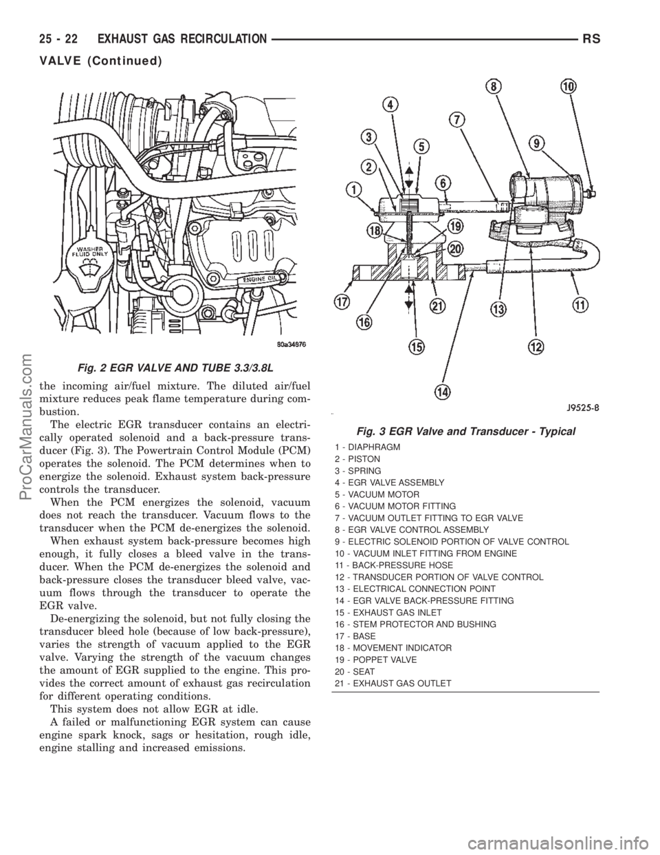
the incoming air/fuel mixture. The diluted air/fuel
mixture reduces peak flame temperature during com-
bustion.
The electric EGR transducer contains an electri-
cally operated solenoid and a back-pressure trans-
ducer (Fig. 3). The Powertrain Control Module (PCM)
operates the solenoid. The PCM determines when to
energize the solenoid. Exhaust system back-pressure
controls the transducer.
When the PCM energizes the solenoid, vacuum
does not reach the transducer. Vacuum flows to the
transducer when the PCM de-energizes the solenoid.
When exhaust system back-pressure becomes high
enough, it fully closes a bleed valve in the trans-
ducer. When the PCM de-energizes the solenoid and
back-pressure closes the transducer bleed valve, vac-
uum flows through the transducer to operate the
EGR valve.
De-energizing the solenoid, but not fully closing the
transducer bleed hole (because of low back-pressure),
varies the strength of vacuum applied to the EGR
valve. Varying the strength of the vacuum changes
the amount of EGR supplied to the engine. This pro-
vides the correct amount of exhaust gas recirculation
for different operating conditions.
This system does not allow EGR at idle.
A failed or malfunctioning EGR system can cause
engine spark knock, sags or hesitation, rough idle,
engine stalling and increased emissions.
Fig. 2 EGR VALVE AND TUBE 3.3/3.8L
Fig. 3 EGR Valve and Transducer - Typical
1 - DIAPHRAGM
2 - PISTON
3 - SPRING
4 - EGR VALVE ASSEMBLY
5 - VACUUM MOTOR
6 - VACUUM MOTOR FITTING
7 - VACUUM OUTLET FITTING TO EGR VALVE
8 - EGR VALVE CONTROL ASSEMBLY
9 - ELECTRIC SOLENOID PORTION OF VALVE CONTROL
10 - VACUUM INLET FITTING FROM ENGINE
11 - BACK-PRESSURE HOSE
12 - TRANSDUCER PORTION OF VALVE CONTROL
13 - ELECTRICAL CONNECTION POINT
14 - EGR VALVE BACK-PRESSURE FITTING
15 - EXHAUST GAS INLET
16 - STEM PROTECTOR AND BUSHING
17 - BASE
18 - MOVEMENT INDICATOR
19 - POPPET VALVE
20 - SEAT
21 - EXHAUST GAS OUTLET
25 - 22 EXHAUST GAS RECIRCULATIONRS
VALVE (Continued)
ProCarManuals.com
Page 2385 of 2399

Alternate Good Trips are used in place of Global
Good Trips for Comprehensive Components and
Major Monitors. If the Task Manager cannot run a
Global Good Trip because a component fault is stop-
ping the monitor from running, it will attempt to
count an Alternate Good Trip.
The Task Manager counts an Alternate Good Trip
for Comprehensive components when the following
conditions are met:
²Two minutes of engine run time, idle or driving
²No other faults occur
The Task Manager counts an Alternate Good Trip
for a Major Monitor when the monitor runs and
passes. Only the Major Monitor that failed needs to
pass to count an Alternate Good Trip.
Warm-Up Cycles
Once the MIL has been extinguished by the Good
Trip Counter, the PCM automatically switches to a
Warm-Up Cycle Counter that can be viewed on the
DRBIIIt. Warm-Up Cycles are used to erase DTCs
and Freeze Frames. Forty Warm-Up cycles must
occur in order for the PCM to self-erase a DTC and
Freeze Frame. A Warm-Up Cycle is defined as fol-
lows:
²Engine coolant temperature must start below
and rise above 160É F
²Engine coolant temperature must rise by 40É F
²No further faults occur
Freeze Frame Data Storage
Once a failure occurs, the Task Manager records
several engine operating conditions and stores it in a
Freeze Frame. The Freeze Frame is considered one
frame of information taken by an on-board data
recorder. When a fault occurs, the PCM stores the
input data from various sensors so that technicians
can determine under what vehicle operating condi-
tions the failure occurred.
The data stored in Freeze Frame is usually
recorded when a system fails the first time for two
trip faults. Freeze Frame data will only be overwrit-
ten by a different fault with a higher priority.
CAUTION: Erasing DTCs, either with the DRBIIIT;or
by disconnecting the battery, also clears all Freeze
Frame data.
Similar Conditions Window
The Similar Conditions Window displays informa-
tion about engine operation during a monitor. Abso-
lute MAP (engine load) and Engine RPM are stored
in this window when a failure occurs. There are two
different Similar conditions Windows: Fuel System
and Misfire.
FUEL SYSTEM²Fuel System Similar Conditions WindowÐ
An indicator that 'Absolute MAP When Fuel Sys Fail'
and 'RPM When Fuel Sys Failed' are all in the same
range when the failure occurred. Indicated by switch-
ing from 'NO' to 'YES'.
²Absolute MAP When Fuel Sys FailÐ The
stored MAP reading at the time of failure. Informs
the user at what engine load the failure occurred.
²Absolute MAPÐ A live reading of engine load
to aid the user in accessing the Similar Conditions
Window.
²RPM When Fuel Sys FailÐ The stored RPM
reading at the time of failure. Informs the user at
what engine RPM the failure occurred.
²Engine RPMÐ A live reading of engine RPM
to aid the user in accessing the Similar Conditions
Window.
²Adaptive Memory FactorÐ The PCM utilizes
both Short Term Compensation and Long Term Adap-
tive to calculate the Adaptive Memory Factor for
total fuel correction.
²Upstream O2S VoltsÐ A live reading of the
Oxygen Sensor to indicate its performance. For
example, stuck lean, stuck rich, etc.
²SCW Time in Window (Similar Conditions
Window Time in Window)Ð A timer used by the
PCM that indicates that, after all Similar Conditions
have been met, if there has been enough good engine
running time in the SCW without failure detected.
This timer is used to increment a Good Trip.
²Fuel System Good Trip CounterÐATrip
Counter used to turn OFF the MIL for Fuel System
DTCs. To increment a Fuel System Good Trip, the
engine must be in the Similar Conditions Window,
Adaptive Memory Factor must be less than cali-
brated threshold and the Adaptive Memory Factor
must stay below that threshold for a calibrated
amount of time.
²Test Done This TripÐ Indicates that the
monitor has already been run and completed during
the current trip.
MISFIRE
²Same Misfire Warm-Up StateÐ Indicates if
the misfire occurred when the engine was warmed up
(above 160É F).
²In Similar Misfire WindowÐ An indicator
that 'Absolute MAP When Misfire Occurred' and
'RPM When Misfire Occurred' are all in the same
range when the failure occurred. Indicated by switch-
ing from 'NO' to 'YES'.
²Absolute MAP When Misfire OccurredÐ
The stored MAP reading at the time of failure.
Informs the user at what engine load the failure
occurred.
25 - 26 ON-BOARD DIAGNOSTICSRS
TASK MANAGER (Continued)
ProCarManuals.com
Page 2390 of 2399

EXHAUST GAS RECIRCULATION
TABLE OF CONTENTS
page page
EXHAUST GAS RECIRCULATION
DESCRIPTION..........................3
OPERATION............................3
VA LV E
DESCRIPTION..........................3
OPERATION............................3REMOVAL.............................4
INSTALLATION..........................4
VALVE COOLER
DESCRIPTION..........................4
REMOVAL.............................4
INSTALLATION..........................5
EXHAUST GAS
RECIRCULATION
DESCRIPTION
The EGR system reduces oxides of nitrogen (NOx)
in the engine exhaust. This is accomplished by allow-
ing a predetermined amount of hot exhaust gas to
recirculate and dilute the incoming fuel/air mixture.
A malfunctioning EGR system can cause engine
stumble, sags, or hesitation, rough idle, engine stall-
ing and poor driveability.
OPERATION
The system consists of:
²An EGR valve assembly. The valve is located on
the rear of the engine above the exhaust manfiold.
²An EGR solenoid.The EGR solenoid controls the
ªon timeº of the EGR valve.
²The ECM operates the EGR solenoid. The ECM
is located inside the vehicle under the instrument
panel.
²An EGR tube connects a passage in the EGR
valve to the rear of the exhaust manifold.
²The vacuum pump supplies vacuum for the EGR
solenoid and the EGR valve. This pump also supplies
vacuum for operation of the power brake boosterb
and the heating and air conditioning system. The
pump is located internally in the front of the engine
block and is driven by the crankshaft gear.²Vacuum lines and hoses connect the various
components.
When the ECM supplies a variable ground signal
to the EGR solenoid, EGR system operation starts to
occur. The ECM will monitor and determine when to
supply and remove this variable ground signal. This
will depend on inputs from the engine coolant tem-
perature, throttle position and engine speed sensors.
When the variable ground signal is supplied to the
EGR solenoid, vacuum from the vacuum pump will
be allowed to pass through the EGR solenoid and on
to the EGR valve with a connecting hose.
Exhaust gas recirculation will begin in this order
when:
²The ECM determines that EGR system opera-
tion is necessary.
²The engine is running to operate the vacuum
pump.
²A variable ground signal is supplied to the EGR
solenoid.
²Variable vacuum passes through the EGR sole-
noid to the EGR valve.
²The inlet seat (poppet valve) at the bottom of
the EGR valve opens to dilute and recirculate
exhaust gas back into the intake manifold.
The EGR system will be shut down by the ECM
after 60 seconds of continuous engine idling to
improve idle quality.
RGEXHAUST GAS RECIRCULATION25a-3
ProCarManuals.com
Page 2391 of 2399

VA LV E
DESCRIPTION
The EGR system consists of (Fig. 1):
²EGR valve
²EGR tube
²Vacuum hoses
²EGR cooler
²EGR solenoid
OPERATION
The engines use Exhaust Gas Recirculation (EGR)
systems. The EGR system reduces oxides of nitrogen
(NOx) in engine exhaust and helps prevent detona-
tion (engine knock). Under normal operating condi-
tions, engine cylinder temperature can reach more
than 3000ÉF. Formation of NOx increases proportion-
ally with combustion temperature. To reduce the
emission of these oxides, the cylinder temperature
must be lowered. The system allows a predetermined
amount of hot exhaust gas to recirculate and dilute
the incoming air/fuel mixture. The diluted air/fuel
mixture reduces peak flame temperature during com-
bustion.
REMOVAL
(1) Remove engine cover (Refer to 9 - ENGINE -
REMOVAL).
(2) Remove front wiper unit (Refer to 8 - ELEC-
TRICAL/WIPERS/WASHERS/WIPER MODULE -
REMOVAL).
(3) Disconnect EGR valve vacuum line.
(4) Remove EGR cooler to EGR valve retaining
bolts (Fig. 1).
(5) Remove EGR valve retaining nuts (Fig. 1) and
EGR valve.
INSTALLATION
(1) Clean gasket mating surfaces.
(2) Install EGR valve (Fig. 1). Torque nuts to
32.4N´m.
(3) Connect EGR cooler to EGR valve (Fig. 1).
Torque bolts to 32.4N´m
(4) Install front wiper unit (Refer to 8 - ELECTRI-
CAL/WIPERS/WASHERS/WIPER MODULE -
INSTALLATION).
(5) Install engine cover (Refer to 9 - ENGINE -
INSTALLATION).
Fig. 1 EGR COMPONENTS
1 - HOSE CLAMP
2 - COOLANT HOSE
3 - HOSE CLAMP
4 - EGR VALVE RETAINING NUT
5 - E G R VA LV E
6 - COOLANT HOSE
7 - EGR VALVE GASKET
8 - EGR VALVE RETAINING STUDS
9 - EGR COOLER RETAINING BOLT
10 - HOSE CLAMP
11 - HOSE CLAMP
12 - EGR COOLER
13 - EGR COOLER TO EGR VALVE RETAINING BOLT
14 - TURBOCHARGER BRACKET
15 - TURBOCHARGER BRACKET RETAINING BOLT
16 - TURBOCHARGER DOWNPIPE
17 - TURBOCHARGER DOWNPIPE RETAINING NUT
18 - DOWNPIPE GASKET
19 - DOWNPIPE STUD
25a - 4 EXHAUST GAS RECIRCULATIONRG
ProCarManuals.com