ECU CHRYSLER CARAVAN 2002 Service Manual
[x] Cancel search | Manufacturer: CHRYSLER, Model Year: 2002, Model line: CARAVAN, Model: CHRYSLER CARAVAN 2002Pages: 2399, PDF Size: 57.96 MB
Page 1399 of 2399
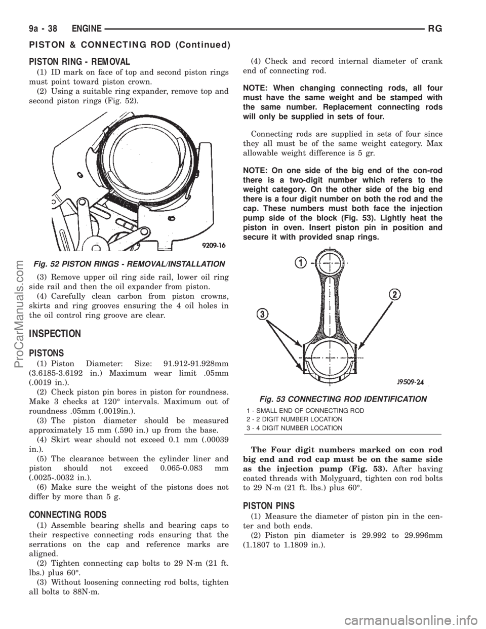
PISTON RING - REMOVAL
(1) ID mark on face of top and second piston rings
must point toward piston crown.
(2) Using a suitable ring expander, remove top and
second piston rings (Fig. 52).
(3) Remove upper oil ring side rail, lower oil ring
side rail and then the oil expander from piston.
(4) Carefully clean carbon from piston crowns,
skirts and ring grooves ensuring the 4 oil holes in
the oil control ring groove are clear.
INSPECTION
PISTONS
(1) Piston Diameter: Size: 91.912-91.928mm
(3.6185-3.6192 in.) Maximum wear limit .05mm
(.0019 in.).
(2) Check piston pin bores in piston for roundness.
Make 3 checks at 120É intervals. Maximum out of
roundness .05mm (.0019in.).
(3) The piston diameter should be measured
approximately 15 mm (.590 in.) up from the base.
(4) Skirt wear should not exceed 0.1 mm (.00039
in.).
(5) The clearance between the cylinder liner and
piston should not exceed 0.065-0.083 mm
(.0025-.0032 in.).
(6) Make sure the weight of the pistons does not
differ by more than 5 g.
CONNECTING RODS
(1) Assemble bearing shells and bearing caps to
their respective connecting rods ensuring that the
serrations on the cap and reference marks are
aligned.
(2) Tighten connecting cap bolts to 29 N´m (21 ft.
lbs.) plus 60É.
(3) Without loosening connecting rod bolts, tighten
all bolts to 88N´m.(4) Check and record internal diameter of crank
end of connecting rod.
NOTE: When changing connecting rods, all four
must have the same weight and be stamped with
the same number. Replacement connecting rods
will only be supplied in sets of four.
Connecting rods are supplied in sets of four since
they all must be of the same weight category. Max
allowable weight difference is 5 gr.
NOTE: On one side of the big end of the con-rod
there is a two-digit number which refers to the
weight category. On the other side of the big end
there is a four digit number on both the rod and the
cap. These numbers must both face the injection
pump side of the block (Fig. 53). Lightly heat the
piston in oven. Insert piston pin in position and
secure it with provided snap rings.
The Four digit numbers marked on con rod
big end and rod cap must be on the same side
as the injection pump (Fig. 53).After having
coated threads with Molyguard, tighten con rod bolts
to 29 N´m (21 ft. lbs.) plus 60É.
PISTON PINS
(1) Measure the diameter of piston pin in the cen-
ter and both ends.
(2) Piston pin diameter is 29.992 to 29.996mm
(1.1807 to 1.1809 in.).
Fig. 52 PISTON RINGS - REMOVAL/INSTALLATION
Fig. 53 CONNECTING ROD IDENTIFICATION
1 - SMALL END OF CONNECTING ROD
2 - 2 DIGIT NUMBER LOCATION
3 - 4 DIGIT NUMBER LOCATION
9a - 38 ENGINERG
PISTON & CONNECTING ROD (Continued)
ProCarManuals.com
Page 1400 of 2399
INSTALLATION
PISTON PIN INSTALLATION
(1) Secure connecting rod in soft jawed vice.
(2) Lubricate piston pin and piston with clean
engine oil.
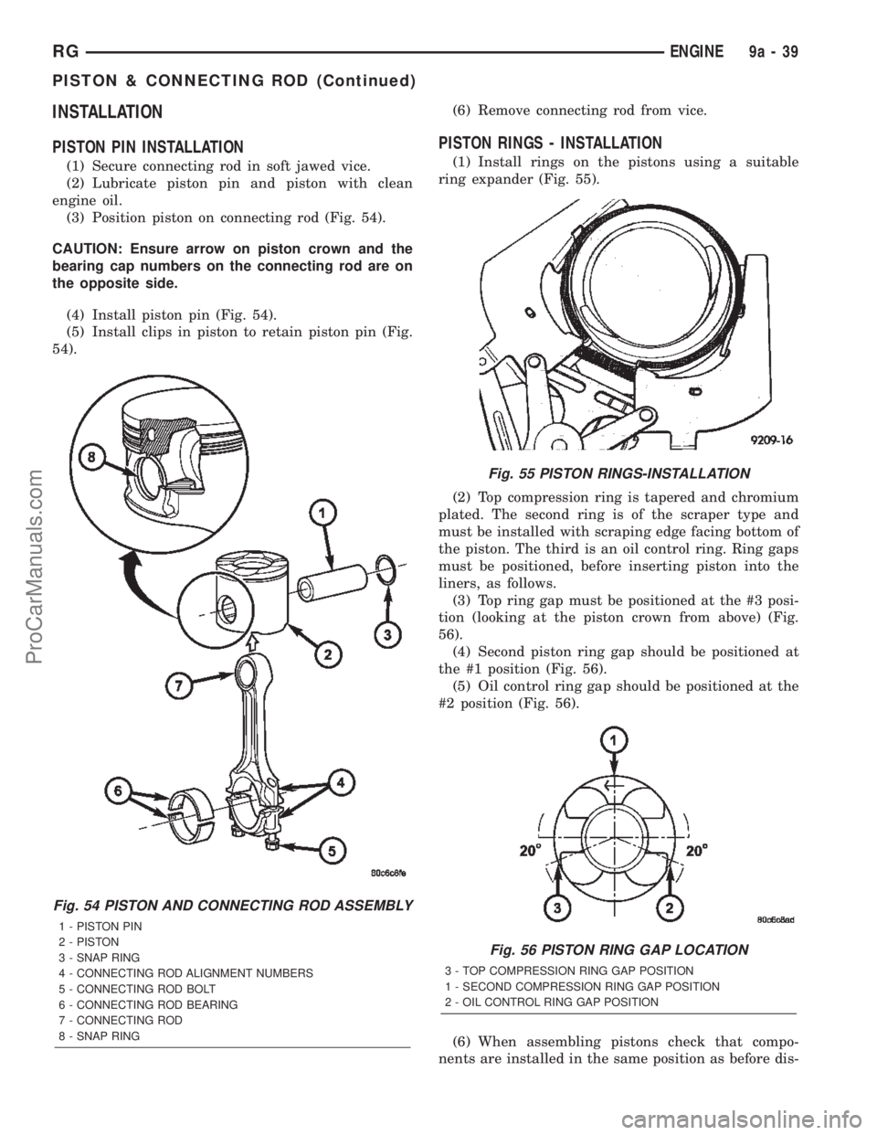
(3) Position piston on connecting rod (Fig. 54).
CAUTION: Ensure arrow on piston crown and the
bearing cap numbers on the connecting rod are on
the opposite side.
(4) Install piston pin (Fig. 54).
(5) Install clips in piston to retain piston pin (Fig.
54).(6) Remove connecting rod from vice.
PISTON RINGS - INSTALLATION
(1) Install rings on the pistons using a suitable
ring expander (Fig. 55).
(2) Top compression ring is tapered and chromium
plated. The second ring is of the scraper type and
must be installed with scraping edge facing bottom of
the piston. The third is an oil control ring. Ring gaps
must be positioned, before inserting piston into the
liners, as follows.
(3) Top ring gap must be positioned at the #3 posi-
tion (looking at the piston crown from above) (Fig.
56).
(4) Second piston ring gap should be positioned at
the #1 position (Fig. 56).
(5) Oil control ring gap should be positioned at the
#2 position (Fig. 56).
(6) When assembling pistons check that compo-
nents are installed in the same position as before dis-
Fig. 54 PISTON AND CONNECTING ROD ASSEMBLY
1 - PISTON PIN
2 - PISTON
3 - SNAP RING
4 - CONNECTING ROD ALIGNMENT NUMBERS
5 - CONNECTING ROD BOLT
6 - CONNECTING ROD BEARING
7 - CONNECTING ROD
8 - SNAP RING
Fig. 55 PISTON RINGS-INSTALLATION
Fig. 56 PISTON RING GAP LOCATION
3 - TOP COMPRESSION RING GAP POSITION
1 - SECOND COMPRESSION RING GAP POSITION
2 - OIL CONTROL RING GAP POSITION
RGENGINE9a-39
PISTON & CONNECTING ROD (Continued)
ProCarManuals.com
Page 1427 of 2399
SPECIAL TOOLS
EXHAUST SYSTEM
CATALYTIC CONVERTER
DESCRIPTION
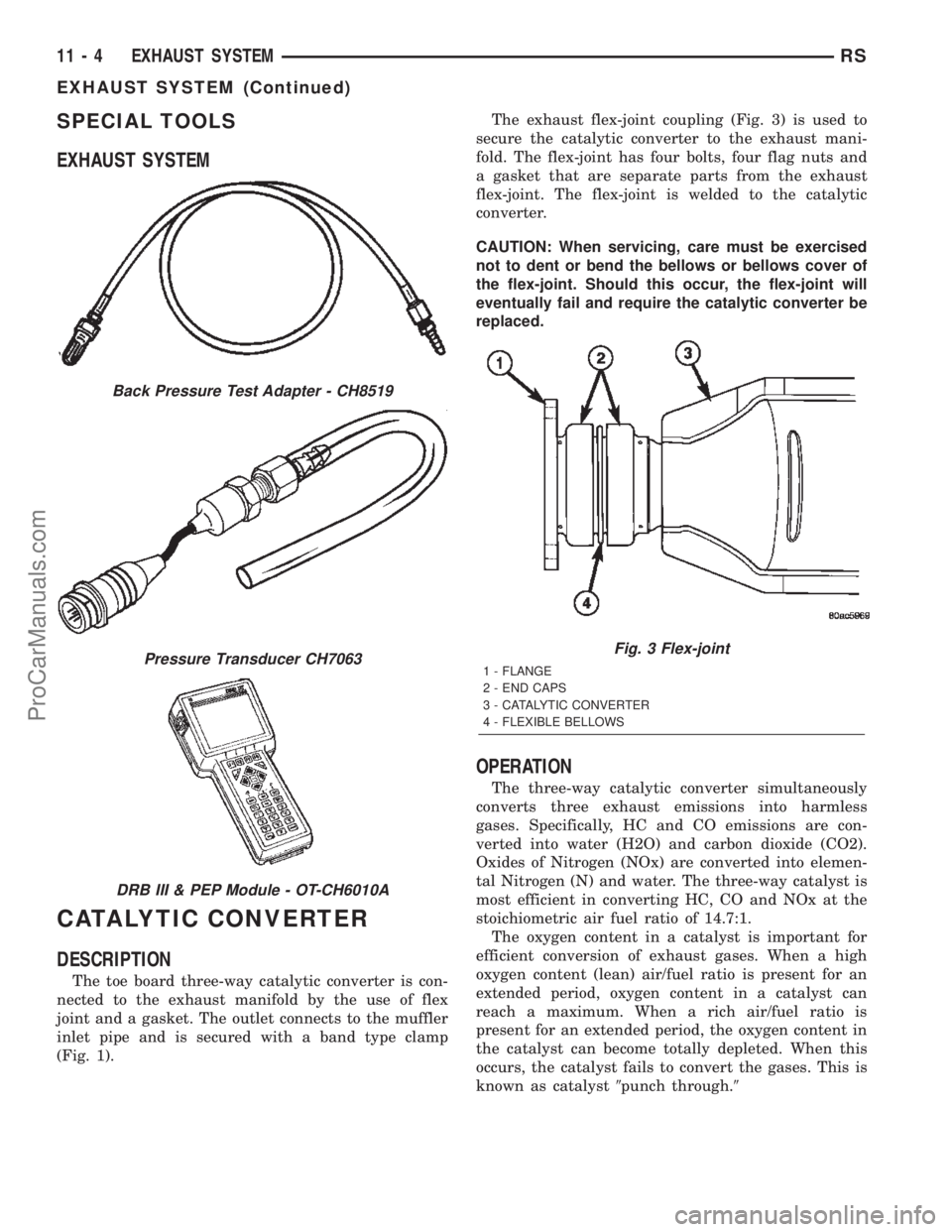
The toe board three-way catalytic converter is con-
nected to the exhaust manifold by the use of flex
joint and a gasket. The outlet connects to the muffler
inlet pipe and is secured with a band type clamp
(Fig. 1).The exhaust flex-joint coupling (Fig. 3) is used to
secure the catalytic converter to the exhaust mani-
fold. The flex-joint has four bolts, four flag nuts and
a gasket that are separate parts from the exhaust
flex-joint. The flex-joint is welded to the catalytic
converter.
CAUTION: When servicing, care must be exercised
not to dent or bend the bellows or bellows cover of
the flex-joint. Should this occur, the flex-joint will
eventually fail and require the catalytic converter be
replaced.
OPERATION
The three-way catalytic converter simultaneously
converts three exhaust emissions into harmless
gases. Specifically, HC and CO emissions are con-
verted into water (H2O) and carbon dioxide (CO2).
Oxides of Nitrogen (NOx) are converted into elemen-
tal Nitrogen (N) and water. The three-way catalyst is
most efficient in converting HC, CO and NOx at the
stoichiometric air fuel ratio of 14.7:1.
The oxygen content in a catalyst is important for
efficient conversion of exhaust gases. When a high
oxygen content (lean) air/fuel ratio is present for an
extended period, oxygen content in a catalyst can
reach a maximum. When a rich air/fuel ratio is
present for an extended period, the oxygen content in
the catalyst can become totally depleted. When this
occurs, the catalyst fails to convert the gases. This is
known as catalyst9punch through.9
Back Pressure Test Adapter - CH8519
Pressure Transducer CH7063
DRB III & PEP Module - OT-CH6010A
Fig. 3 Flex-joint
1 - FLANGE
2 - END CAPS
3 - CATALYTIC CONVERTER
4 - FLEXIBLE BELLOWS
11 - 4 EXHAUST SYSTEMRS
EXHAUST SYSTEM (Continued)
ProCarManuals.com
Page 1457 of 2399
INSTALLATION
(1) Insert level sensor wires into bottom of opening
in module.
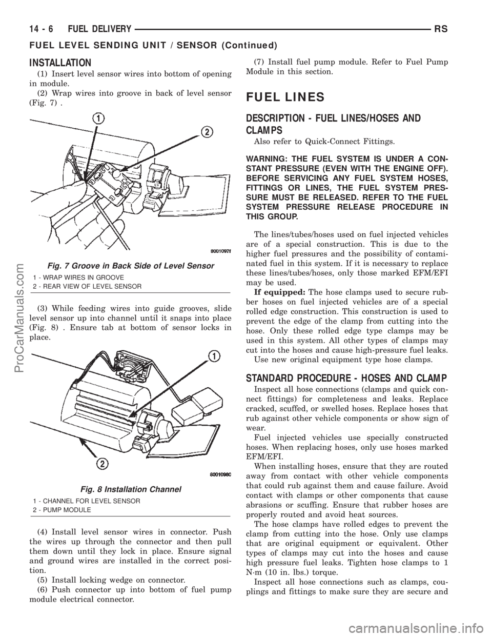
(2) Wrap wires into groove in back of level sensor
(Fig. 7) .
(3) While feeding wires into guide grooves, slide
level sensor up into channel until it snaps into place
(Fig. 8) . Ensure tab at bottom of sensor locks in
place.
(4) Install level sensor wires in connector. Push
the wires up through the connector and then pull
them down until they lock in place. Ensure signal
and ground wires are installed in the correct posi-
tion.
(5) Install locking wedge on connector.
(6) Push connector up into bottom of fuel pump
module electrical connector.(7) Install fuel pump module. Refer to Fuel Pump
Module in this section.
FUEL LINES
DESCRIPTION - FUEL LINES/HOSES AND
CLAMPS
Also refer to Quick-Connect Fittings.
WARNING: THE FUEL SYSTEM IS UNDER A CON-
STANT PRESSURE (EVEN WITH THE ENGINE OFF).
BEFORE SERVICING ANY FUEL SYSTEM HOSES,
FITTINGS OR LINES, THE FUEL SYSTEM PRES-
SURE MUST BE RELEASED. REFER TO THE FUEL
SYSTEM PRESSURE RELEASE PROCEDURE IN
THIS GROUP.
The lines/tubes/hoses used on fuel injected vehicles
are of a special construction. This is due to the
higher fuel pressures and the possibility of contami-
nated fuel in this system. If it is necessary to replace
these lines/tubes/hoses, only those marked EFM/EFI
may be used.
If equipped:The hose clamps used to secure rub-
ber hoses on fuel injected vehicles are of a special
rolled edge construction. This construction is used to
prevent the edge of the clamp from cutting into the
hose. Only these rolled edge type clamps may be
used in this system. All other types of clamps may
cut into the hoses and cause high-pressure fuel leaks.
Use new original equipment type hose clamps.
STANDARD PROCEDURE - HOSES AND CLAMP
Inspect all hose connections (clamps and quick con-
nect fittings) for completeness and leaks. Replace
cracked, scuffed, or swelled hoses. Replace hoses that
rub against other vehicle components or show sign of
wear.
Fuel injected vehicles use specially constructed
hoses. When replacing hoses, only use hoses marked
EFM/EFI.
When installing hoses, ensure that they are routed
away from contact with other vehicle components
that could rub against them and cause failure. Avoid
contact with clamps or other components that cause
abrasions or scuffing. Ensure that rubber hoses are
properly routed and avoid heat sources.
The hose clamps have rolled edges to prevent the
clamp from cutting into the hose. Only use clamps
that are original equipment or equivalent. Other
types of clamps may cut into the hoses and cause
high pressure fuel leaks. Tighten hose clamps to 1
N´m (10 in. lbs.) torque.
Inspect all hose connections such as clamps, cou-
plings and fittings to make sure they are secure and
Fig. 7 Groove in Back Side of Level Sensor
1 - WRAP WIRES IN GROOVE
2 - REAR VIEW OF LEVEL SENSOR
Fig. 8 Installation Channel
1 - CHANNEL FOR LEVEL SENSOR
2 - PUMP MODULE
14 - 6 FUEL DELIVERYRS
FUEL LEVEL SENDING UNIT / SENSOR (Continued)
ProCarManuals.com
Page 1464 of 2399
(4) Install the 3 screws at the filler door.
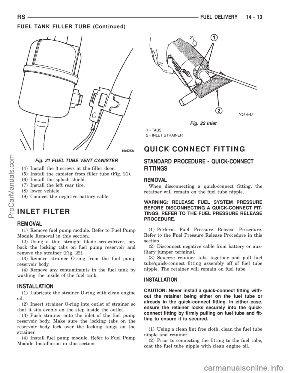
(5) Install the canister from filler tube (Fig. 21).
(6) Install the splash shield.
(7) Install the left rear tire.
(8) lower vehicle.
(9) Connect the negative battery cable.
INLET FILTER
REMOVAL
(1) Remove fuel pump module. Refer to Fuel Pump
Module Removal in this section.
(2) Using a thin straight blade screwdriver, pry
back the locking tabs on fuel pump reservoir and
remove the strainer (Fig. 22).
(3) Remove strainer O-ring from the fuel pump
reservoir body.
(4) Remove any contaminants in the fuel tank by
washing the inside of the fuel tank.
INSTALLATION
(1) Lubricate the strainer O-ring with clean engine
oil.
(2) Insert strainer O-ring into outlet of strainer so
that it sits evenly on the step inside the outlet.
(3) Push strainer onto the inlet of the fuel pump
reservoir body. Make sure the locking tabs on the
reservoir body lock over the locking tangs on the
strainer.
(4) Install fuel pump module. Refer to Fuel Pump
Module Installation in this section.
QUICK CONNECT FITTING
STANDARD PROCEDURE - QUICK-CONNECT
FITTINGS
REMOVAL
When disconnecting a quick-connect fitting, the
retainer will remain on the fuel tube nipple.
WARNING: RELEASE FUEL SYSTEM PRESSURE
BEFORE DISCONNECTING A QUICK-CONNECT FIT-
TINGS. REFER TO THE FUEL PRESSURE RELEASE
PROCEDURE.
(1) Perform Fuel Pressure Release Procedure.
Refer to the Fuel Pressure Release Procedure in this
section.
(2) Disconnect negative cable from battery or aux-
iliary jumper terminal.
(3) Squeeze retainer tabs together and pull fuel
tube/quick-connect fitting assembly off of fuel tube
nipple. The retainer will remain on fuel tube.
INSTALLATION
CAUTION: Never install a quick-connect fitting with-
out the retainer being either on the fuel tube or
already in the quick-connect fitting. In either case,
ensure the retainer locks securely into the quick-
connect fitting by firmly pulling on fuel tube and fit-
ting to ensure it is secured.
(1) Using a clean lint free cloth, clean the fuel tube
nipple and retainer.
(2) Prior to connecting the fitting to the fuel tube,
coat the fuel tube nipple with clean engine oil.
Fig. 21 FUEL TUBE VENT CANISTER
Fig. 22 Inlet
1 - TABS
2 - INLET STRAINER
RSFUEL DELIVERY14-13
FUEL TANK FILLER TUBE (Continued)
ProCarManuals.com
Page 1465 of 2399
(3) Push the quick-connect fitting over the fuel
tube until theretainer seats and a click is heard.
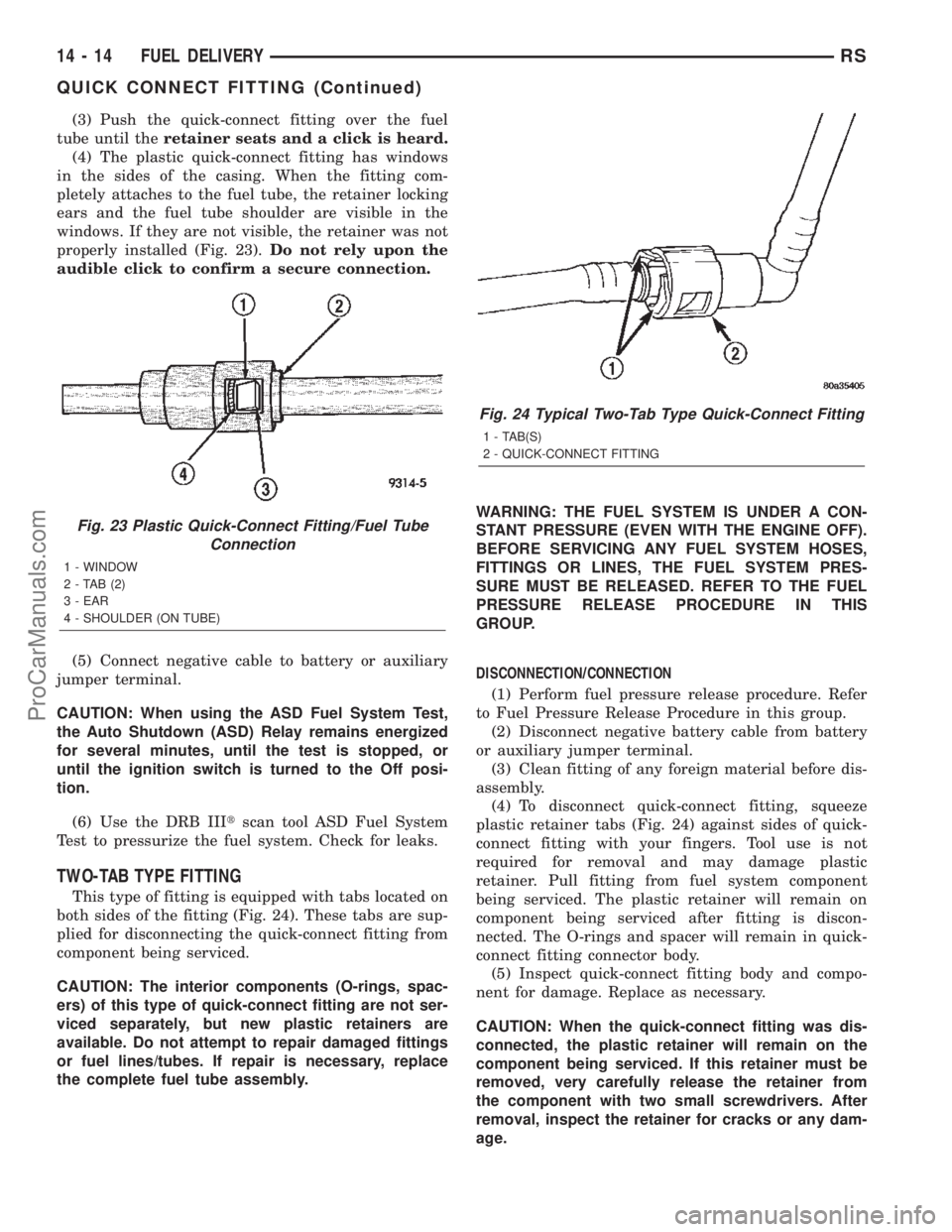
(4) The plastic quick-connect fitting has windows
in the sides of the casing. When the fitting com-
pletely attaches to the fuel tube, the retainer locking
ears and the fuel tube shoulder are visible in the
windows. If they are not visible, the retainer was not
properly installed (Fig. 23).Do not rely upon the
audible click to confirm a secure connection.
(5) Connect negative cable to battery or auxiliary
jumper terminal.
CAUTION: When using the ASD Fuel System Test,
the Auto Shutdown (ASD) Relay remains energized
for several minutes, until the test is stopped, or
until the ignition switch is turned to the Off posi-
tion.
(6) Use the DRB IIItscan tool ASD Fuel System
Test to pressurize the fuel system. Check for leaks.
TWO-TAB TYPE FITTING
This type of fitting is equipped with tabs located on
both sides of the fitting (Fig. 24). These tabs are sup-
plied for disconnecting the quick-connect fitting from
component being serviced.
CAUTION: The interior components (O-rings, spac-
ers) of this type of quick-connect fitting are not ser-
viced separately, but new plastic retainers are
available. Do not attempt to repair damaged fittings
or fuel lines/tubes. If repair is necessary, replace
the complete fuel tube assembly.WARNING: THE FUEL SYSTEM IS UNDER A CON-
STANT PRESSURE (EVEN WITH THE ENGINE OFF).
BEFORE SERVICING ANY FUEL SYSTEM HOSES,
FITTINGS OR LINES, THE FUEL SYSTEM PRES-
SURE MUST BE RELEASED. REFER TO THE FUEL
PRESSURE RELEASE PROCEDURE IN THIS
GROUP.
DISCONNECTION/CONNECTION
(1) Perform fuel pressure release procedure. Refer
to Fuel Pressure Release Procedure in this group.
(2) Disconnect negative battery cable from battery
or auxiliary jumper terminal.
(3) Clean fitting of any foreign material before dis-
assembly.
(4) To disconnect quick-connect fitting, squeeze
plastic retainer tabs (Fig. 24) against sides of quick-
connect fitting with your fingers. Tool use is not
required for removal and may damage plastic
retainer. Pull fitting from fuel system component
being serviced. The plastic retainer will remain on
component being serviced after fitting is discon-
nected. The O-rings and spacer will remain in quick-
connect fitting connector body.
(5) Inspect quick-connect fitting body and compo-
nent for damage. Replace as necessary.
CAUTION: When the quick-connect fitting was dis-
connected, the plastic retainer will remain on the
component being serviced. If this retainer must be
removed, very carefully release the retainer from
the component with two small screwdrivers. After
removal, inspect the retainer for cracks or any dam-
age.
Fig. 23 Plastic Quick-Connect Fitting/Fuel Tube
Connection
1 - WINDOW
2-TAB(2)
3 - EAR
4 - SHOULDER (ON TUBE)
Fig. 24 Typical Two-Tab Type Quick-Connect Fitting
1 - TAB(S)
2 - QUICK-CONNECT FITTING
14 - 14 FUEL DELIVERYRS
QUICK CONNECT FITTING (Continued)
ProCarManuals.com
Page 1495 of 2399
(6) Support engine and remove right engine mount
assembly.
(7) Remove outer timing belt cover (Refer to 9 -
ENGINE/VALVE TIMING/TIMING BELT / CHAIN
COVER(S) - REMOVAL).
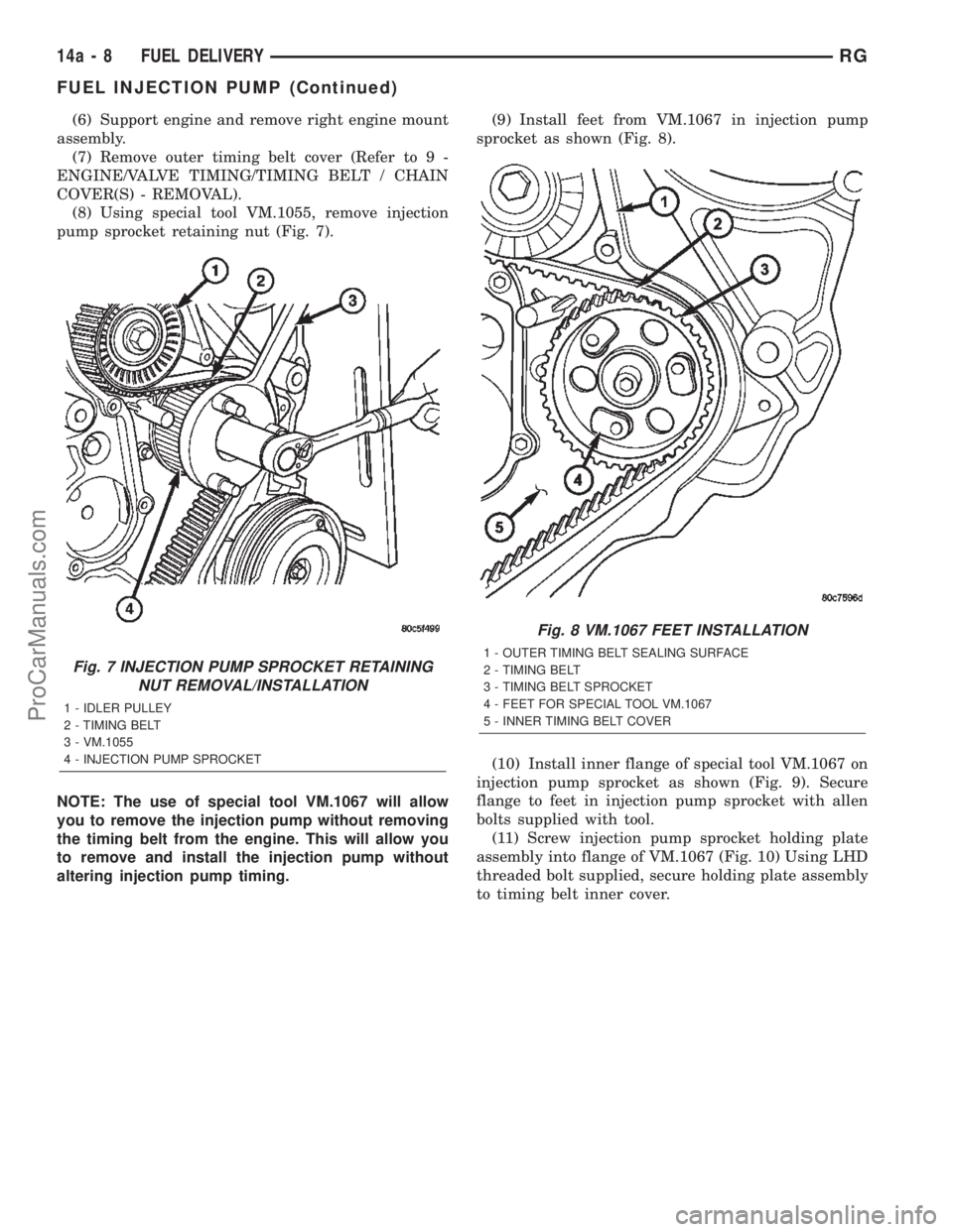
(8) Using special tool VM.1055, remove injection
pump sprocket retaining nut (Fig. 7).
NOTE: The use of special tool VM.1067 will allow
you to remove the injection pump without removing
the timing belt from the engine. This will allow you
to remove and install the injection pump without
altering injection pump timing.(9) Install feet from VM.1067 in injection pump
sprocket as shown (Fig. 8).
(10) Install inner flange of special tool VM.1067 on
injection pump sprocket as shown (Fig. 9). Secure
flange to feet in injection pump sprocket with allen
bolts supplied with tool.
(11) Screw injection pump sprocket holding plate
assembly into flange of VM.1067 (Fig. 10) Using LHD
threaded bolt supplied, secure holding plate assembly
to timing belt inner cover.
Fig. 7 INJECTION PUMP SPROCKET RETAINING
NUT REMOVAL/INSTALLATION
1 - IDLER PULLEY
2 - TIMING BELT
3 - VM.1055
4 - INJECTION PUMP SPROCKET
Fig. 8 VM.1067 FEET INSTALLATION
1 - OUTER TIMING BELT SEALING SURFACE
2 - TIMING BELT
3 - TIMING BELT SPROCKET
4 - FEET FOR SPECIAL TOOL VM.1067
5 - INNER TIMING BELT COVER
14a - 8 FUEL DELIVERYRG
FUEL INJECTION PUMP (Continued)
ProCarManuals.com
Page 1521 of 2399
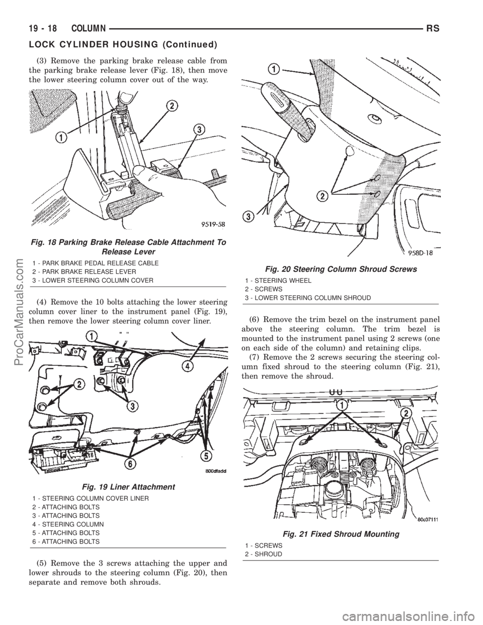
(3) Remove the parking brake release cable from
the parking brake release lever (Fig. 18), then move
the lower steering column cover out of the way.
(4)
Remove the 10 bolts attaching the lower steering
column cover liner to the instrument panel (Fig. 19),
then remove the lower steering column cover liner.
(5) Remove the 3 screws attaching the upper and
lower shrouds to the steering column (Fig. 20), then
separate and remove both shrouds.(6) Remove the trim bezel on the instrument panel
above the steering column. The trim bezel is
mounted to the instrument panel using 2 screws (one
on each side of the column) and retaining clips.
(7) Remove the 2 screws securing the steering col-
umn fixed shroud to the steering column (Fig. 21),
then remove the shroud.
Fig. 18 Parking Brake Release Cable Attachment To
Release Lever
1 - PARK BRAKE PEDAL RELEASE CABLE
2 - PARK BRAKE RELEASE LEVER
3 - LOWER STEERING COLUMN COVER
Fig. 19 Liner Attachment
1 - STEERING COLUMN COVER LINER
2 - ATTACHING BOLTS
3 - ATTACHING BOLTS
4 - STEERING COLUMN
5 - ATTACHING BOLTS
6 - ATTACHING BOLTS
Fig. 20 Steering Column Shroud Screws
1 - STEERING WHEEL
2 - SCREWS
3 - LOWER STEERING COLUMN SHROUD
Fig. 21 Fixed Shroud Mounting
1 - SCREWS
2 - SHROUD
19 - 18 COLUMNRS
LOCK CYLINDER HOUSING (Continued)
ProCarManuals.com
Page 1523 of 2399
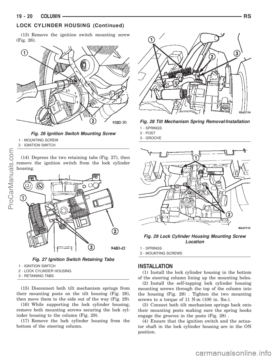
(13) Remove the ignition switch mounting screw
(Fig. 26).
(14) Depress the two retaining tabs (Fig. 27), then
remove the ignition switch from the lock cylinder
housing.
(15) Disconnect both tilt mechanism springs from
their mounting posts on the tilt housing (Fig. 28),
then move them to the side out of the way (Fig. 29).
(16) While supporting the lock cylinder housing,
remove both mounting screws securing the lock cyl-
inder housing to the column (Fig. 29).
(17) Remove the lock cylinder housing from the
bottom of the steering column.
INSTALLATION
(1) Install the lock cylinder housing in the bottom
of the steering column lining up the mounting holes.
(2) Install the self-tapping lock cylinder housing
mounting screws through the top of the column into
the housing (Fig. 29) . Tighten the two mounting
screws to a torque of 11 N´m (100 in. lbs.).
(3) Connect both tilt mechanism springs back onto
their mounting posts making sure the spring hooks
engage the grooves in the posts (Fig. 28) .
(4) Ensure that the ignition switch and the actua-
tor shaft in the lock cylinder housing are in the ON
position.
Fig. 26 Ignition Switch Mounting Screw
1 - MOUNTING SCREW
2 - IGNITION SWITCH
Fig. 27 Ignition Switch Retaining Tabs
1 - IGNITION SWITCH
2 - LOCK CYLINDER HOUSING
3 - RETAINING TABS
Fig. 28 Tilt Mechanism Spring Removal/Installation
1 - SPRINGS
2 - POST
3 - GROOVE
Fig. 29 Lock Cylinder Housing Mounting Screw
Location
1 - SPRINGS
2 - MOUNTING SCREWS
19 - 20 COLUMNRS
LOCK CYLINDER HOUSING (Continued)
ProCarManuals.com
Page 1524 of 2399
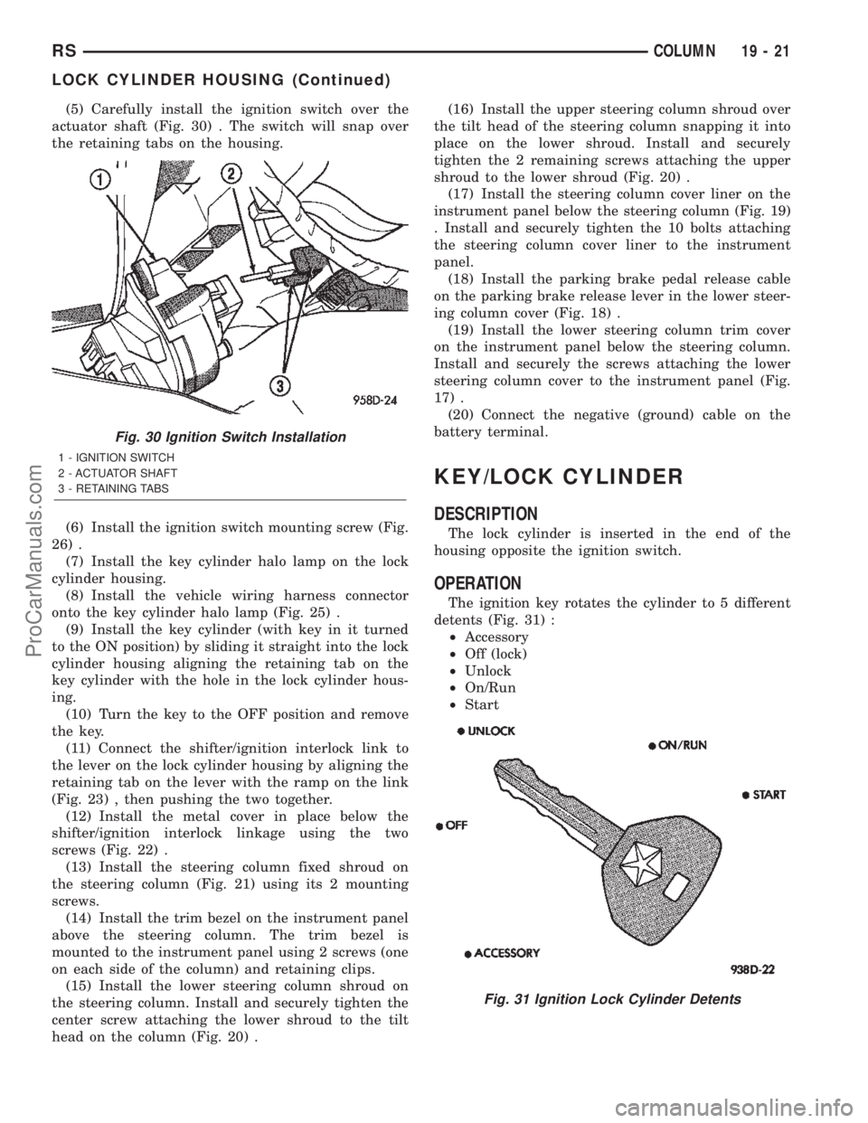
(5) Carefully install the ignition switch over the
actuator shaft (Fig. 30) . The switch will snap over
the retaining tabs on the housing.
(6) Install the ignition switch mounting screw (Fig.
26) .
(7) Install the key cylinder halo lamp on the lock
cylinder housing.
(8) Install the vehicle wiring harness connector
onto the key cylinder halo lamp (Fig. 25) .
(9) Install the key cylinder (with key in it turned
to the ON position) by sliding it straight into the lock
cylinder housing aligning the retaining tab on the
key cylinder with the hole in the lock cylinder hous-
ing.
(10) Turn the key to the OFF position and remove
the key.
(11) Connect the shifter/ignition interlock link to
the lever on the lock cylinder housing by aligning the
retaining tab on the lever with the ramp on the link
(Fig. 23) , then pushing the two together.
(12) Install the metal cover in place below the
shifter/ignition interlock linkage using the two
screws (Fig. 22) .
(13) Install the steering column fixed shroud on
the steering column (Fig. 21) using its 2 mounting
screws.
(14) Install the trim bezel on the instrument panel
above the steering column. The trim bezel is
mounted to the instrument panel using 2 screws (one
on each side of the column) and retaining clips.
(15) Install the lower steering column shroud on
the steering column. Install and securely tighten the
center screw attaching the lower shroud to the tilt
head on the column (Fig. 20) .(16) Install the upper steering column shroud over
the tilt head of the steering column snapping it into
place on the lower shroud. Install and securely
tighten the 2 remaining screws attaching the upper
shroud to the lower shroud (Fig. 20) .
(17) Install the steering column cover liner on the
instrument panel below the steering column (Fig. 19)
. Install and securely tighten the 10 bolts attaching
the steering column cover liner to the instrument
panel.
(18) Install the parking brake pedal release cable
on the parking brake release lever in the lower steer-
ing column cover (Fig. 18) .
(19) Install the lower steering column trim cover
on the instrument panel below the steering column.
Install and securely the screws attaching the lower
steering column cover to the instrument panel (Fig.
17) .
(20) Connect the negative (ground) cable on the
battery terminal.
KEY/LOCK CYLINDER
DESCRIPTION
The lock cylinder is inserted in the end of the
housing opposite the ignition switch.
OPERATION
The ignition key rotates the cylinder to 5 different
detents (Fig. 31) :
²Accessory
²Off (lock)
²Unlock
²On/Run
²Start
Fig. 30 Ignition Switch Installation
1 - IGNITION SWITCH
2 - ACTUATOR SHAFT
3 - RETAINING TABS
Fig. 31 Ignition Lock Cylinder Detents
RSCOLUMN19-21
LOCK CYLINDER HOUSING (Continued)
ProCarManuals.com