radiator CHRYSLER CARAVAN 2002 Service Manual
[x] Cancel search | Manufacturer: CHRYSLER, Model Year: 2002, Model line: CARAVAN, Model: CHRYSLER CARAVAN 2002Pages: 2399, PDF Size: 57.96 MB
Page 2325 of 2399
INSTALLATION
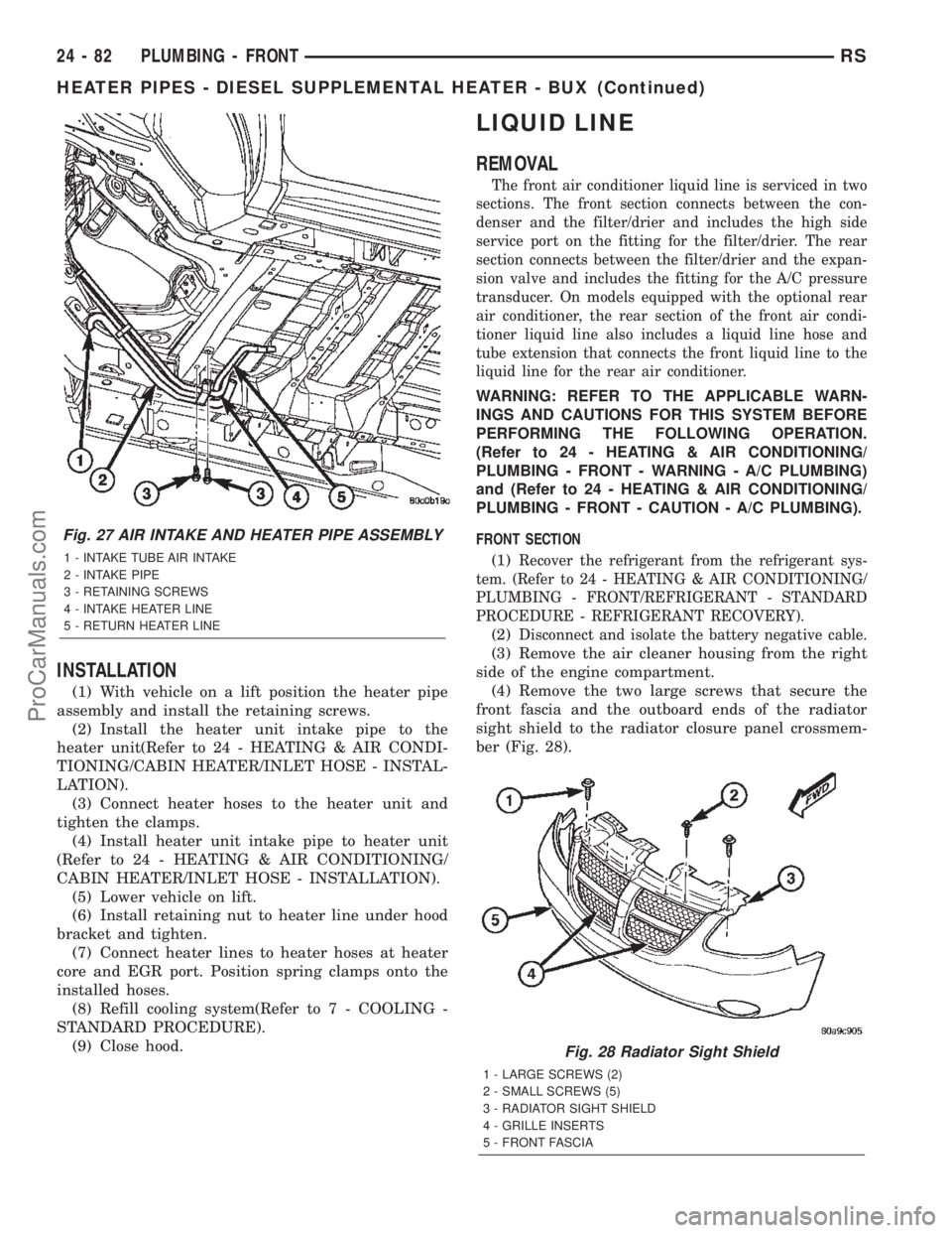
(1) With vehicle on a lift position the heater pipe
assembly and install the retaining screws.
(2) Install the heater unit intake pipe to the
heater unit(Refer to 24 - HEATING & AIR CONDI-
TIONING/CABIN HEATER/INLET HOSE - INSTAL-
LATION).
(3) Connect heater hoses to the heater unit and
tighten the clamps.
(4) Install heater unit intake pipe to heater unit
(Refer to 24 - HEATING & AIR CONDITIONING/
CABIN HEATER/INLET HOSE - INSTALLATION).
(5) Lower vehicle on lift.
(6) Install retaining nut to heater line under hood
bracket and tighten.
(7) Connect heater lines to heater hoses at heater
core and EGR port. Position spring clamps onto the
installed hoses.
(8) Refill cooling system(Refer to 7 - COOLING -
STANDARD PROCEDURE).
(9) Close hood.
LIQUID LINE
REMOVAL
The front air conditioner liquid line is serviced in two
sections. The front section connects between the con-
denser and the filter/drier and includes the high side
service port on the fitting for the filter/drier. The rear
section connects between the filter/drier and the expan-
sion valve and includes the fitting for the A/C pressure
transducer. On models equipped with the optional rear
air conditioner, the rear section of the front air condi-
tioner liquid line also includes a liquid line hose and
tube extension that connects the front liquid line to the
liquid line for the rear air conditioner.
WARNING: REFER TO THE APPLICABLE WARN-
INGS AND CAUTIONS FOR THIS SYSTEM BEFORE
PERFORMING THE FOLLOWING OPERATION.
(Refer to 24 - HEATING & AIR CONDITIONING/
PLUMBING - FRONT - WARNING - A/C PLUMBING)
and (Refer to 24 - HEATING & AIR CONDITIONING/
PLUMBING - FRONT - CAUTION - A/C PLUMBING).
FRONT SECTION
(1)
Recover the refrigerant from the refrigerant sys-
tem. (Refer to 24 - HEATING & AIR CONDITIONING/
PLUMBING - FRONT/REFRIGERANT - STANDARD
PROCEDURE - REFRIGERANT RECOVERY).
(2)Disconnect and isolate the battery negative cable.
(3) Remove the air cleaner housing from the right
side of the engine compartment.
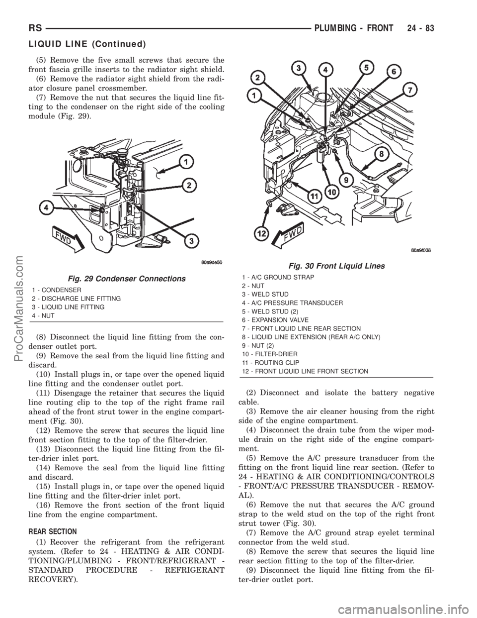
(4) Remove the two large screws that secure the
front fascia and the outboard ends of the radiator
sight shield to the radiator closure panel crossmem-
ber (Fig. 28).
Fig. 27 AIR INTAKE AND HEATER PIPE ASSEMBLY
1 - INTAKE TUBE AIR INTAKE
2 - INTAKE PIPE
3 - RETAINING SCREWS
4 - INTAKE HEATER LINE
5 - RETURN HEATER LINE
Fig. 28 Radiator Sight Shield
1 - LARGE SCREWS (2)
2 - SMALL SCREWS (5)
3 - RADIATOR SIGHT SHIELD
4 - GRILLE INSERTS
5 - FRONT FASCIA
24 - 82 PLUMBING - FRONTRS
HEATER PIPES - DIESEL SUPPLEMENTAL HEATER - BUX (Continued)
ProCarManuals.com
Page 2326 of 2399
(5) Remove the five small screws that secure the
front fascia grille inserts to the radiator sight shield.
(6) Remove the radiator sight shield from the radi-
ator closure panel crossmember.
(7) Remove the nut that secures the liquid line fit-
ting to the condenser on the right side of the cooling
module (Fig. 29).
(8) Disconnect the liquid line fitting from the con-
denser outlet port.
(9) Remove the seal from the liquid line fitting and
discard.
(10) Install plugs in, or tape over the opened liquid
line fitting and the condenser outlet port.
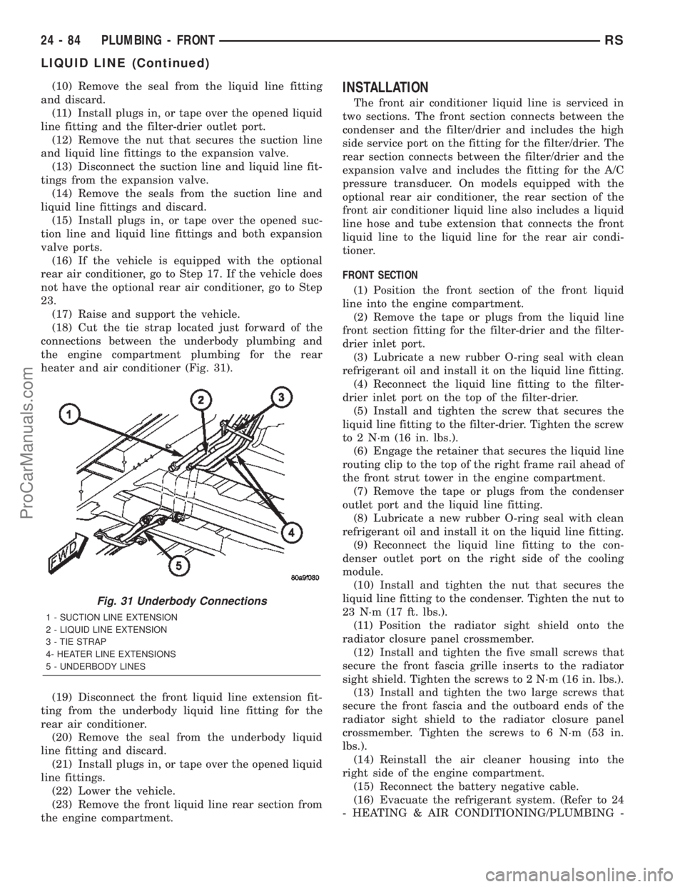
(11) Disengage the retainer that secures the liquid
line routing clip to the top of the right frame rail
ahead of the front strut tower in the engine compart-
ment (Fig. 30).
(12) Remove the screw that secures the liquid line
front section fitting to the top of the filter-drier.
(13) Disconnect the liquid line fitting from the fil-
ter-drier inlet port.
(14) Remove the seal from the liquid line fitting
and discard.
(15) Install plugs in, or tape over the opened liquid
line fitting and the filter-drier inlet port.
(16) Remove the front section of the front liquid
line from the engine compartment.
REAR SECTION
(1) Recover the refrigerant from the refrigerant
system. (Refer to 24 - HEATING & AIR CONDI-
TIONING/PLUMBING - FRONT/REFRIGERANT -
STANDARD PROCEDURE - REFRIGERANT
RECOVERY).(2) Disconnect and isolate the battery negative
cable.
(3) Remove the air cleaner housing from the right
side of the engine compartment.
(4) Disconnect the drain tube from the wiper mod-
ule drain on the right side of the engine compart-
ment.
(5) Remove the A/C pressure transducer from the
fitting on the front liquid line rear section. (Refer to
24 - HEATING & AIR CONDITIONING/CONTROLS
- FRONT/A/C PRESSURE TRANSDUCER - REMOV-
AL).
(6) Remove the nut that secures the A/C ground
strap to the weld stud on the top of the right front
strut tower (Fig. 30).
(7) Remove the A/C ground strap eyelet terminal
connector from the weld stud.
(8) Remove the screw that secures the liquid line
rear section fitting to the top of the filter-drier.
(9) Disconnect the liquid line fitting from the fil-
ter-drier outlet port.
Fig. 29 Condenser Connections
1 - CONDENSER
2 - DISCHARGE LINE FITTING
3 - LIQUID LINE FITTING
4 - NUT
Fig. 30 Front Liquid Lines
1 - A/C GROUND STRAP
2 - NUT
3 - WELD STUD
4 - A/C PRESSURE TRANSDUCER
5 - WELD STUD (2)
6 - EXPANSION VALVE
7 - FRONT LIQUID LINE REAR SECTION
8 - LIQUID LINE EXTENSION (REAR A/C ONLY)
9 - NUT (2)
10 - FILTER-DRIER
11 - ROUTING CLIP
12 - FRONT LIQUID LINE FRONT SECTION
RSPLUMBING - FRONT24-83
LIQUID LINE (Continued)
ProCarManuals.com
Page 2327 of 2399
(10) Remove the seal from the liquid line fitting
and discard.
(11) Install plugs in, or tape over the opened liquid
line fitting and the filter-drier outlet port.
(12) Remove the nut that secures the suction line
and liquid line fittings to the expansion valve.
(13) Disconnect the suction line and liquid line fit-
tings from the expansion valve.
(14) Remove the seals from the suction line and
liquid line fittings and discard.
(15) Install plugs in, or tape over the opened suc-
tion line and liquid line fittings and both expansion
valve ports.
(16) If the vehicle is equipped with the optional
rear air conditioner, go to Step 17. If the vehicle does
not have the optional rear air conditioner, go to Step
23.
(17) Raise and support the vehicle.
(18) Cut the tie strap located just forward of the
connections between the underbody plumbing and
the engine compartment plumbing for the rear
heater and air conditioner (Fig. 31).
(19) Disconnect the front liquid line extension fit-
ting from the underbody liquid line fitting for the
rear air conditioner.
(20) Remove the seal from the underbody liquid
line fitting and discard.
(21) Install plugs in, or tape over the opened liquid
line fittings.
(22) Lower the vehicle.
(23) Remove the front liquid line rear section from
the engine compartment.INSTALLATION
The front air conditioner liquid line is serviced in
two sections. The front section connects between the
condenser and the filter/drier and includes the high
side service port on the fitting for the filter/drier. The
rear section connects between the filter/drier and the
expansion valve and includes the fitting for the A/C
pressure transducer. On models equipped with the
optional rear air conditioner, the rear section of the
front air conditioner liquid line also includes a liquid
line hose and tube extension that connects the front
liquid line to the liquid line for the rear air condi-
tioner.
FRONT SECTION
(1) Position the front section of the front liquid
line into the engine compartment.
(2) Remove the tape or plugs from the liquid line
front section fitting for the filter-drier and the filter-
drier inlet port.
(3) Lubricate a new rubber O-ring seal with clean
refrigerant oil and install it on the liquid line fitting.
(4) Reconnect the liquid line fitting to the filter-
drier inlet port on the top of the filter-drier.
(5) Install and tighten the screw that secures the
liquid line fitting to the filter-drier. Tighten the screw
to 2 N´m (16 in. lbs.).
(6) Engage the retainer that secures the liquid line
routing clip to the top of the right frame rail ahead of
the front strut tower in the engine compartment.
(7) Remove the tape or plugs from the condenser
outlet port and the liquid line fitting.
(8) Lubricate a new rubber O-ring seal with clean
refrigerant oil and install it on the liquid line fitting.
(9) Reconnect the liquid line fitting to the con-
denser outlet port on the right side of the cooling
module.
(10) Install and tighten the nut that secures the
liquid line fitting to the condenser. Tighten the nut to
23 N´m (17 ft. lbs.).
(11) Position the radiator sight shield onto the
radiator closure panel crossmember.
(12) Install and tighten the five small screws that
secure the front fascia grille inserts to the radiator
sight shield. Tighten the screws to 2 N´m (16 in. lbs.).
(13) Install and tighten the two large screws that
secure the front fascia and the outboard ends of the
radiator sight shield to the radiator closure panel
crossmember. Tighten the screws to 6 N´m (53 in.
lbs.).
(14) Reinstall the air cleaner housing into the
right side of the engine compartment.
(15) Reconnect the battery negative cable.
(16) Evacuate the refrigerant system. (Refer to 24
- HEATING & AIR CONDITIONING/PLUMBING -
Fig. 31 Underbody Connections
1 - SUCTION LINE EXTENSION
2 - LIQUID LINE EXTENSION
3 - TIE STRAP
4- HEATER LINE EXTENSIONS
5 - UNDERBODY LINES
24 - 84 PLUMBING - FRONTRS
LIQUID LINE (Continued)
ProCarManuals.com
Page 2344 of 2399
INSTALLATION
(1) Remove the tape or plugs from the evaporator
tube fittings and both expansion valve ports.
(2) Lubricate new rubber O-ring seals with clean
refrigerant oil and install them on the evaporator
tube fittings.
(3) Position the expansion valve onto the evapora-
tor tubes.
(4) Install and tighten the two screws that secure
the expansion valve to the evaporator tube sealing
plate. Tighten the screws to 11 N´m (97 in. lbs.).
(5) Reinstall the rear evaporator line extension
onto the expansion valve. (Refer to 24 - HEATING &
AIR CONDITIONING/PLUMBING - REAR/EVAPO-
RATOR - INSTALLATION - EVAPORATOR LINE
EXTENSION).
(6) Install the foam insulator wrap over the rear
expansion valve.
(7) Reinstall the rear heater-A/C unit housing into
the vehicle. (Refer to 24 - HEATING & AIR CONDI-
TIONING/DISTRIBUTION - REAR/REAR HEATER-
A/C HOUSING - INSTALLATION).
(8) Run the HVAC Cooldown Test to verify proper
operation.
HEATER CORE
DESCRIPTION
The rear heater core is located near the front of
the rear heater-A/C unit housing, behind the right
rear wheel house. It is a heat exchanger made of
rows of tubes and fins. One end of the core is fitted
with a molded plastic tank that includes integral
heater core inlet and outlet nipples. The heater core
can be serviced without removing the rear heater-A/C
unit housing from the vehicle. The heater core cannot
be repaired and, if faulty or damaged, it must be
replaced.
OPERATION
Engine coolant is circulated through heater hoses
to the heater core at all times. As the coolant flows
through the heater core, heat removed from the
engine is transferred to the heater core fins and
tubes. Air directed through the heater core picks up
the heat from the heater core fins. The blend air door
allows control of the heater output air temperature
by controlling how much of the air flowing through
the rear heater-A/C unit housing is directed through
the heater core.
STANDARD PROCEDURE - HEATER CORE
FILLING
In its final installed position, the rear heater core
is positioned higher than the radiator fill cap. There-fore, when the cooling system is drained and refilled,
gravity will not refill the heater core with coolant to
the proper level. This may result in two problems:1.
Insufficient coolant level in the engine cooling sys-
tem, which may result in engine overheating.2.Air
entrapped within the rear heater core, which may
result in insufficient rear heater performance. There
are two methods that may be employed to prevent
these problems:1.Pre-filling of the rear heater core.
2.Thermal cycling of the engine cooling system. Fol-
lowing are descriptions of both prevention methods,
as well as a method to verify rear heater perfor-
mance.
WARNING: REFER TO THE APPLICABLE WARN-
INGS AND CAUTIONS FOR THIS SYSTEM BEFORE
PERFORMING THE FOLLOWING OPERATION.
(Refer to 24 - HEATING & AIR CONDITIONING/
PLUMBING FRONT - WARNING - HEATER PLUMB-
ING).
PRE-FILLING
If the rear heater core or the rear heater-A/C hous-
ing have been removed from the vehicle for service,
the rear heater core may be pre-filled with the proper
engine coolant mixture prior to reconnecting the
heater hoses to the heater core hose fittings.
(1) The heater core should be installed in the rear
heater-A/C unit housing, and the rear heater-A/C
unit housing should be installed in the vehicle.
(2) Take the proper precautions to protect the car-
peting below the rear heater core from spilled engine
coolant and have absorbent toweling readily avail-
able to mop up any spills.
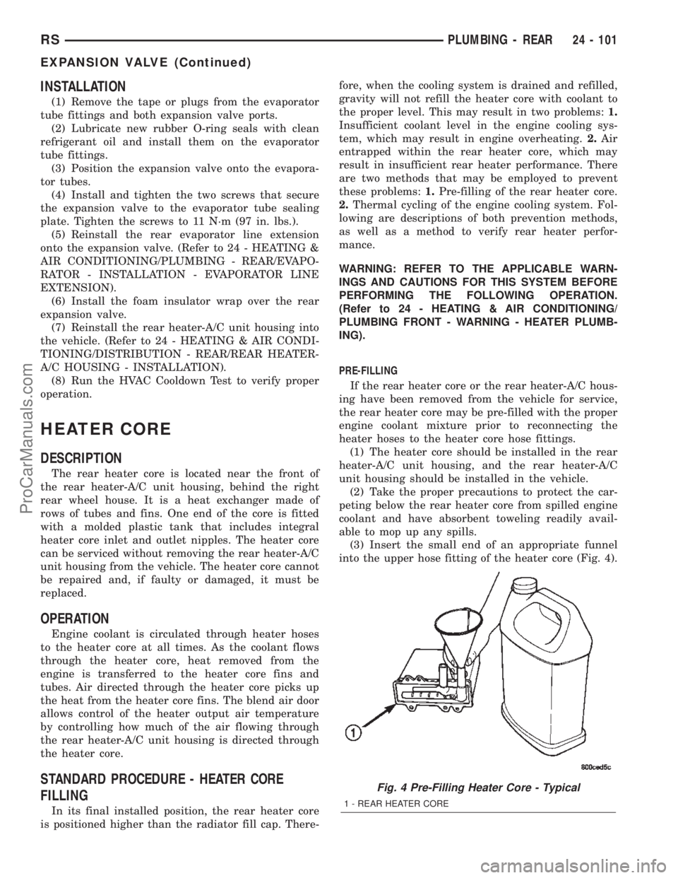
(3) Insert the small end of an appropriate funnel
into the upper hose fitting of the heater core (Fig. 4).
Fig. 4 Pre-Filling Heater Core - Typical
1 - REAR HEATER CORE
RSPLUMBING - REAR24 - 101
EXPANSION VALVE (Continued)
ProCarManuals.com
Page 2361 of 2399
The following is a list of the monitored compo-
nents:
²Comprehensive Components
²Oxygen Sensor Monitor
²Oxygen Sensor Heater Monitor
²Catalyst Monitor
COMPREHENSIVE COMPONENTS
Along with the major monitors, OBD II requires
that the diagnostic system monitor any component
that could affect emissions levels. In many cases,
these components were being tested under OBD I.
The OBD I requirements focused mainly on testing
emissions-related components for electrical opens and
shorts.
However, OBD II also requires that inputs from
powertrain components to the PCM be tested for
rationality, and that outputs to powertrain compo-
nents from the PCM be tested forfunctionality.
Methods for monitoring the various Comprehensive
Component monitoring include:
(1) Circuit Continuity
²Open
²Shorted high
²Shorted to ground
(2) Rationality or Proper Functioning
²Inputs tested for rationality
²Outputs tested for functionality
NOTE: Comprehensive component monitors are
continuous. Therefore, enabling conditions do not
apply.
Input RationalityÐWhile input signals to the
PCM are constantly being monitored for electrical
opens and shorts, they are also tested for rationality.
This means that the input signal is compared against
other inputs and information to see if it makes sense
under the current conditions.
PCM sensor inputs that are checked for rationality
include:
²Manifold Absolute Pressure (MAP) Sensor
²Oxygen Sensor (O2S)
²Engine Coolant Temperature (ECT) Sensor
²Camshaft Position (CMP) Sensor
²Vehicle Speed Sensor
²Crankshaft Position (CKP) Sensor
²Intake/inlet Air Temperature (IAT) Sensor
²Throttle Position (TPS) Sensor
²Ambient/Battery Temperature Sensors
²Power Steering Switch
²Oxygen Sensor Heater
²Engine Controller
²Brake Switch
²Leak Detection Pump Switch (if equipped)
²P/N Switch
²Trans ControlsOutput FunctionalityÐPCM outputs are tested
for functionality in addition to testing for opens and
shorts. When the PCM provides a voltage to an out-
put component, it can verify that the command was
carried out by monitoring specific input signals for
expected changes. For example, when the PCM com-
mands the Idle Air Control (IAC) Motor to a specific
position under certain operating conditions, it expects
to see a specific (target) idle speed (RPM). If it does
not, it stores a DTC.
PCM outputs monitored for functionality include:
²Fuel Injectors
²Ignition Coils
²Torque Converter Clutch Solenoid
²Idle Air Control
²Purge Solenoid
²EGR Solenoid (if equipped)
²LDP Solenoid (if equipped)
²Radiator Fan Control
²Trans Controls
OXYGEN SENSOR (O2S) MONITOR
DESCRIPTIONÐEffective control of exhaust
emissions is achieved by an oxygen feedback system.
The most important element of the feedback system
is the O2S. The O2S is located in the exhaust path.
Once it reaches operating temperature 300É to 350ÉC
(572É to 662ÉF), the sensor generates a voltage that
is inversely proportional to the amount of oxygen in
the exhaust. When there is a large amount of oxygen
in the exhaust caused by a lean condition, the sensor
produces a low voltage, below 450 mV. When the oxy-
gen content is lower, caused by a rich condition, the
sensor produces a higher voltage, above 450mV.
The information obtained by the sensor is used to
calculate the fuel injector pulse width. The PCM is
programmed to maintain the optimum air/fuel ratio.
At this mixture ratio, the catalyst works best to
remove hydrocarbons (HC), carbon monoxide (CO)
and nitrous oxide (NOx) from the exhaust.
The O2S is also the main sensing element for the
EGR (if equipped), Catalyst and Fuel Monitors.
The O2S may fail in any or all of the following
manners:
²Slow response rate (Big Slope)
²Reduced output voltage (Half Cycle)
²Heater Performance
Slow Response Rate (Big Slope)ÐResponse rate
is the time required for the sensor to switch from
lean to rich signal output once it is exposed to a
richer than optimum A/F mixture or vice versa. As
the PCM adjusts the air/fuel ratio, the sensor must
be able to rapidly detect the change. As the sensor
ages, it could take longer to detect the changes in the
oxygen content of the exhaust gas. The rate of
change that an oxygen sensor experiences is called
25 - 2 EMISSIONS CONTROLRS
EMISSIONS CONTROL (Continued)
ProCarManuals.com