tire pressure CHRYSLER CARAVAN 2002 Service Manual
[x] Cancel search | Manufacturer: CHRYSLER, Model Year: 2002, Model line: CARAVAN, Model: CHRYSLER CARAVAN 2002Pages: 2399, PDF Size: 57.96 MB
Page 35 of 2399
(4) Wipe any grease off the ball joint stem using a
clean shop towel with MopartBrake Parts Cleaner
applied to it.
CAUTION: Do not attempt to install a normal grease
zirc in the ball joint an lubricate the joint through
the zirc fitting.
(5) Reinstall steering knuckle on vehicle. (Refer to
2 - SUSPENSION/FRONT/KNUCKLE - INSTALLA-
TION)
INSTALLATION - EXPORT
(1) Place a liberal dab of MopartWheel Bearing
Grease around the base of the ball joint stem at the
socket.
(2) Install aNEWseal boot by hand as far as pos-
sible on the ball joint.
CAUTION: Do not use an arbor press to install the
sealing boot on the ball joint. Damage to the seal-
ing boot will occur if excessive pressure is applied
to the sealing boot when it is being installed.
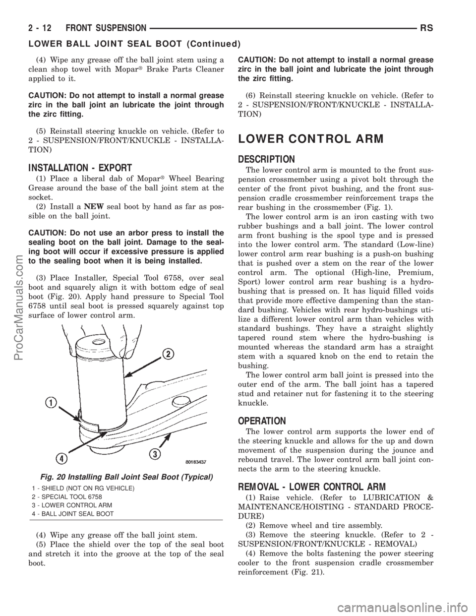
(3) Place Installer, Special Tool 6758, over seal
boot and squarely align it with bottom edge of seal
boot (Fig. 20). Apply hand pressure to Special Tool
6758 until seal boot is pressed squarely against top
surface of lower control arm.
(4) Wipe any grease off the ball joint stem.
(5) Place the shield over the top of the seal boot
and stretch it into the groove at the top of the seal
boot.CAUTION: Do not attempt to install a normal grease
zirc in the ball joint and lubricate the joint through
the zirc fitting.
(6) Reinstall steering knuckle on vehicle. (Refer to
2 - SUSPENSION/FRONT/KNUCKLE - INSTALLA-
TION)
LOWER CONTROL ARM
DESCRIPTION
The lower control arm is mounted to the front sus-
pension crossmember using a pivot bolt through the
center of the front pivot bushing, and the front sus-
pension cradle crossmember reinforcement traps the
rear bushing in the crossmember (Fig. 1).
The lower control arm is an iron casting with two
rubber bushings and a ball joint. The lower control
arm front bushing is the spool type and is pressed
into the lower control arm. The standard (Low-line)
lower control arm rear bushing is a push-on bushing
that is pushed over a stem on the rear of the lower
control arm. The optional (High-line, Premium,
Sport) lower control arm rear bushing is a hydro-
bushing that is pressed on. It has liquid filled voids
that provide more effective dampening than the stan-
dard bushing. Vehicles with rear hydro-bushings uti-
lize a different lower control arm than vehicles with
standard bushings. They have a straight slightly
tapered round stem where the hydro-bushing is
mounted whereas the standard arm has a straight
stem with a squared knob on the end to retain the
bushing.
The lower control arm ball joint is pressed into the
outer end of the arm. The ball joint has a tapered
stud and retainer nut for fastening it to the steering
knuckle.
OPERATION
The lower control arm supports the lower end of
the steering knuckle and allows for the up and down
movement of the suspension during the jounce and
rebound travel. The lower control arm ball joint con-
nects the arm to the steering knuckle.
REMOVAL - LOWER CONTROL ARM
(1) Raise vehicle. (Refer to LUBRICATION &
MAINTENANCE/HOISTING - STANDARD PROCE-
DURE)
(2) Remove wheel and tire assembly.
(3) Remove the steering knuckle. (Refer to 2 -
SUSPENSION/FRONT/KNUCKLE - REMOVAL)
(4) Remove the bolts fastening the power steering
cooler to the front suspension cradle crossmember
reinforcement (Fig. 21).
Fig. 20 Installing Ball Joint Seal Boot (Typical)
1 - SHIELD (NOT ON RG VEHICLE)
2 - SPECIAL TOOL 6758
3 - LOWER CONTROL ARM
4 - BALL JOINT SEAL BOOT
2 - 12 FRONT SUSPENSIONRS
LOWER BALL JOINT SEAL BOOT (Continued)
ProCarManuals.com
Page 73 of 2399
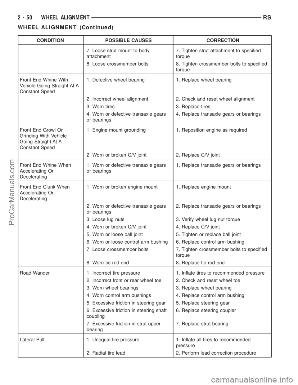
CONDITION POSSIBLE CAUSES CORRECTION
7. Loose strut mount to body
attachment7. Tighten strut attachment to specified
torque
8. Loose crossmember bolts 8. Tighten crossmember bolts to specified
torque
Front End Whine With
Vehicle Going Straight At A
Constant Speed1. Defective wheel bearing 1. Replace wheel bearing
2. Incorrect wheel alignment 2. Check and reset wheel alignment
3. Worn tires 3. Replace tires
4. Worn or defective transaxle gears
or bearings4. Replace transaxle gears or bearings
Front End Growl Or
Grinding With Vehicle
Going Straight At A
Constant Speed1. Engine mount grounding 1. Reposition engine as required
2. Worn or broken C/V joint 2. Replace C/V joint
Front End Whine When
Accelerating Or
Decelerating1. Worn or defective transaxle gears
or bearings1. Replace transaxle gears or bearings
Front End Clunk When
Accelerating Or
Decelerating1. Worn or broken engine mount 1. Replace engine mount
2. Worn or defective transaxle gears
or bearings2. Replace transaxle gears or bearings
3. Loose lug nuts 3. Verify wheel lug nut torque
4. Worn or broken C/V joint 4. Replace C/V joint
5. Worn or loose ball joint 5. Tighten or replace ball joint
6. Worn or loose control arm bushing 6. Replace control arm bushing
7. Loose crossmember bolts 7. Tighten crossmember bolts to specified
torque
8. Worn tie rod end 8. Replace tie rod end
Road Wander 1. Incorrect tire pressure 1. Inflate tires to recommended pressure
2. Incorrect front or rear wheel toe 2. Check and reset wheel toe
3. Worn wheel bearings 3. Replace wheel bearing
4. Worn control arm bushings 4. Replace control arm bushing
5. Excessive friction in steering gear 5. Replace steering gear
6. Excessive friction in steering shaft
coupling6. Replace steering coupler
7. Excessive friction in strut upper
bearing7. Replace strut bearing
Lateral Pull 1. Unequal tire pressure 1. Inflate all tires to recommended
pressure
2. Radial tire lead 2. Perform lead correction procedure
2 - 50 WHEEL ALIGNMENTRS
WHEEL ALIGNMENT (Continued)
ProCarManuals.com
Page 74 of 2399
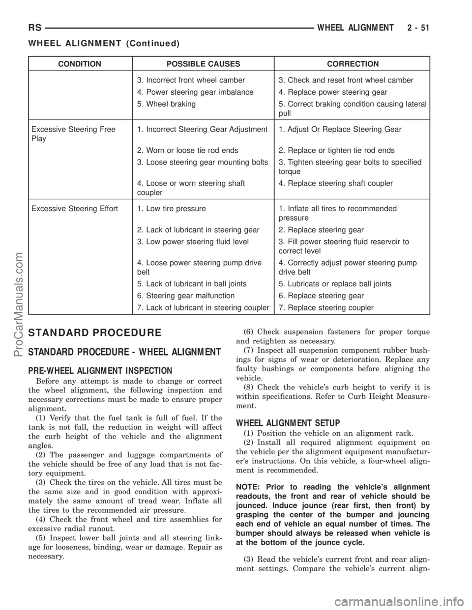
CONDITION POSSIBLE CAUSES CORRECTION
3. Incorrect front wheel camber 3. Check and reset front wheel camber
4. Power steering gear imbalance 4. Replace power steering gear
5. Wheel braking 5. Correct braking condition causing lateral
pull
Excessive Steering Free
Play1. Incorrect Steering Gear Adjustment 1. Adjust Or Replace Steering Gear
2. Worn or loose tie rod ends 2. Replace or tighten tie rod ends
3. Loose steering gear mounting bolts 3. Tighten steering gear bolts to specified
torque
4. Loose or worn steering shaft
coupler4. Replace steering shaft coupler
Excessive Steering Effort 1. Low tire pressure 1. Inflate all tires to recommended
pressure
2. Lack of lubricant in steering gear 2. Replace steering gear
3. Low power steering fluid level 3. Fill power steering fluid reservoir to
correct level
4. Loose power steering pump drive
belt4. Correctly adjust power steering pump
drive belt
5. Lack of lubricant in ball joints 5. Lubricate or replace ball joints
6. Steering gear malfunction 6. Replace steering gear
7. Lack of lubricant in steering coupler 7. Replace steering coupler
STANDARD PROCEDURE
STANDARD PROCEDURE - WHEEL ALIGNMENT
PRE-WHEEL ALIGNMENT INSPECTION
Before any attempt is made to change or correct
the wheel alignment, the following inspection and
necessary corrections must be made to ensure proper
alignment.
(1) Verify that the fuel tank is full of fuel. If the
tank is not full, the reduction in weight will affect
the curb height of the vehicle and the alignment
angles.
(2) The passenger and luggage compartments of
the vehicle should be free of any load that is not fac-
tory equipment.
(3) Check the tires on the vehicle. All tires must be
the same size and in good condition with approxi-
mately the same amount of tread wear. Inflate all
the tires to the recommended air pressure.
(4) Check the front wheel and tire assemblies for
excessive radial runout.
(5) Inspect lower ball joints and all steering link-
age for looseness, binding, wear or damage. Repair as
necessary.(6) Check suspension fasteners for proper torque
and retighten as necessary.
(7) Inspect all suspension component rubber bush-
ings for signs of wear or deterioration. Replace any
faulty bushings or components before aligning the
vehicle.
(8) Check the vehicle's curb height to verify it is
within specifications. Refer to Curb Height Measure-
ment.
WHEEL ALIGNMENT SETUP
(1) Position the vehicle on an alignment rack.
(2) Install all required alignment equipment on
the vehicle per the alignment equipment manufactur-
er's instructions. On this vehicle, a four-wheel align-
ment is recommended.
NOTE: Prior to reading the vehicle's alignment
readouts, the front and rear of vehicle should be
jounced. Induce jounce (rear first, then front) by
grasping the center of the bumper and jouncing
each end of vehicle an equal number of times. The
bumper should always be released when vehicle is
at the bottom of the jounce cycle.
(3) Read the vehicle's current front and rear align-
ment settings. Compare the vehicle's current align-
RSWHEEL ALIGNMENT2-51
WHEEL ALIGNMENT (Continued)
ProCarManuals.com
Page 77 of 2399
CAUTION: Do not twist front inner tie rod to steer-
ing gear rubber boots during front wheel Toe
adjustment.
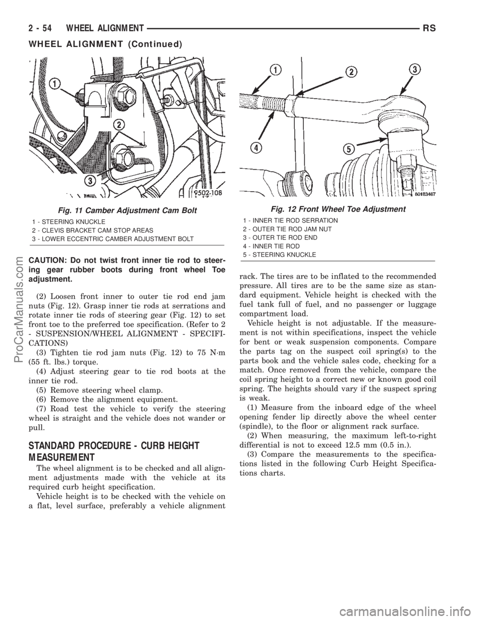
(2) Loosen front inner to outer tie rod end jam
nuts (Fig. 12). Grasp inner tie rods at serrations and
rotate inner tie rods of steering gear (Fig. 12) to set
front toe to the preferred toe specification. (Refer to 2
- SUSPENSION/WHEEL ALIGNMENT - SPECIFI-
CATIONS)
(3) Tighten tie rod jam nuts (Fig. 12) to 75 N´m
(55 ft. lbs.) torque.
(4) Adjust steering gear to tie rod boots at the
inner tie rod.
(5) Remove steering wheel clamp.
(6) Remove the alignment equipment.
(7) Road test the vehicle to verify the steering
wheel is straight and the vehicle does not wander or
pull.
STANDARD PROCEDURE - CURB HEIGHT
MEASUREMENT
The wheel alignment is to be checked and all align-
ment adjustments made with the vehicle at its
required curb height specification.
Vehicle height is to be checked with the vehicle on
a flat, level surface, preferably a vehicle alignmentrack. The tires are to be inflated to the recommended
pressure. All tires are to be the same size as stan-
dard equipment. Vehicle height is checked with the
fuel tank full of fuel, and no passenger or luggage
compartment load.
Vehicle height is not adjustable. If the measure-
ment is not within specifications, inspect the vehicle
for bent or weak suspension components. Compare
the parts tag on the suspect coil spring(s) to the
parts book and the vehicle sales code, checking for a
match. Once removed from the vehicle, compare the
coil spring height to a correct new or known good coil
spring. The heights should vary if the suspect spring
is weak.
(1) Measure from the inboard edge of the wheel
opening fender lip directly above the wheel center
(spindle), to the floor or alignment rack surface.
(2) When measuring, the maximum left-to-right
differential is not to exceed 12.5 mm (0.5 in.).
(3) Compare the measurements to the specifica-
tions listed in the following Curb Height Specifica-
tions charts.
Fig. 11 Camber Adjustment Cam Bolt
1 - STEERING KNUCKLE
2 - CLEVIS BRACKET CAM STOP AREAS
3 - LOWER ECCENTRIC CAMBER ADJUSTMENT BOLT
Fig. 12 Front Wheel Toe Adjustment
1 - INNER TIE ROD SERRATION
2 - OUTER TIE ROD JAM NUT
3 - OUTER TIE ROD END
4 - INNER TIE ROD
5 - STEERING KNUCKLE
2 - 54 WHEEL ALIGNMENTRS
WHEEL ALIGNMENT (Continued)
ProCarManuals.com
Page 78 of 2399
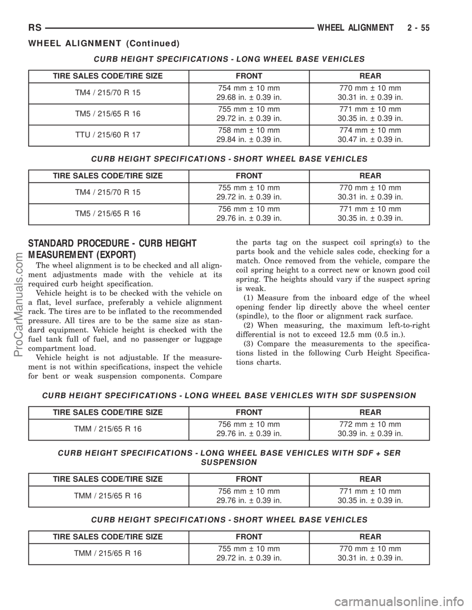
CURB HEIGHT SPECIFICATIONS - LONG WHEEL BASE VEHICLES
TIRE SALES CODE/TIRE SIZE FRONT REAR
TM4 / 215/70 R 15754mm 10mm
29.68 in. 0.39 in.770mm 10mm
30.31 in. 0.39 in.
TM5 / 215/65 R 16755mm 10mm
29.72 in. 0.39 in.771mm 10mm
30.35 in. 0.39 in.
TTU / 215/60 R 17758mm 10mm
29.84 in. 0.39 in.774mm 10mm
30.47 in. 0.39 in.
CURB HEIGHT SPECIFICATIONS - SHORT WHEEL BASE VEHICLES
TIRE SALES CODE/TIRE SIZE FRONT REAR
TM4 / 215/70 R 15755mm 10mm
29.72 in. 0.39 in.770mm 10mm
30.31 in. 0.39 in.
TM5 / 215/65 R 16756mm 10mm
29.76 in. 0.39 in.771mm 10mm
30.35 in. 0.39 in.
STANDARD PROCEDURE - CURB HEIGHT
MEASUREMENT (EXPORT)
The wheel alignment is to be checked and all align-
ment adjustments made with the vehicle at its
required curb height specification.
Vehicle height is to be checked with the vehicle on
a flat, level surface, preferably a vehicle alignment
rack. The tires are to be inflated to the recommended
pressure. All tires are to be the same size as stan-
dard equipment. Vehicle height is checked with the
fuel tank full of fuel, and no passenger or luggage
compartment load.
Vehicle height is not adjustable. If the measure-
ment is not within specifications, inspect the vehicle
for bent or weak suspension components. Comparethe parts tag on the suspect coil spring(s) to the
parts book and the vehicle sales code, checking for a
match. Once removed from the vehicle, compare the
coil spring height to a correct new or known good coil
spring. The heights should vary if the suspect spring
is weak.
(1) Measure from the inboard edge of the wheel
opening fender lip directly above the wheel center
(spindle), to the floor or alignment rack surface.
(2) When measuring, the maximum left-to-right
differential is not to exceed 12.5 mm (0.5 in.).
(3) Compare the measurements to the specifica-
tions listed in the following Curb Height Specifica-
tions charts.
CURB HEIGHT SPECIFICATIONS - LONG WHEEL BASE VEHICLES WITH SDF SUSPENSION
TIRE SALES CODE/TIRE SIZE FRONT REAR
TMM / 215/65 R 16756mm 10mm
29.76 in. 0.39 in.772mm 10mm
30.39 in. 0.39 in.
CURB HEIGHT SPECIFICATIONS - LONG WHEEL BASE VEHICLES WITH SDF + SER
SUSPENSION
TIRE SALES CODE/TIRE SIZE FRONT REAR
TMM / 215/65 R 16756mm 10mm
29.76 in. 0.39 in.771mm 10mm
30.35 in. 0.39 in.
CURB HEIGHT SPECIFICATIONS - SHORT WHEEL BASE VEHICLES
TIRE SALES CODE/TIRE SIZE FRONT REAR
TMM / 215/65 R 16755mm 10mm
29.72 in. 0.39 in.770mm 10mm
30.31 in. 0.39 in.
RSWHEEL ALIGNMENT2-55
WHEEL ALIGNMENT (Continued)
ProCarManuals.com
Page 105 of 2399
²Wheel bearings
²Engine
²Transmission
²Exhaust
²Propeller shaft (vibration)
²Vehicle body (drumming)
Driveline module noises are normally divided into
two categories: gear noise or bearing noise. A thor-
ough and careful inspection should be completed to
determine the actual source of the noise before
replacing the driveline module.
The rubber mounting bushings help to dampen-out
driveline module noise when properly installed.
Inspect to confirm that no metal contact exists
between the driveline module case and the body. The
complete isolation of noise to one area requires
expertise and experience. Identifying certain types of
vehicle noise baffles even the most capable techni-
cians. Often such practices as:
²Increase tire inflation pressure to eliminate tire
noise.
²Listen for noise at varying speeds with different
driveline load conditions
²Swerving the vehicle from left to right to detect
wheel bearing noise.
All driveline module assemblies produce noise to a
certain extent. Slight carrier noise that is noticeable
only at certain speeds or isolated situations should be
considered normal. Carrier noise tends to peak at a
variety of vehicle speeds. Noise isNOT ALWAYSan
indication of a problem within the carrier.
TIRE NOISE
Tire noise is often mistaken for driveline module
noise. Tires that are unbalanced, worn unevenly or
are worn in a saw-tooth manner are usually noisy.
They often produce a noise that appears to originate
in the driveline module.
Tire noise changes with different road surfaces, but
driveline module noise does not. Inflate all four tires
with approximately 20 psi (138 kPa) more than the
recommended inflation pressure (for test purposes
only). This will alter noise caused by tires, but will
not affect noise caused by the differential. Rear axle
noise usually ceases when coasting at speeds less
than 30 mph (48 km/h); however, tire noise contin-
ues, but at a lower frequency, as the speed is
reduced.
After test has been completed lower tire pressure
back to recommended pressure.
GEAR NOISE (DRIVE PINION AND RING GEAR)
Abnormal gear noise is rare and is usually caused
by scoring on the ring gear and drive pinion. Scoring
is the result of insufficient or incorrect lubricant in
the carrier housing.Abnormal gear noise can be easily recognized. It
produces a cycling tone that will be very pronounced
within a given speed range. The noise can occur dur-
ing one or more of the following drive conditions:
²Drive
²Road load
²Float
²Coast
Abnormal gear noise usually tends to peak within
a narrow vehicle speed range or ranges. It is usually
more pronounced between 30 to 40 mph (48 to 64
km/h) and 50 to 60 mph (80 to 96 km/h). When objec-
tionable gear noise occurs, note the driving condi-
tions and the speed range.
BEARING NOISE (DRIVE PINION AND
DIFFERENTIAL)
Defective bearings produce a rough growl that is
constant in pitch and varies with the speed of vehi-
cle. Being aware of this will enable a technician to
separate bearing noise from gear noise.
Drive pinion bearing noise that results from defec-
tive or damaged bearings can usually be identified by
its constant, rough sound. Drive pinion front bearing
is usually more pronounced during a coast condition.
Drive pinion rear bearing noise is more pronounced
during a drive condition. The drive pinion bearings
are rotating at a higher rate of speed than either the
differential side bearings or the axle shaft bearing.
Differential side bearing noise will usually produce
a constant, rough sound. The sound is much lower in
frequency than the noise caused by drive pinion bear-
ings.
Bearing noise can best be detected by road testing
the vehicle on a smooth road (black top). However, it
is easy to mistake tire noise for bearing noise. If a
doubt exists, the tire treads should be examined for
irregularities that often causes a noise that resem-
bles bearing noise.
ENGINE AND TRANSMISSION NOISE
Sometimes noise that appears to be in the driv-
eline module assembly is actually caused by the
engine or the transmission. To identify the true
source of the noise, note the approximate vehicle
speed and/or RPM when the noise is most noticeable.
Stop the vehicle next to a flat brick or cement wall
(this will help reflect the sound). Place the transaxle
inNEUTRAL. Accelerate the engine slowly up
through the engine speed that matches the vehicle
speed noted when the noise occurred. If the same
noise is produced, it usually indicates that the noise
is being caused by the engine or transaxle.
3 - 26 REAR DRIVELINE MODULERS
REAR DRIVELINE MODULE (Continued)
ProCarManuals.com
Page 132 of 2399
SUPPORT PLATE - DRUM BRAKE
REMOVAL.............................64
INSTALLATION.........................64
WHEEL CYLINDERS
REMOVAL.............................65
INSPECTION..........................65
INSTALLATION.........................65
PARKING BRAKE
DESCRIPTION
DESCRIPTION........................65
DESCRIPTION - EXPORT...............66
OPERATION...........................66
STANDARD PROCEDURE
STANDARD PROCEDURE - PARKING
BRAKE AUTOMATIC ADJUSTER TENSION
RELEASE...........................66
STANDARD PROCEDURE - PARKING
BRAKE AUTOMATIC ADJUSTER TENSION
RESET.............................67
CABLES - PARKING BRAKE
REMOVAL
REMOVAL - PARKING BRAKE CABLE
(FRONT)............................67
REMOVAL - PARKING BRAKE CABLE
(INTERMEDIATE)......................68
REMOVAL - PARKING BRAKE CABLE
(RIGHT REAR)........................69
REMOVAL - PARKING BRAKE CABLE (LEFT
REAR)..............................70INSTALLATION
INSTALLATION - PARKING BRAKE CABLE
(FRONT)............................71
INSTALLATION - PARKING BRAKE CABLE
(INTERMEDIATE)......................71
INSTALLATION - PARKING BRAKE CABLE
(RIGHT REAR)........................72
INSTALLATION - PARKING BRAKE CABLE
(LEFT REAR).........................72
ADJUSTMENTS
ADJUSTMENT - PARKING BRAKE CABLES . 72
CABLES - PARKING BRAKE (EXPORT)
REMOVAL - FRONT CABLE...............72
INSTALLATION - FRONT CABLE............72
LEVER - PARKING BRAKE
REMOVAL.............................72
INSTALLATION.........................73
LEVER - PARKING BRAKE (EXPORT)
REMOVAL - PARKING BRAKE LEVER AND
FRONT CABLE.......................74
INSTALLATION - PARKING BRAKE LEVER
AND FRONT CABLE...................75
SHOES - PARKING BRAKE
REMOVAL.............................75
INSTALLATION.........................81
ADJUSTMENTS
ADJUSTMENT - PARKING BRAKE SHOES . . 83
BRAKES - BASE
DESCRIPTION
DESCRIPTION - BASE BRAKES
The base brake system consists of the following
components:
²Brake pedal
²Power brake booster
²Master cylinder
²Brake tubes and hoses
²Proportioning valve (non-ABS vehicles only)
²Disc brakes
²Drum brakes
²Brake lamp switch
²Brake fluid level switch
²Parking brakes
Front disc brakes control the braking of the front
wheels; rear braking is controlled by rear drum
brakes or rear disc brakes depending on options.
The hydraulic brake system is diagonally split on
both the non-antilock braking systems and antilock
braking systems. That means the left front and right
rear brakes are on one hydraulic circuit and the right
front and left rear are on the other.For information on the brake lamp switch, (Refer
to 8 - ELECTRICAL/LAMPS/LIGHTING - EXTERI-
OR/BRAKE LAMP SWITCH - DESCRIPTION)
Vehicles equipped with the optional antilock brake
system (ABS) use a system designated Mark 20e. It
is available with or without traction control. This
system shares most base brake hardware used on
vehicles without ABS. ABS components are described
in detail in ANTILOCK BRAKE SYSTEM.
DESCRIPTION - BASE BRAKES (EXPORT)
Four-Wheel Disc Antilock Brakes are standard on
all models.
OPERATION - BASE BRAKES
When a vehicle needs to be stopped, the driver
applies the brake pedal. The brake pedal pushes the
input rod of the power brake booster into the booster.
The booster uses vacuum to ease pedal effort as force
is transferred through the booster to the master cyl-
inder. The booster's output rod pushes in the master
cylinder's primary and secondary pistons applying
hydraulic pressure through the chassis brake tubes
to the brakes at each tire and wheel assembly.
The parking brakes are foot-operated. When
applied, the parking brake lever pulls on cables that
actuate brake shoes at each rear wheel. These shoes
RSBRAKES - BASE5-3
ProCarManuals.com
Page 139 of 2399
BRAKE FLUID LEVEL SWITCH
DESCRIPTION
The brake fluid level switch is located in the brake
fluid reservoir of the master cylinder (Fig. 4).
OPERATION
The purpose of the brake fluid level switch is to
provide the driver with an early warning that the
brake fluid level in the master cylinder fluid reser-
voir has dropped below a normal level. This may
indicate:
²Abnormal loss of brake fluid in the master cyl-
inder fluid reservoir resulting from a leak in the
hydraulic system.
²Brake shoe linings which have worn to a point
requiring replacement.
As the brake fluid drops below the minimum level,
the brake fluid level switch closes to complete the red
BRAKE warning indicator (lamp) circuit. This will
turn on the red BRAKE warning indicator. The mas-
ter cylinder fluid reservoir should be checked and
refilled to the Full mark with DOT 3 brake fluid.If
the brake fluid level has dropped below the add
line in the master cylinder fluid reservoir, the
entire brake hydraulic system should be
checked for evidence of a leak.
REMOVAL
(1) Remove wiring harness connector from brake
fluid reservoir level switch (Fig. 4).
(2) Using fingers, compress the retaining tabs on
the opposite end of brake fluid level switch.
(3) With retaining tabs compressed, grasp the con-
nector end of brake fluid level switch and pull it out
of master cylinder brake fluid reservoir.
INSTALLATION
(1) Insert brake fluid level switch into left side of
brake fluid reservoir. Be sure switch is pushed in
until retaining tabs lock it to brake fluid reservoir.
(2) Connect vehicle wiring harness connector to
brake fluid level switch (Fig. 4).
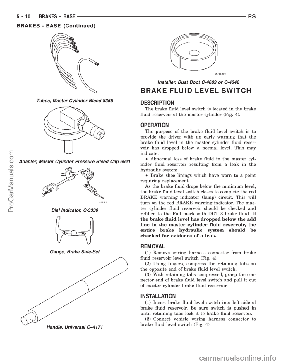
Tubes, Master Cylinder Bleed 8358
Adapter, Master Cylinder Pressure Bleed Cap 6921
Dial Indicator, C-3339
Gauge, Brake Safe-Set
Handle, Universal C±4171
Installer, Dust Boot C-4689 or C-4842
5 - 10 BRAKES - BASERS
BRAKES - BASE (Continued)
ProCarManuals.com
Page 156 of 2399
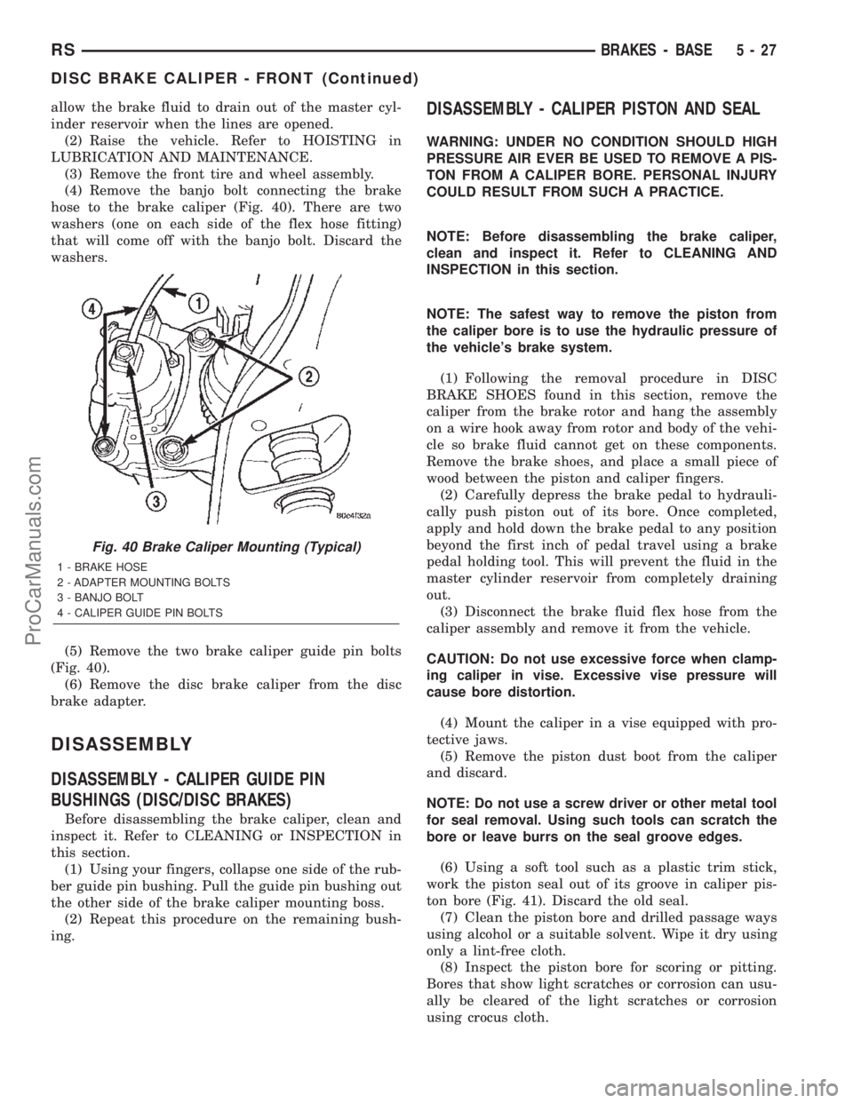
allow the brake fluid to drain out of the master cyl-
inder reservoir when the lines are opened.
(2) Raise the vehicle. Refer to HOISTING in
LUBRICATION AND MAINTENANCE.
(3) Remove the front tire and wheel assembly.
(4) Remove the banjo bolt connecting the brake
hose to the brake caliper (Fig. 40). There are two
washers (one on each side of the flex hose fitting)
that will come off with the banjo bolt. Discard the
washers.
(5) Remove the two brake caliper guide pin bolts
(Fig. 40).
(6) Remove the disc brake caliper from the disc
brake adapter.
DISASSEMBLY
DISASSEMBLY - CALIPER GUIDE PIN
BUSHINGS (DISC/DISC BRAKES)
Before disassembling the brake caliper, clean and
inspect it. Refer to CLEANING or INSPECTION in
this section.
(1) Using your fingers, collapse one side of the rub-
ber guide pin bushing. Pull the guide pin bushing out
the other side of the brake caliper mounting boss.
(2) Repeat this procedure on the remaining bush-
ing.
DISASSEMBLY - CALIPER PISTON AND SEAL
WARNING: UNDER NO CONDITION SHOULD HIGH
PRESSURE AIR EVER BE USED TO REMOVE A PIS-
TON FROM A CALIPER BORE. PERSONAL INJURY
COULD RESULT FROM SUCH A PRACTICE.
NOTE: Before disassembling the brake caliper,
clean and inspect it. Refer to CLEANING AND
INSPECTION in this section.
NOTE: The safest way to remove the piston from
the caliper bore is to use the hydraulic pressure of
the vehicle's brake system.
(1) Following the removal procedure in DISC
BRAKE SHOES found in this section, remove the
caliper from the brake rotor and hang the assembly
on a wire hook away from rotor and body of the vehi-
cle so brake fluid cannot get on these components.
Remove the brake shoes, and place a small piece of
wood between the piston and caliper fingers.
(2) Carefully depress the brake pedal to hydrauli-
cally push piston out of its bore. Once completed,
apply and hold down the brake pedal to any position
beyond the first inch of pedal travel using a brake
pedal holding tool. This will prevent the fluid in the
master cylinder reservoir from completely draining
out.
(3) Disconnect the brake fluid flex hose from the
caliper assembly and remove it from the vehicle.
CAUTION: Do not use excessive force when clamp-
ing caliper in vise. Excessive vise pressure will
cause bore distortion.
(4) Mount the caliper in a vise equipped with pro-
tective jaws.
(5) Remove the piston dust boot from the caliper
and discard.
NOTE: Do not use a screw driver or other metal tool
for seal removal. Using such tools can scratch the
bore or leave burrs on the seal groove edges.
(6) Using a soft tool such as a plastic trim stick,
work the piston seal out of its groove in caliper pis-
ton bore (Fig. 41). Discard the old seal.
(7) Clean the piston bore and drilled passage ways
using alcohol or a suitable solvent. Wipe it dry using
only a lint-free cloth.
(8) Inspect the piston bore for scoring or pitting.
Bores that show light scratches or corrosion can usu-
ally be cleared of the light scratches or corrosion
using crocus cloth.
Fig. 40 Brake Caliper Mounting (Typical)
1 - BRAKE HOSE
2 - ADAPTER MOUNTING BOLTS
3 - BANJO BOLT
4 - CALIPER GUIDE PIN BOLTS
RSBRAKES - BASE5-27
DISC BRAKE CALIPER - FRONT (Continued)
ProCarManuals.com
Page 167 of 2399
CAUTION: Do not hone the bore of the cylinder as
this will remove the anodized surface from the bore.
DESCRIPTION - RHD
The master cylinder used on right hand drive
(RHD) vehicles functions similarly to that used on
left hand drive (LHD) vehicles. The RHD master cyl-
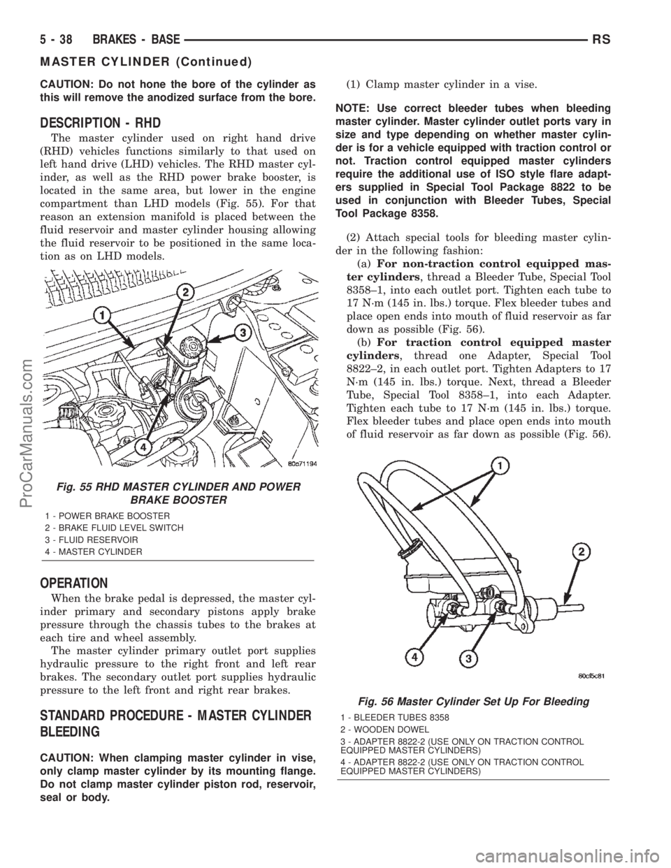
inder, as well as the RHD power brake booster, is
located in the same area, but lower in the engine
compartment than LHD models (Fig. 55). For that
reason an extension manifold is placed between the
fluid reservoir and master cylinder housing allowing
the fluid reservoir to be positioned in the same loca-
tion as on LHD models.
OPERATION
When the brake pedal is depressed, the master cyl-
inder primary and secondary pistons apply brake
pressure through the chassis tubes to the brakes at
each tire and wheel assembly.
The master cylinder primary outlet port supplies
hydraulic pressure to the right front and left rear
brakes. The secondary outlet port supplies hydraulic
pressure to the left front and right rear brakes.
STANDARD PROCEDURE - MASTER CYLINDER
BLEEDING
CAUTION: When clamping master cylinder in vise,
only clamp master cylinder by its mounting flange.
Do not clamp master cylinder piston rod, reservoir,
seal or body.(1) Clamp master cylinder in a vise.
NOTE: Use correct bleeder tubes when bleeding
master cylinder. Master cylinder outlet ports vary in
size and type depending on whether master cylin-
der is for a vehicle equipped with traction control or
not. Traction control equipped master cylinders
require the additional use of ISO style flare adapt-
ers supplied in Special Tool Package 8822 to be
used in conjunction with Bleeder Tubes, Special
Tool Package 8358.
(2) Attach special tools for bleeding master cylin-
der in the following fashion:
(a)For non-traction control equipped mas-
ter cylinders, thread a Bleeder Tube, Special Tool
8358±1, into each outlet port. Tighten each tube to
17 N´m (145 in. lbs.) torque. Flex bleeder tubes and
place open ends into mouth of fluid reservoir as far
down as possible (Fig. 56).
(b)For traction control equipped master
cylinders, thread one Adapter, Special Tool
8822±2, in each outlet port. Tighten Adapters to 17
N´m (145 in. lbs.) torque. Next, thread a Bleeder
Tube, Special Tool 8358±1, into each Adapter.
Tighten each tube to 17 N´m (145 in. lbs.) torque.
Flex bleeder tubes and place open ends into mouth
of fluid reservoir as far down as possible (Fig. 56).
Fig. 55 RHD MASTER CYLINDER AND POWER
BRAKE BOOSTER
1 - POWER BRAKE BOOSTER
2 - BRAKE FLUID LEVEL SWITCH
3 - FLUID RESERVOIR
4 - MASTER CYLINDER
Fig. 56 Master Cylinder Set Up For Bleeding
1 - BLEEDER TUBES 8358
2 - WOODEN DOWEL
3 - ADAPTER 8822-2 (USE ONLY ON TRACTION CONTROL
EQUIPPED MASTER CYLINDERS)
4 - ADAPTER 8822-2 (USE ONLY ON TRACTION CONTROL
EQUIPPED MASTER CYLINDERS)
5 - 38 BRAKES - BASERS
MASTER CYLINDER (Continued)
ProCarManuals.com