instrument panel CHRYSLER CARAVAN 2002 Service Manual
[x] Cancel search | Manufacturer: CHRYSLER, Model Year: 2002, Model line: CARAVAN, Model: CHRYSLER CARAVAN 2002Pages: 2399, PDF Size: 57.96 MB
Page 1809 of 2399

(7) Remove instrument panel lower silencer (Fig.
215).
(8) Remove knee bolster (Fig. 216).(9) Disconnect gear shift cable from gear shift
lever (Fig. 217).
(10) Remove gear shift cable from column bracket
(Fig. 217).
(11) Disengage grommet from dash panel (Fig.
218) and remove gear shift cable from inside vehicle.
Fig. 215 Instrument Panel Lower Silencer
1 - INSTRUMENT PANEL LOWER SILENCER
Fig. 216 Knee Bolster
1 - KNEE BOLSTER
Fig. 217 Gearshift Cable at Column
1 - GEAR SHIFT CABLE
Fig. 218 Gearshift Cable/Grommet at Dash Panel
1 - CABLE GROMMET
2 - DASH PANEL
21 - 252 41TE AUTOMATIC TRANSAXLERS
GEAR SHIFT CABLE (Continued)
ProCarManuals.com
Page 1810 of 2399

INSTALLATION
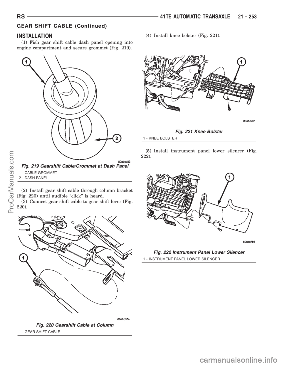
(1) Fish gear shift cable dash panel opening into
engine compartment and secure grommet (Fig. 219).
(2) Install gear shift cable through column bracket
(Fig. 220) until audible ªclickº is heard.
(3) Connect gear shift cable to gear shift lever (Fig.
220).(4) Install knee bolster (Fig. 221).
(5) Install instrument panel lower silencer (Fig.
222).
Fig. 219 Gearshift Cable/Grommet at Dash Panel
1 - CABLE GROMMET
2 - DASH PANEL
Fig. 220 Gearshift Cable at Column
1 - GEAR SHIFT CABLE
Fig. 221 Knee Bolster
1 - KNEE BOLSTER
Fig. 222 Instrument Panel Lower Silencer
1 - INSTRUMENT PANEL LOWER SILENCER
RS41TE AUTOMATIC TRANSAXLE21 - 253
GEAR SHIFT CABLE (Continued)
ProCarManuals.com
Page 1834 of 2399

A conventional mechanical interlock system is also
used. This system manually prohibits shifter move-
ment when the ignition switch is in the LOCK or
ACC positions. Solenoid operation is not required in
these key positions.
For intended BTSI system operation, refer to the
following chart:
ACTION EXPECTED RESPONSE
1. Turn key to the9OFF9
position.1. Shifter CAN be shifted
out of park with brake
pedal applied.
2. Turn key to the
9ON/RUN9position.2. Shifter CANNOT be
shifted out of park.
3. Turn key to the
9ON/RUN9position and
depress the brake pedal.3. Shifter CAN be shifted
out of park.
4. Leave shifter in any
gear and try to return key
to the9LOCK9or9ACC9
position.4. Key cannot be
returned to the9LOCK9or
9ACC9position.
5. Return shifter to
9PARK9and try to remove
the key.5. Key can be removed
(after returning to9LOCK9
position).
6. With the key removed,
try to shift out of9PARK9.6. Shifter cannot be
shifted out of9PARK9.
NOTE: Any failure to meet these expected
responses requires system adjustment or repair.
DIAGNOSIS AND TESTING - BRAKE/
TRANSMISSION SHIFT INTERLOCK SOLENOID
For intended BTSI system operation, refer to the
following chart:
ACTION EXPECTED RESPONSE
1. Turn key to the9OFF9
position.1. Shifter CAN be shifted
out of park with brake
pedal applied.
2. Turn key to the
9ON/RUN9position.2. Shifter CANNOT be
shifted out of park.
3. Turn key to the
9ON/RUN9position and
depress the brake pedal.3. Shifter CAN be shifted
out of park.
4. Leave shifter in any
gear and try to return key
to the9LOCK9or9ACC9
position.4. Key cannot be
returned to the9LOCK9or
9ACC9position.
5. Return shifter to
9PARK9and try to remove
the key.5. Key can be removed
(after returning to9LOCK9
position).
ACTION EXPECTED RESPONSE
6. With the key removed,
try to shift out of9PARK9.6. Shifter cannot be
shifted out of9PARK9.
NOTE: Any failure to meet these expected
responses requires system repair. Refer to the
appropriate Diagnostic Information.
REMOVAL
(1) Disconnect battery negative cable.
(2) Remove instrument panel lower shroud (Fig.
305).
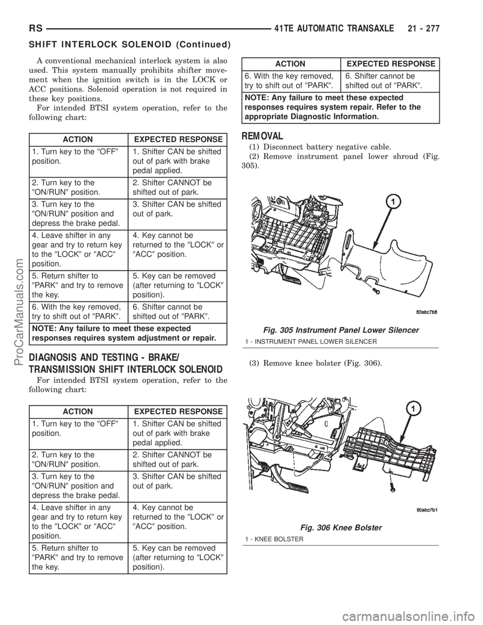
(3) Remove knee bolster (Fig. 306).
Fig. 305 Instrument Panel Lower Silencer
1 - INSTRUMENT PANEL LOWER SILENCER
Fig. 306 Knee Bolster
1 - KNEE BOLSTER
RS41TE AUTOMATIC TRANSAXLE21 - 277
SHIFT INTERLOCK SOLENOID (Continued)
ProCarManuals.com
Page 1836 of 2399

(3) Install steering column lower shroud.
(4) Install knee bolster (Fig. 311).
(5) Install instrument panel lower silencer (Fig.
312).
(6) Connect battery negative cable.
(7) Verify proper shift interlock system operation.
(Refer to 21 - TRANSMISSION/TRANSAXLE/AUTO-
MATIC - 31TH/SHIFT INTERLOCK SOLENOID -
OPERATION)SOLENOID/PRESSURE
SWITCH ASSY
DESCRIPTION
The Solenoid/Pressure Switch Assembly (Fig. 313)
is external to the transaxle and mounted to the
transaxle case. The assembly consists of four sole-
noids that control hydraulic pressure to the LR/CC,
2/4, OD, and UD friction elements. The reverse
clutch is controlled by line pressure from the manual
valve in the valve body. The solenoids are contained
within the Solenoid/Pressure Switch Assembly, and
can only be serviced by replacing the assembly.
The solenoid assembly also contains pressure
switches that monitor and send hydraulic circuit
information to the TCM. Likewise, the pressure
switches can only be service by replacing the assem-
bly.
Fig. 311 Knee Bolster
1 - KNEE BOLSTER
Fig. 312 Instrument Panel Lower Silencer
1 - INSTRUMENT PANEL LOWER SILENCERFig. 313 Solenoid/Pressure Switch Assembly
1 - SOLENOID AND PRESSURE SWITCH ASSEMBLY
RS41TE AUTOMATIC TRANSAXLE21 - 279
SHIFT INTERLOCK SOLENOID (Continued)
ProCarManuals.com
Page 1984 of 2399

BODY
TABLE OF CONTENTS
page page
BODY
DESCRIPTION - VEHICLE IDENTIFICATION....1
WARNING
SAFETY PRECAUTIONS AND WARNINGS . . . 1
DIAGNOSIS AND TESTING
DIAGNOSIS AND TESTING - WATER LEAKS . 1
DIAGNOSIS AND TESTING - WIND NOISE . . . 2
STANDARD PROCEDURE
STANDARD PROCEDURE - PLASTIC BODY
PANEL REPAIR........................3
STANDARD PROCEDURE - HEAT STAKING . 10
SPECIFICATIONS
TORQUE............................11
BODY LUBRICATION...................12SPECIAL TOOLS
BODY..............................13
DOOR - FRONT.........................14
DOORS - SLIDING.......................24
DECKLID/HATCH/LIFTGATE/TAILGATE.......39
EXTERIOR.............................44
HOOD.................................60
INSTRUMENT PANEL.....................63
INTERIOR..............................72
PAINT.................................83
SEATS................................85
STATIONARY GLASS....................107
WEATHERSTRIP/SEALS..................112
BODY STRUCTURE.....................115
BODY
DESCRIPTION - VEHICLE IDENTIFICATION
Throughout this group, references to the
DaimlerChrysler Corporation vehicle family identifi-
cation code are used when describing a procedure
that is unique to that vehicle. Refer to Introduction
Group of this manual for detailed information on
vehicle identification. If a procedure is common to all
vehicles covered in this manual, no reference will be
made to a vehicle family code.
WARNING
SAFETY PRECAUTIONS AND WARNINGS
WARNING: USE A OSHA APPROVED BREATHING
FILTER WHEN SPRAYING PAINT OR SOLVENTS IN
A CONFINED AREA. PERSONAL INJURY CAN
RESULT.
AVOID PROLONGED SKIN CONTACT WITH PETRO-
LEUM OR ALCOHOL ± BASED CLEANING SOL-
VENTS. PERSONAL INJURY CAN RESULT.
DO NOT STAND UNDER A HOISTED VEHICLE THAT
IS NOT PROPERLY SUPPORTED ON SAFETY
STANDS. PERSONAL INJURY CAN RESULT.
CAUTION: When holes must be drilled or punched
in an inner body panel, verify depth of space to the
outer body panel, electrical wiring, or other compo-
nents. Damage to vehicle can result.
Do not weld exterior panels unless combustiblematerial on the interior of vehicle is removed from
the repair area. Fire or hazardous conditions, can
result.
Always have a fire extinguisher ready for use when
welding.
Disconnect the negative (-) cable clamp from the
battery when servicing electrical components that
are live when the ignition is OFF. Damage to electri-
cal system can result.
Do not use abrasive chemicals or compounds on
painted surfaces. Damage to finish can result.
Do not use harsh alkaline based cleaning solvents
on painted or upholstered surfaces. Damage to fin-
ish or color can result.
Do not hammer or pound on plastic trim panel
when servicing interior trim. Plastic panels can
break.
DIAGNOSIS AND TESTING
DIAGNOSIS AND TESTING - WATER LEAKS
Water leaks can be caused by poor sealing,
improper body component alignment, body seam
porosity, missing plugs, or blocked drain holes. Cen-
trifugal and gravitational force can cause water to
drip from a location away from the actual leak point,
making leak detection difficult. All body sealing
points should be water tight in normal wet-driving
conditions. Water flowing downward from the front of
the vehicle should not enter the passenger or luggage
compartment. Moving sealing surfaces will not
always seal water tight under all conditions. At
times, side glass or door seals will allow water to
RSBODY23-1
ProCarManuals.com
Page 1987 of 2399

RIGID, SEMI-RIGID, AND FLEXIBLE PLASTIC PARTS TYPES
CODE FAMILY NAME COMMON TRADE NAME TYPICAL APPLICATION
ASA ACRYLONITRILE STYRENE
ACRYLITELURAN S CONSOLES, GRILLES
ABS ACRYLONITRILE
BUTADIENE STYRENETERLURAN9A9PILLARS, CONSOLES,
GRILLES
ABS/PC ABS/PC ALLOY PULSE, PROLOY,
BAYBLENDDOORS, INSTRUMENT
PANELS
ABS/PVC ABS/PV ALLOY PROLOY, PULSE, LUSTRAN,
CYCLOVINDOOR PANELS, GRILLES,
TRIM
BMC BULK MOLDING
COMPOUNDBMC FENDER EXTENSIONS
EMA EHTYLENE METHYL
ACRYLATE/IONOMERSURLYN, EMA, IONOMER BUMPER GUARDS, PADS
METTON METTON METTON GRILLES, KICK PANELS,
RUNNING BOARDS
MPPO MODIFIED
POLYPHENYLENE OXIDEMPPO SPOILER ASSEMBLY
PA POLYAMID ZYTEL, VYDYNE, PA,
MINLONFENDERS, QUARTER PANELS
PET THERMOPLASTIC
POLYESTERRYNITE TRIM
PBT/PPO PBT/PPO ALLOY GERMAX CLADDINGS
PBTP POLYBUTYLENE
THEREPTHALATEPBT, PBTP, POCAN, VALOX WHEEL COVERS, FENDERS,
GRILLES
PBTP/EEBC POLYBUTYLENE
THEREPTHALATE/EEBC
ALLOYBEXLOY,9M9, PBTP/EEBC FASCIAS, ROCKER PANEL,
MOLDINGS
PC POLYCARBONATE LEXAN, MERLON, CALIBRE,
MAKROLON PCTAIL LIGHT LENSES, IP TRIM,
VALANCE PANELS
PC/ABS PC/ABS ALLOY GERMAX, BAY BLENDS,
PULSEDOORS, INSTRUMENT
PANELS
PPO POLYPHENYLENE OXIDE AZDEL, HOSTALEN,
MARLEX, PRFAX, NORYL,
GTX, PPOINTERIOR TRIM, DOOR
PANELS, SPLASH SHIELDS,
STEERING COLUMN SHROUD
PPO/PA POLYPHENYLENE/
POLYAMIDPPO/PA, GTX 910 FENDERS, QUARTER PANELS
PR/FV FIBERGLASS REINFORCED
PLASTICFIBERGLASS, FV, PR/FV BODY PANELS
PS POLYSTYRENE LUSTREX, STYRON, PS DOOR PANELS, DASH
PANELS
RTM RESIN TRANSFER
MOLDING COMPOUNDRTM BODY PANELS
SMC SHEET MOLDED
COMPOUNDSMC BODY PANELS
TMC TRANSFER MOLDING
COMPOUNDTMC GRILLES
23 - 4 BODYRS
BODY (Continued)
ProCarManuals.com
Page 2044 of 2399

INSTALLATION
(1) Place hood in position on vehicle. With assis-
tance from a helper at the opposite side of the vehicle
to support the hood, install bottom bolts attaching
hood to hinge finger tight.
(2) Install top bolts attaching hood to hinge finger
tight.
(3) Position bolts at marks and tighten. Tighten
bolts to 13.5 N´m (120 in. lbs.) torque. The hood
should be aligned to 4 mm (0.160 in.) gap to the front
fenders and flush across the top surfaces along fend-
ers.
(4) Verify hood operation and alignment.
LATCH
REMOVAL
(1) Release hood latch and open hood.
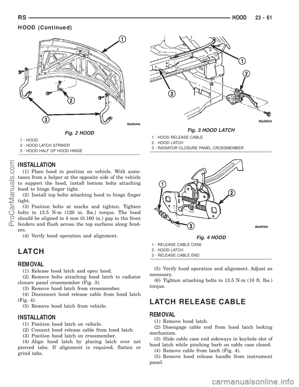
(2) Remove bolts attaching hood latch to radiator
closure panel crossmember (Fig. 3).
(3) Remove hood latch from crossmember.
(4) Disconnect hood release cable from hood latch
(Fig. 4).
(5) Remove hood latch from vehicle.
INSTALLATION
(1) Position hood latch on vehicle.
(2) Connect hood release cable from hood latch.
(3) Position hood latch on crossmember.
(4) Align hood latch by placing latch over net
pierced tabs. If alignment is required, flatten or
grind tabs.(5) Verify hood operation and alignment. Adjust as
necessary.
(6) Tighten attaching bolts to 13.5 N´m (10 ft. lbs.)
torque.
LATCH RELEASE CABLE
REMOVAL
(1) Remove hood latch.
(2) Disengage cable end from hood latch locking
mechanism.
(3) Slide cable case end sideways in keyhole slot of
hood latch while pinching barb on cable case closed.
(4) Remove cable from latch (Fig. 4).
(5) Remove hood release handle from instrument
panel.
Fig. 2 HOOD
1 - HOOD
2 - HOOD LATCH STRIKER
3 - HOOD HALF OF HOOD HINGE
Fig. 3 HOOD LATCH
1 - HOOD RELEASE CABLE
2 - HOOD LATCH
3 - RADIATOR CLOSURE PANEL CROSSMEMBER
Fig. 4 HOOD
1 - RELEASE CABLE CASE
2 - HOOD LATCH
3 - RELEASE CABLE END
RSHOOD23-61
HOOD (Continued)
ProCarManuals.com
Page 2045 of 2399

(6) Disengage rubber grommet cable insulator
from hole in dash panel.
(7) Attach a suitable length of mechanic's wire to
latch end of cable to assist cable installation.
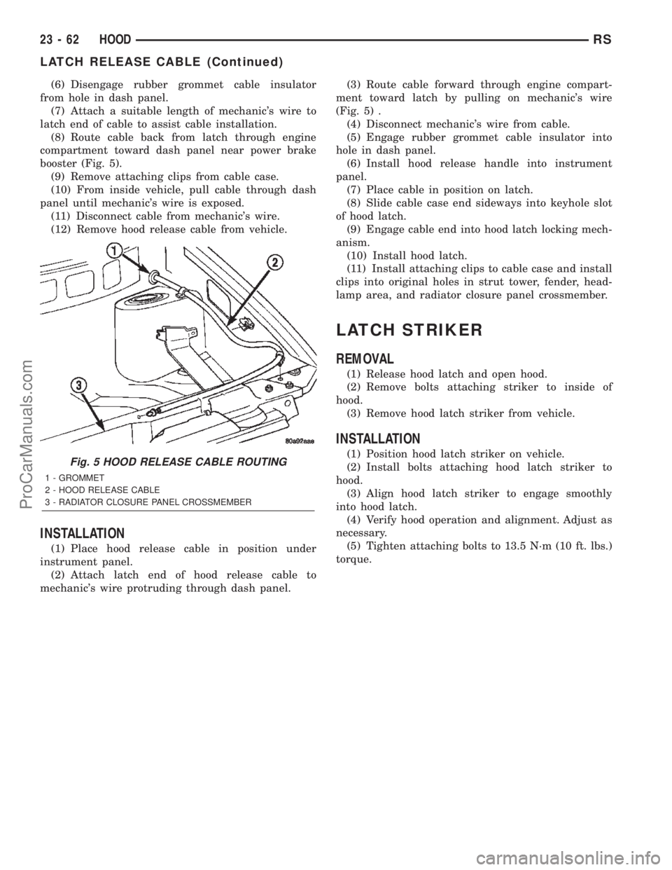
(8) Route cable back from latch through engine
compartment toward dash panel near power brake
booster (Fig. 5).
(9) Remove attaching clips from cable case.
(10) From inside vehicle, pull cable through dash
panel until mechanic's wire is exposed.
(11) Disconnect cable from mechanic's wire.
(12) Remove hood release cable from vehicle.
INSTALLATION
(1) Place hood release cable in position under
instrument panel.
(2) Attach latch end of hood release cable to
mechanic's wire protruding through dash panel.(3) Route cable forward through engine compart-
ment toward latch by pulling on mechanic's wire
(Fig. 5) .
(4) Disconnect mechanic's wire from cable.
(5) Engage rubber grommet cable insulator into
hole in dash panel.
(6) Install hood release handle into instrument
panel.
(7) Place cable in position on latch.
(8) Slide cable case end sideways into keyhole slot
of hood latch.
(9) Engage cable end into hood latch locking mech-
anism.
(10) Install hood latch.
(11) Install attaching clips to cable case and install
clips into original holes in strut tower, fender, head-
lamp area, and radiator closure panel crossmember.
LATCH STRIKER
REMOVAL
(1) Release hood latch and open hood.
(2) Remove bolts attaching striker to inside of
hood.
(3) Remove hood latch striker from vehicle.
INSTALLATION
(1) Position hood latch striker on vehicle.
(2) Install bolts attaching hood latch striker to
hood.
(3) Align hood latch striker to engage smoothly
into hood latch.
(4) Verify hood operation and alignment. Adjust as
necessary.
(5) Tighten attaching bolts to 13.5 N´m (10 ft. lbs.)
torque.Fig. 5 HOOD RELEASE CABLE ROUTING
1 - GROMMET
2 - HOOD RELEASE CABLE
3 - RADIATOR CLOSURE PANEL CROSSMEMBER
23 - 62 HOODRS
LATCH RELEASE CABLE (Continued)
ProCarManuals.com
Page 2046 of 2399

INSTRUMENT PANEL
TABLE OF CONTENTS
page page
CLUSTER BEZEL
REMOVAL.............................63
INSTALLATION.........................63
CUP HOLDER
REMOVAL.............................64
INSTALLATION.........................64
GLOVE BOX
REMOVAL.............................64
INSTALLATION.........................64
GLOVE BOX LATCH
REMOVAL.............................64
INSTALLATION.........................64
GLOVE BOX LATCH STRIKER
REMOVAL.............................64
INSTALLATION.........................65
INSTRUMENT PANEL ASSEMBLY
REMOVAL.............................65
INSTALLATION.........................67
INSTRUMENT PANEL CENTER BEZEL
REMOVAL.............................68
INSTALLATION.........................68INSTRUMENT PANEL END CAP
REMOVAL.............................68
INSTALLATION.........................68
INSTRUMENT PANEL TOP COVER
REMOVAL.............................69
INSTALLATION.........................69
LOWER CONSOLE
REMOVAL.............................69
INSTALLATION.........................69
LOWER INSTRUMENT PANEL
REMOVAL.............................70
INSTALLATION.........................70
LOWER STEERING COLUMN COVER
REMOVAL.............................70
INSTALLATION.........................70
STEERING COLUMN COVER BACKING PLATE
REMOVAL.............................70
INSTALLATION.........................71
OVER STEERING COLUMN COVER
REMOVAL.............................71
INSTALLATION.........................71
CLUSTER BEZEL
REMOVAL
(1) Disconnect and isolate the battery negative
cable.
(2) Remove Over Steering Column Bezel by lifting
it straight up with a firm pull.
(3) Remove the four bezel attaching screws (Fig.
1).
(4) Tilt the steering column in the full down posi-
tion.
(5) Pull rearward on the cluster bezel and remove.
INSTALLATION
(1) Maneuver cluster bezel over steering column
and into position (Fig. 1).
(2) Install the four bezel attaching screws.
(3) Install the Over Steering Column Bezel by
positioning it over the retaining slots and firmly
snapping it into place.
(4) Connect the battery negative cable.
Fig. 1 CLUSTER BEZEL
1 - INSTRUMENT PANEL
2 - CLUSTER BEZEL
RSINSTRUMENT PANEL23-63
ProCarManuals.com
Page 2047 of 2399

CUP HOLDER
REMOVAL
(1) Remove the screw access cover from the bottom
of the center bezel.
(2) Remove the center bezel attaching screws.
(3) Using a trim stick (special tool #C-4755) or
equivalent, gently pry out on the edge of the instru-
ment panel center bezel. Hang off to the side leaving
the accessory switches connected.
(4) Pull the cup holder assembly rearward to dis-
engage the rear guide studs from instrument panel
(Fig. 2).
INSTALLATION
(1) Ensure the cup holder assembly is in the closed
position. The cup holder assembly must be installed
as an assembly to ensure proper track position.
(2) Place the cup holder assembly into position in
the lower instrument panel and slide into opening
until the rear guide struts snap into place (Fig. 2).
(3) Install the center bezel.
(4) Install the center bezel attaching screws
(5) Install the cup holder. Align the cup holder
assembly with the track and firmly slide shut to
engage retaining tang.
(6) Install the screw access cover to the bottom of
the center bezel.
GLOVE BOX
REMOVAL
(1) Open glove box.
(2) Push in on sides of glove box bin and lower
door.
(3) Pivot glove box downward and disengage hinge
hooks from instrument panel.
(4) Remove glove box.
INSTALLATION
(1) Place glove box in position.
(2) Engage hinge hooks into instrument panel and
pivot glove box upward.
(3) Push in sides of glove box bin and snap glove
box assembly into instrument panel.
(4) Close glove box door.
GLOVE BOX LATCH
REMOVAL
(1) Open glove box.
(2) Push in on sides of glove box bin and lower
door.
(3) Pivot glove box downward and disengage hinge
hooks from instrument panel.
(4) Remove glove box.
(5) Remove the assembly screws.
(6) Disassemble the glove box.
(7) Separate the latch from the glove box assembly.
INSTALLATION
(1) Install the latch onto the glove box assembly.
(2) Assemble the glove box.
(3) Install the assembly screws.
(4) Engage hinge hooks into instrument panel and
pivot glove box upward.
(5) Push in sides of glove box bin and snap glove
box assembly into instrument panel.
(6) Close glove box door.
GLOVE BOX LATCH STRIKER
REMOVAL
(1) Open glove box door.
(2) Remove screws holding lock striker to instru-
ment panel.
(3) Remove glove box latch striker.
Fig. 2 CUP HOLDER
1 - LOWER INSTRUMENT PANEL
2 - CUPHOLDER AND TRACK
23 - 64 INSTRUMENT PANELRS
ProCarManuals.com