fig. 78 CHRYSLER CARAVAN 2002 Service Manual
[x] Cancel search | Manufacturer: CHRYSLER, Model Year: 2002, Model line: CARAVAN, Model: CHRYSLER CARAVAN 2002Pages: 2399, PDF Size: 57.96 MB
Page 2329 of 2399
(1) Recover the refrigerant from the refrigerant
system. (Refer to 24 - HEATING & AIR CONDI-
TIONING/PLUMBING - FRONT/REFRIGERANT -
STANDARD PROCEDURE - REFRIGERANT
RECOVERY).
(2) Remove the air cleaner housing from the right
side of the engine compartment.
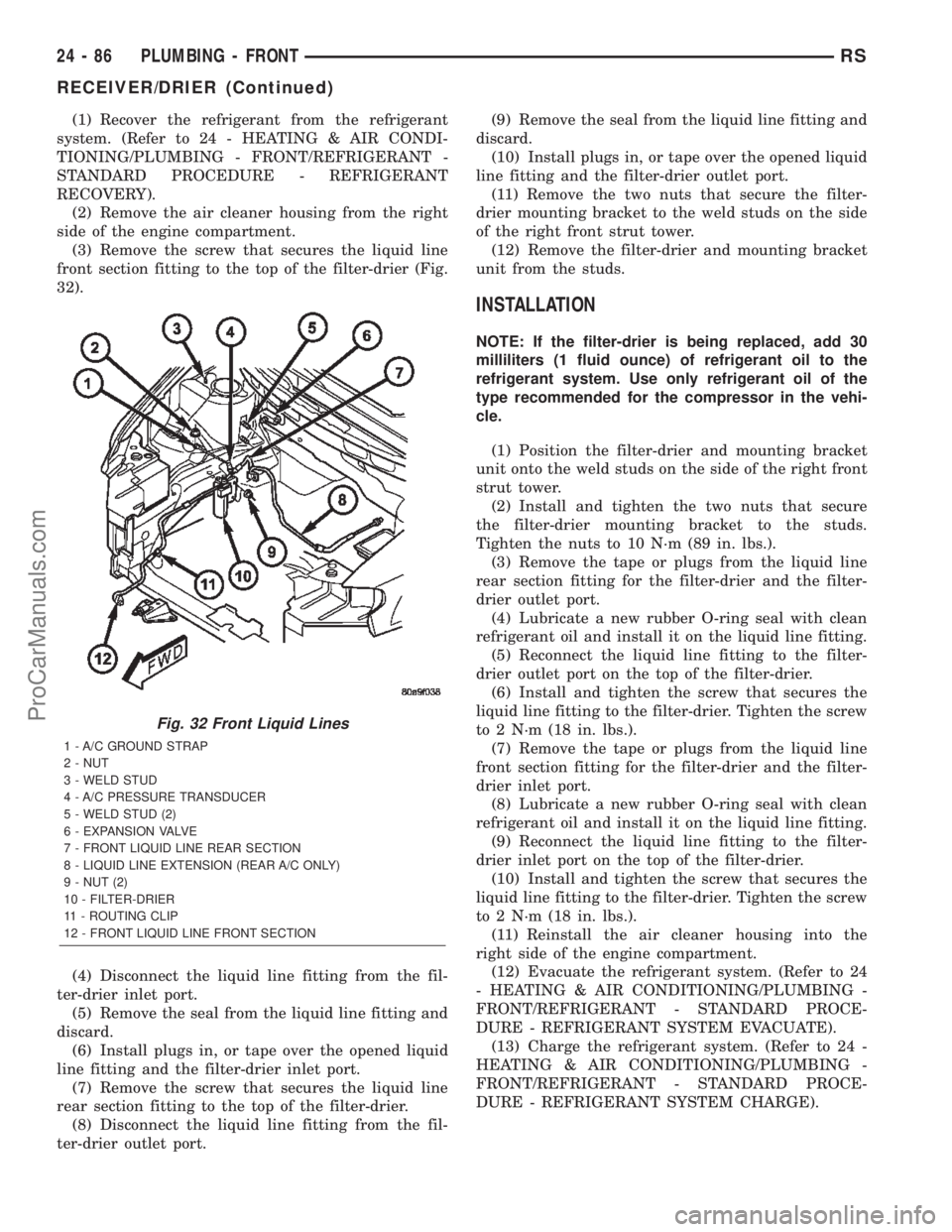
(3) Remove the screw that secures the liquid line
front section fitting to the top of the filter-drier (Fig.
32).
(4) Disconnect the liquid line fitting from the fil-
ter-drier inlet port.
(5) Remove the seal from the liquid line fitting and
discard.
(6) Install plugs in, or tape over the opened liquid
line fitting and the filter-drier inlet port.
(7) Remove the screw that secures the liquid line
rear section fitting to the top of the filter-drier.
(8) Disconnect the liquid line fitting from the fil-
ter-drier outlet port.(9) Remove the seal from the liquid line fitting and
discard.
(10) Install plugs in, or tape over the opened liquid
line fitting and the filter-drier outlet port.
(11) Remove the two nuts that secure the filter-
drier mounting bracket to the weld studs on the side
of the right front strut tower.
(12) Remove the filter-drier and mounting bracket
unit from the studs.
INSTALLATION
NOTE: If the filter-drier is being replaced, add 30
milliliters (1 fluid ounce) of refrigerant oil to the
refrigerant system. Use only refrigerant oil of the
type recommended for the compressor in the vehi-
cle.
(1) Position the filter-drier and mounting bracket
unit onto the weld studs on the side of the right front
strut tower.
(2) Install and tighten the two nuts that secure
the filter-drier mounting bracket to the studs.
Tighten the nuts to 10 N´m (89 in. lbs.).
(3) Remove the tape or plugs from the liquid line
rear section fitting for the filter-drier and the filter-
drier outlet port.
(4) Lubricate a new rubber O-ring seal with clean
refrigerant oil and install it on the liquid line fitting.
(5) Reconnect the liquid line fitting to the filter-
drier outlet port on the top of the filter-drier.
(6) Install and tighten the screw that secures the
liquid line fitting to the filter-drier. Tighten the screw
to 2 N´m (18 in. lbs.).
(7) Remove the tape or plugs from the liquid line
front section fitting for the filter-drier and the filter-
drier inlet port.
(8) Lubricate a new rubber O-ring seal with clean
refrigerant oil and install it on the liquid line fitting.
(9) Reconnect the liquid line fitting to the filter-
drier inlet port on the top of the filter-drier.
(10) Install and tighten the screw that secures the
liquid line fitting to the filter-drier. Tighten the screw
to 2 N´m (18 in. lbs.).
(11) Reinstall the air cleaner housing into the
right side of the engine compartment.
(12) Evacuate the refrigerant system. (Refer to 24
- HEATING & AIR CONDITIONING/PLUMBING -
FRONT/REFRIGERANT - STANDARD PROCE-
DURE - REFRIGERANT SYSTEM EVACUATE).
(13) Charge the refrigerant system. (Refer to 24 -
HEATING & AIR CONDITIONING/PLUMBING -
FRONT/REFRIGERANT - STANDARD PROCE-
DURE - REFRIGERANT SYSTEM CHARGE).
Fig. 32 Front Liquid Lines
1 - A/C GROUND STRAP
2 - NUT
3 - WELD STUD
4 - A/C PRESSURE TRANSDUCER
5 - WELD STUD (2)
6 - EXPANSION VALVE
7 - FRONT LIQUID LINE REAR SECTION
8 - LIQUID LINE EXTENSION (REAR A/C ONLY)
9 - NUT (2)
10 - FILTER-DRIER
11 - ROUTING CLIP
12 - FRONT LIQUID LINE FRONT SECTION
24 - 86 PLUMBING - FRONTRS
RECEIVER/DRIER (Continued)
ProCarManuals.com
Page 2330 of 2399

REFRIGERANT
DESCRIPTION
The refrigerant used in this air conditioning sys-
tem is a HydroFluoroCarbon (HFC), type R-134a.
Unlike R-12, which is a ChloroFluoroCarbon (CFC),
R-134a refrigerant does not contain ozone-depleting
chlorine. R-134a refrigerant is a non-toxic, non-flam-
mable, clear, and colorless liquefied gas. Even though
R-134a does not contain chlorine, it must be
reclaimed and recycled just like CFC-type refriger-
ants. This is because R-134a is a greenhouse gas and
can contribute to global warming.
OPERATION
R-134a refrigerant is not compatible with R-12
refrigerant in an air conditioning system. Even a
small amount of R-12 added to an R-134a refrigerant
system will cause compressor failure, refrigerant oil
sludge or poor air conditioning system performance.
In addition, the PolyAlkylene Glycol (PAG) synthetic
refrigerant oils used in an R-134a refrigerant system
are not compatible with the mineral-based refriger-
ant oils used in an R-12 refrigerant system. R-134a
refrigerant system service ports, service tool couplers
and refrigerant dispensing bottles have all been
designed with unique fittings to ensure that an
R-134a system is not accidentally contaminated with
the wrong refrigerant (R-12). There are also labels
posted in the engine compartment of the vehicle and
on the compressor identifying to service technicians
that the air conditioning system is equipped with
R-134a.
DIAGNOSIS AND TESTING
DIAGNOSIS AND TESTING - REFRIGERANT
SYSTEM CHARGE LEVEL
WARNING: REFER TO THE APPLICABLE WARN-
INGS AND CAUTIONS FOR THIS SYSTEM BEFORE
PERFORMING THE FOLLOWING OPERATION.
(Refer to 24 - HEATING & AIR CONDITIONING/
PLUMBING - FRONT - WARNING - A/C PLUMBING)
and (Refer to 24 - HEATING & AIR CONDITIONING/
PLUMBING - FRONT - CAUTION - A/C PLUMBING).
NOTE: The proper amount of R-134a refrigerant for
the refrigerant system in this model is:
²Single or Dual Zone (Front Unit Only) - 0.96
kilograms (2.13 pounds or 34 ounces)
²Three Zone (Front and Rear Units) - 1.31 kilo-
grams (2.88 pounds or 46 ounces)The procedure that follows should be used to deter-
mine whether the refrigerant system contains the
proper refrigerant charge. Symptoms of an improper
refrigerant charge (low) include: poor air conditioner
performance, fog emitted from the air conditioner
outlets, a hissing sound from the expansion valve/
evaporator area. There are two different methods
with which the refrigerant charge level may be
tested:
²Using a DRBIIItscan tool, a thermocouple and
the Charge Determination Chart (Fig. 33). Refer to
the appropriate diagnostic information.
²Using a manifold gauge set, a thermocouple and
the Charge Determination Chart (Fig. 33).
A temperature probe is required to measure liquid
line temperature. The clamp-on, Type K thermocou-
ple temperature probe used in this procedure is
available through the DaimlerChrysler Professional
Service Equipment (PSE) program. This probe (PSE
#66-324-0014 or #80PK-1A) is compatible with tem-
perature-measuring instruments that accept Type K
thermocouples, and have a miniature connector
input. Other temperature probes are available
through aftermarket sources; however, all references
in this procedure will reflect the use of the probe
made available through the PSE program.
In order to use the temperature probe, a digital
thermometer will also be required. If a digital ther-
mometer is not available, an adapter is available
through the PSE program that will convert any stan-
dard digital multimeter into a digital thermometer.
This adapter is designed to accept any standard Type
K thermocouple. If a digital multimeter is not avail-
able, this tool is also available through the PSE pro-
gram.
NOTE: When connecting the service equipment
couplings to the refrigerant system service ports,
be certain that the valve of each coupling is fully
closed. This will reduce the amount of effort
required to make the connection.
(1) Remove the caps from the refrigerant system
service ports and attach a manifold gauge set or a
R-134a refrigerant recovery/recycling/charging sta-
tion that meets SAE Standard J2210 to the refriger-
ant system.
(2) Attach a clamp-on thermocouple to the liquid
line. The thermocouple must be placed as close to the
A/C pressure transducer as possible to accurately
observe liquid line temperature.
(3) Bring the refrigerant system up to operating
temperature and pressure. This is done by allowing
the engine to run at idle under the following condi-
tions for five minutes.
(a) Front windows are open.
(b) Transaxle in Park.
RSPLUMBING - FRONT24-87
ProCarManuals.com
Page 2331 of 2399

(c) Front heater-A/C controls set to outside air,
full cool, panel mode, blower high, and compressor
engaged.
(d) If the vehicle is so equipped, the rear heater-
A/C controls must be set to full cool and blower
high.
(4) Raise the liquid line (discharge) pressure to
about 1793 kPa (260 psi) by placing a piece of card-
board over part of the front side of the condenser. To
place the cardboard properly, remove the upper radi-
ator sight shield from the front fascia. Cover only
enough of the condenser to raise and maintain the
liquid line pressure at the specified level.
(5) Observe the liquid line (discharge) pressure
and liquid line temperature. Using the Charge Deter-
mination Chart (Fig. 33), determine whether the
refrigerant system is operating within the Proper
Charge Range.
(a) If the refrigerant system is operating in the
Undercharged area of the chart, add 0.057 kilo-
gram (0.125 pound or 2 ounces) of refrigerant to
the system.
(b) If the refrigerant system is operating in the
Overcharged area of the chart, reclaim 0.057 kilo-
gram (0.125 pound or 2 ounces) of refrigerant from
the system.(6) Recheck the system charge level following each
refrigerant adjustment. Continue this process until
the system readings are in the Proper Charge Range
area on the Charge Determination Chart.
DIAGNOSIS AND TESTING - REFRIGERANT
SYSTEM LEAKS
WARNING: REFER TO THE APPLICABLE WARN-
INGS AND CAUTIONS FOR THIS SYSTEM BEFORE
PERFORMING THE FOLLOWING OPERATION.
(Refer to 24 - HEATING & AIR CONDITIONING/
PLUMBING - FRONT - WARNING - A/C PLUMBING)
and (Refer to 24 - HEATING & AIR CONDITIONING/
PLUMBING - FRONT - CAUTION - A/C PLUMBING).
If the air conditioning system is not cooling prop-
erly, determine if the refrigerant system is fully-
charged. (Refer to 24 - HEATING & AIR
CONDITIONING/PLUMBING - FRONT/REFRIGER-
ANT - DIAGNOSIS AND TESTING - REFRIGER-
ANT SYSTEM CHARGE LEVEL).
If the refrigerant system is low or empty; a leak at
a refrigerant line, connector fitting, component, or
component seal is likely. While an oily residue on or
near refrigerant system lines, connector fittings, com-
ponents, or component seals can indicate the general
Fig. 33 Charge Determination Chart, Ambient Test Condition 85ÉF
24 - 88 PLUMBING - FRONTRS
REFRIGERANT (Continued)
ProCarManuals.com
Page 2332 of 2399

location of a possible refrigerant leak, the exact leak
location should be confirmed with an electronic leak
detector prior to component repair or replacement.
An electronic leak detector designed for R-134a
refrigerant is recommended for locating and confirm-
ing refrigerant system leaks. See the operating
instructions supplied by the equipment manufacturer
for proper care and use of this equipment.
To detect a leak in the refrigerant system, perform
one of the following procedures as indicated by the
results of the refrigerant system charge level test.
SYSTEM EMPTY
(1) Evacuate the refrigerant system. (Refer to 24 -
HEATING & AIR CONDITIONING/PLUMBING -
FRONT/REFRIGERANT - STANDARD PROCE-
DURE - REFRIGERANT SYSTEM EVACUATE).
(2) Connect and dispense 0.283 kilograms (0.625
pounds or 10 ounces) of R-134a refrigerant into the
evacuated refrigerant system. (Refer to 24 - HEAT-
ING & AIR CONDITIONING/PLUMBING - FRONT/
REFRIGERANT - STANDARD PROCEDURE -
REFRIGERANT SYSTEM CHARGE).
(3) Proceed to the SYSTEM LOW procedures.
SYSTEM LOW
(1) Position the vehicle in a wind-free work area.
This will aid in detecting small leaks.
(2) Bring the refrigerant system up to operating
temperature and pressure. This is done by allowing
the engine to run at idle under the following condi-
tions for five minutes, then turning the engine off.
(a) Front windows are open.
(b) Rear air conditioner Off (if equipped).
(c) Transaxle in Park.
(d) Front heater-A/C controls set to outside air,
panel mode, blower high, and compressor engaged.
(3) Wait five to seven minutes and, with the
engine not running, use a electronic R-134a leak
detector and search for leaks. Because R-134a refrig-
erant is heavier than air, the leak detector probe
should be moved slowly along the bottom side of all
refrigerant lines, connector fittings and components.
(4) To inspect an evaporator for leaks, insert the
electronic leak detector probe into a floor outlet or
the recirculation air intake.
DIAGNOSIS AND TESTING - REFRIGERANT
SYSTEM CHARGE LEVEL 2.5L DIESEL
WARNING: REFER TO THE APPLICABLE WARN-
INGS AND CAUTIONS FOR THIS SYSTEM BEFORE
PERFORMING THE FOLLOWING OPERATION.
(Refer to 24 - HEATING & AIR CONDITIONING/
PLUMBING - FRONT - WARNING - A/C PLUMBING)and (Refer to 24 - HEATING & AIR CONDITIONING/
PLUMBING - FRONT - CAUTION - A/C PLUMBING).
NOTE: The proper amount of R-134a refrigerant for
the refrigerant system in this model is:
²Single or Dual Zone (Front Unit Only - 2.5L Die-
sel) ± 0.91 kilograms (2.00 pounds or 32 ounces)
²Single or Dual Zone (Front Unit Only) - 0.96
kilograms (2.13 pounds or 34 ounces)
²Three Zone (Front and Rear Units) - 1.31 kilo-
grams (2.88 pounds or 46 ounces)
The procedure that follows should be used to deter-
mine whether the refrigerant system contains the
proper refrigerant charge. Symptoms of an improper
refrigerant charge (low) include: poor air conditioner
performance, fog emitted from the air conditioner
outlets, a hissing sound from the expansion valve/
evaporator area. There are two different methods
with which the refrigerant charge level may be
tested:
²Using a DRBIIItscan tool, a thermocouple and
the Charge Determination Chart (Fig. 34). Refer to
the appropriate diagnostic information.
²Using a manifold gauge set, a thermocouple and
the Charge Determination Chart (Fig. 34).
A temperature probe is required to measure liquid
line temperature. The clamp-on, Type K thermocou-
ple temperature probe used in this procedure is
available through the DaimlerChrysler Professional
Service Equipment (PSE) program. This probe (PSE
#66-324-0014 or #80PK-1A) is compatible with tem-
perature-measuring instruments that accept Type K
thermocouples, and have a miniature connector
input. Other temperature probes are available
through aftermarket sources; however, all references
in this procedure will reflect the use of the probe
made available through the PSE program.
In order to use the temperature probe, a digital
thermometer will also be required. If a digital ther-
mometer is not available, an adapter is available
through the PSE program that will convert any stan-
dard digital multimeter into a digital thermometer.
This adapter is designed to accept any standard Type
K thermocouple. If a digital multimeter is not avail-
able, this tool is also available through the PSE pro-
gram.
NOTE: When connecting the service equipment
couplings to the refrigerant system service ports,
be certain that the valve of each coupling is fully
closed. This will reduce the amount of effort
required to make the connection.
(1) Remove the caps from the refrigerant system
service ports and attach a manifold gauge set or a
R-134a refrigerant recovery/recycling/charging sta-
RSPLUMBING - FRONT24-89
REFRIGERANT (Continued)
ProCarManuals.com
Page 2333 of 2399

tion that meets SAE Standard J2210 to the refriger-
ant system.
(2) Attach a clamp-on thermocouple to the liquid
line. The thermocouple must be placed as close to the
A/C pressure transducer as possible to accurately
observe liquid line temperature.
(3) Bring the refrigerant system up to operating
temperature and pressure. This is done by allowing
the engine to run at idle under the following condi-
tions for five minutes.
(a) Front windows are open.
(b) Transaxle in Park.
(c) Front heater-A/C controls set to outside air,
full cool, panel mode, blower high, and compressor
engaged.
(d) If the vehicle is so equipped, the rear heater-
A/C controls must be set to full cool and blower
high.
(4) Raise the liquid line (discharge) pressure to
about 1793 kPa (260 psi) by placing a piece of card-
board over part of the front side of the condenser. To
place the cardboard properly, remove the upper radi-
ator sight shield from the front fascia. Cover only
enough of the condenser to raise and maintain the
liquid line pressure at the specified level.
(5) Observe the liquid line (discharge) pressure
and liquid line temperature. Using the Charge Deter-
mination Chart (Fig. 34), determine whether therefrigerant system is operating within the Proper
Charge Range.
(a) If the refrigerant system is operating in the
Undercharged area of the chart, add 0.057 kilo-
gram (0.125 pound or 2 ounces) of refrigerant to
the system.
(b) If the refrigerant system is operating in the
Overcharged area of the chart, reclaim 0.057 kilo-
gram (0.125 pound or 2 ounces) of refrigerant from
the system.
(6) Recheck the system charge level following each
refrigerant adjustment. Continue this process until
the system readings are in the Proper Charge Range
area on the Charge Determination Chart (Fig. 34).
STANDARD PROCEDURE
STANDARD PROCEDURE - REFRIGERANT
SYSTEM SERVICE EQUIPMENT
RECOVERY/RECYCLING STATION
When servicing the air conditioning system, a
R-134a refrigerant recovery/recycling/charging sta-
tion that meets SAE Standard J2210 must be used
(Fig. 35). Contact PSE or an automotive service
equipment supplier for refrigerant recovery/recycling/
charging equipment. See the operating instructions
Fig. 34 Charge Determination Chart, Ambient Test Condition 85ÉF
24 - 90 PLUMBING - FRONTRS
REFRIGERANT (Continued)
ProCarManuals.com
Page 2334 of 2399

supplied by the equipment manufacturer for proper
care and use of this equipment.
MANIFOLD GAUGE SET CONNECTIONSCAUTION: Do not use an R-12 manifold gauge set
on an R-134a system. The refrigerants are not com-
patible and system damage will result.
A manifold gauge set may be needed with some
recovery/recycling/charging equipment (Fig. 36). The
service hoses on the gauge set being used should
have manual (turn wheel), or automatic back-flow
valves at the service port connector ends. This will
prevent refrigerant from being released into the
atmosphere.
²LOW PRESSURE GAUGE HOSE- The low
pressure hose (Blue with Black stripe) attaches to
the suction (low side) service port. This port is
located on the suction line, near the compressor at
the front of the engine compartment.
²HIGH PRESSURE GAUGE HOSE- The high
pressure hose (Red with Black stripe) attaches to the
discharge (high side) service port. This port is located
on the liquid line near the filter-drier at the rear of
the engine compartment.
²RECOVERY/RECYCLING/EVACUATION/
CHARGING HOSE- The center manifold hose (Yel-
low, or White, with Black stripe) is used to recover,
evacuate, and charge the refrigerant system. When
the low or high pressure valves on the manifold
gauge set are opened, the refrigerant in the system
will escape through this hose.
STANDARD PROCEDURE - REFRIGERANT
SYSTEM CHARGE
WARNING: REFER TO THE APPLICABLE WARN-
INGS AND CAUTIONS FOR THIS SYSTEM BEFORE
PERFORMING THE FOLLOWING OPERATION.
(Refer to 24 - HEATING & AIR CONDITIONING/
PLUMBING - FRONT - WARNING - A/C PLUMBING)
and (Refer to 24 - HEATING & AIR CONDITIONING/
PLUMBING - FRONT - CAUTION - A/C PLUMBING).
After all refrigerant system leaks have been
repaired and the refrigerant system has been evacu-
ated, a refrigerant charge can be injected into the
system. For the proper amount of the refrigerant
charge, refer to REFRIGERANT CHARGE CAPAC-
ITY . A R-134a refrigerant recovery/recycling/charg-
ing station that meets SAE Standard J2210 must be
used to charge the refrigerant system with R-134a
refrigerant. See the operating instructions supplied
by the equipment manufacturer for proper care and
use of this equipment.
REFRIGERANT CHARGE CAPACITY
The R-134a refrigerant system charge capacity for
this vehicle is:
Fig. 35 Refrigerant Recovery/Recycling Station -
Typical
1 - R-134 REFRIGERANT RECOVERY MACHINE
Fig. 36 Manifold Gauge Set - Typical
1 - HIGH PRESSURE GAUGE
2 - VALVE
3 - VACUUM/REFRIGERANT HOSE (YELLOW W/BLACK STRIPE)
4 - HIGH PRESSURE HOSE (RED W/BLACK STRIPE)
5 - LOW PRESSURE HOSE (BLUE W/BLACK STRIPE)
6 - VALVE
7 - LOW PRESSURE GAUGE
RSPLUMBING - FRONT24-91
REFRIGERANT (Continued)
ProCarManuals.com
Page 2337 of 2399

SUCTION LINE
REMOVAL
The front air conditioner suction line includes the
low side service port on a section of tubing located
near the compressor. On models equipped with the
optional rear air conditioner, the front air conditioner
suction line also includes a suction line hose and
tube extension that connects the front suction line to
the suction line for the rear air conditioner.
WARNING: REFER TO THE APPLICABLE WARN-
INGS AND CAUTIONS FOR THIS SYSTEM BEFORE
PERFORMING THE FOLLOWING OPERATION.
(Refer to 24 - HEATING & AIR CONDITIONING/
PLUMBING - FRONT - WARNING - A/C PLUMBING)
and (Refer to 24 - HEATING & AIR CONDITIONING/
PLUMBING - FRONT - CAUTION - A/C PLUMBING).
(1)
Recover the refrigerant from the refrigerant sys-
tem. (Refer to 24 - HEATING & AIR CONDITIONING/
PLUMBING - FRONT/REFRIGERANT - STANDARD
PROCEDURE - REFRIGERANT RECOVERY).
(2) Disconnect and isolate the battery negative
cable.
(3) Remove the air cleaner top cover and snorkel
from the air cleaner housing located on the right side
of the engine compartment.
(4) Disconnect the drain tube from the wiper mod-
ule drain on the right side of the engine compart-
ment.
(5) Remove the nut that secures the suction line
fitting to the top of the compressor.
(6) Disconnect the suction line fitting from the
compressor suction port.
(7) Remove the seal from the suction line fitting
and discard.
(8) Install plugs in, or tape over the opened suc-
tion line fitting and the compressor suction port.
(9) Disengage the retainer that secures the suction
line routing clip to the filter-drier mounting bracket
on the side of the right front strut tower in the
engine compartment (Fig. 37).
(10) Remove the nut that secures the suction line
and liquid line fittings to the expansion valve.
(11) Disconnect the suction line and liquid line fit-
tings from the expansion valve.
(12) Remove the seals from the suction line and
liquid line fittings and discard.
(13) Install plugs in, or tape over the opened suc-
tion line and liquid line fittings and both expansion
valve ports.
(14) If the vehicle is equipped with the optional
rear air conditioner, go to Step 15. If the vehicle does
not have the optional rear air conditioner, go to Step
21.(15) Raise and support the vehicle.
(16) Cut the tie strap located just forward of the
connections between the underbody plumbing and
the engine compartment plumbing for the rear
heater and air conditioner (Fig. 38).
Fig. 37 Suction Line
1 - EXPANSION VALVE
2 - SUCTION LINE EXTENSION (REAR A/C ONLY)
3 - NUT
4 - ROUTING CLIP
5 - SUCTION LINE
Fig. 38 Underbody Connections
1 - SUCTION LINE EXTENSION
2 - LIQUID LINE EXTENSION
3 - TIE STRAP
4- HEATER LINE EXTENSIONS
5 - UNDERBODY LINES
24 - 94 PLUMBING - FRONTRS
ProCarManuals.com
Page 2338 of 2399

(17) Disconnect the suction line extension fitting
from the underbody suction line fitting for the rear
air conditioner.
(18) Remove the seal from the underbody suction
line fitting and discard.
(19) Install plugs in, or tape over the opened suc-
tion line fittings.
(20) Lower the vehicle.
(21) Remove the suction line from the engine com-
partment.
INSTALLATION
The front air conditioner suction line includes the
low side service port on a section of tubing located
near the compressor. On models equipped with the
optional rear air conditioner, the front air conditioner
suction line also includes a suction line hose and
tube extension that connects the front suction line to
the suction line for the rear air conditioner.
WARNING: REFER TO THE APPLICABLE WARN-
INGS AND CAUTIONS FOR THIS SYSTEM BEFORE
PERFORMING THE FOLLOWING OPERATION.
(Refer to 24 - HEATING & AIR CONDITIONING/
PLUMBING - FRONT - WARNING - A/C PLUMBING)
and (Refer to 24 - HEATING & AIR CONDITIONING/
PLUMBING - FRONT - CAUTION - A/C PLUMBING).
(1) Position the suction line into the engine com-
partment.
(2) Remove the tape or plugs from the suction line
and liquid line fittings and both expansion valve
ports.
(3) Lubricate new rubber O-ring seals with clean
refrigerant oil and install them on the suction line
and liquid line fittings.
(4) Reconnect the liquid line and suction line fit-
tings to the expansion valve.
(5) Install and tighten the nut that secures the
suction line and liquid line fittings to the expansion
valve. Tighten the nut to 23 N´m (17 ft. lbs.).
(6) Engage the retainer that secures the suction
line routing clip to the filter-drier mounting bracket
on the side of the right front strut tower in the
engine compartment.
(7) Remove the tape or plugs from the compressor
suction port and the suction line fitting.
(8) Lubricate a new rubber O-ring seal with clean
refrigerant oil and install it on the suction line fit-
ting.
(9) Reconnect the suction line fitting to the com-
pressor suction port.
(10) Install and tighten the nut that secures the
suction line fitting to the compressor. Tighten the nut
to 23 N´m (17 ft. lbs.).
(11) Reconnect the drain tube to the wiper module
drain on the right side of the engine compartment.(12) Reinstall the air cleaner top cover and snorkel
onto the air cleaner housing located on the right side
of the engine compartment.
(13) Reconnect the battery negative cable.
(14) If the vehicle is equipped with the optional
rear air conditioner, go to Step 15. If the vehicle does
not have the optional rear air conditioner, go to Step
21.
(15) Raise and support the vehicle.
(16) Remove the tape or plugs from the suction
line extension fitting and the underbody suction line
fitting.
(17) Lubricate a new rubber O-ring seal with clean
refrigerant oil and install it on the underbody suction
line fitting.
(18) Reconnect the suction line extension fitting to
the underbody suction line fitting. Tighten the fit-
tings to 23 N´m (17 ft. lbs.).
(19) Install a new tie strap just forward of the con-
nections between the underbody plumbing and the
engine compartment plumbing for the rear heater
and air conditioner.
(20) Lower the vehicle.
(21) Evacuate the refrigerant system. (Refer to 24
- HEATING & AIR CONDITIONING/PLUMBING -
FRONT/REFRIGERANT - STANDARD PROCE-
DURE - REFRIGERANT SYSTEM EVACUATE).
(22) Charge the refrigerant system. (Refer to 24 -
HEATING & AIR CONDITIONING/PLUMBING -
FRONT/REFRIGERANT - STANDARD PROCE-
DURE - REFRIGERANT SYSTEM CHARGE).
SERVICE PORTS
REMOVAL
WARNING: REFER TO THE APPLICABLE WARN-
INGS AND CAUTIONS FOR THIS SYSTEM BEFORE
PERFORMING THE FOLLOWING OPERATION.
(Refer to 24 - HEATING & AIR CONDITIONING/
PLUMBING - FRONT - WARNING - A/C PLUMBING)
and (Refer to 24 - HEATING & AIR CONDITIONING/
PLUMBING - FRONT - CAUTION - A/C PLUMBING).
(1) Remove the protective cap from the A/C service
port (Fig. 39).
(2) Recover the refrigerant from the refrigerant
system. (Refer to 24 - HEATING & AIR CONDI-
TIONING/PLUMBING - FRONT/REFRIGERANT -
STANDARD PROCEDURE - REFRIGERANT
RECOVERY).
(3) Using a standard Schrader-type valve core tool,
remove the valve core from the A/C service port.
(4) Install a plug in or tape over the opened A/C
service port.
RSPLUMBING - FRONT24-95
SUCTION LINE (Continued)
ProCarManuals.com
Page 2339 of 2399

INSTALLATION
WARNING: REFER TO THE APPLICABLE WARN-
INGS AND CAUTIONS FOR THIS SYSTEM BEFORE
PERFORMING THE FOLLOWING OPERATION.
(Refer to 24 - HEATING & AIR CONDITIONING/
PLUMBING - FRONT - WARNING - A/C PLUMBING)
and (Refer to 24 - HEATING & AIR CONDITIONING/
PLUMBING - FRONT - CAUTION - A/C PLUMBING).(1) Lubricate the A/C service port valve core with
clean refrigerant oil prior to installation. Use only
refrigerant oil of the type recommended for the com-
pressor in the vehicle.
(2) Remove the tape or plug from the A/C service
port.
(3) Using a standard Schrader-type valve core tool,
install and tighten the replacement valve core into
the A/C service port.
CAUTION: A valve core that is not fully seated in
the A/C service port can result in damage to the
valve during refrigerant system evacuation and
charge. Such damage may result in a loss of sys-
tem refrigerant while uncoupling the charge adapt-
ers.
(4) Evacuate the refrigerant system. (Refer to 24 -
HEATING & AIR CONDITIONING/PLUMBING -
FRONT/REFRIGERANT - STANDARD PROCE-
DURE - REFRIGERANT SYSTEM EVACUATE).
(5) Charge the refrigerant system. (Refer to 24 -
HEATING & AIR CONDITIONING/PLUMBING -
FRONT/REFRIGERANT - STANDARD PROCE-
DURE - REFRIGERANT SYSTEM CHARGE).
(6) Reinstall the protective cap onto the A/C ser-
vice port.
Fig. 39 A/C Service Port - Typical
1 - RIGHT FRONT STRUT TOWER
2 - CONNECTOR
3 - A/C PRESSURE TRANSDUCER
4 - RIGHT WIPER MODULE DRAIN TUBE
5 - HIGH SIDE SERVICE PORT
6 - LIQUID LINE
24 - 96 PLUMBING - FRONTRS
SERVICE PORTS (Continued)
ProCarManuals.com
Page 2341 of 2399

TIONING/PLUMBING - REAR/EXPANSION VALVE
- REMOVAL).
(4) Remove the rubber grommet that seals the
evaporator inlet and outlet tubes to the rear heater-
A/C housing near the expansion valve.
(5) Remove the three screws that secure the upper
half of the rear heater-A/C housing to the lower half
(Fig. 1).
(6) Remove the three small metal spring clips that
secure the upper half of the rear heater-A/C housing
to the lower half.
(7) Carefully separate and remove the upper half
of the rear heater-A/C housing from the lower half.
(8) Remove the evaporator from the lower half of
the rear heater-A/C housing.
REMOVAL - EVAPORATOR LINE EXTENSION
WARNING: REFER TO THE APPLICABLE WARN-
INGS AND CAUTIONS FOR THIS SYSTEM BEFORE
PERFORMING THE FOLLOWING OPERATION.
(Refer to 24 - HEATING & AIR CONDITIONING/
PLUMBING - FRONT - WARNING - A/C PLUMBING),
(Refer to 24 - HEATING & AIR CONDITIONING/
PLUMBING - FRONT - CAUTION - A/C PLUMBING),
and (Refer to 24 - HEATING & AIR CONDITIONING/
PLUMBING - FRONT - WARNING - HEATER PLUMB-
ING).
(1) Remove the rear heater-A/C unit housing from
the vehicle. (Refer to 24 - HEATING & AIR CONDI-
TIONING/DISTRIBUTION - REAR/REAR HEATER-
A/C HOUSING - REMOVAL).
(2) Remove the screw that secures the plate that
captures and seals the evaporator line extensionwithin the base of the rear heater-A/C unit housing
(Fig. 2).
(3) Remove the capture plate from the rear heater-
A/C unit housing base.
(4) Carefully peel back the expansion valve foam
insulator wrap far enough to access the evaporator
line extension sealing plate on the bottom of the
expansion valve (Fig. 3).
Fig. 1 Rear Evaporator
1 - UPPER REAR HEATER-A/C HOUSING
2 - EVAPORATOR
3 - LOWER REAR HEATER-A/C HOUSING
Fig. 2 Evaporator Line Extension Plate
1 - REAR HEATER-A/C HOUSING BASE
2 - PLATE
3 - EVAPORATOR LINE EXTENSION
Fig. 3 Evaporator Line Extension
1 - UPPER REAR HEATER-A/C HOUSING
2 - LOWER REAR HEATER-A/C HOUSING
3 - EXPANSION VALVE BRACKET
4 - EVAPORATOR LINE EXTENSION
5 - EXPANSION VALVE STUD
6 - INSULATOR WRAP
24 - 98 PLUMBING - REARRS
EVAPORATOR (Continued)
ProCarManuals.com