fig. 78 CHRYSLER CARAVAN 2002 Service Manual
[x] Cancel search | Manufacturer: CHRYSLER, Model Year: 2002, Model line: CARAVAN, Model: CHRYSLER CARAVAN 2002Pages: 2399, PDF Size: 57.96 MB
Page 2355 of 2399
(4) Connect the electrical connector to the fuel
pump by depressing the integral spring and pushing
the connector towards the dosing pump. Pull the con-
nector towards the heater to verify the installation.
(5) Verify function of the heater.
FUEL LINE
STANDARD PROCEDURE - CLEANING
(1) Remove the cabin heater fuel line(Refer to 24 -
HEATING & AIR CONDITIONING/CABIN HEAT-
ER/FUEL LINE - REMOVAL).
(2) With cabin heater line removed from vehicle
place a shop cloth on the fuel tank end of the fuel
line to catch any residue, then apply a small amount
of air pressure to the other end of the fuel line.
(3) Check to see if air pressure is coming from the
tank end of the line. If pressure is flowing unre-
stricted the line is clean.
(4) If the line shows any signs of being restricted
after air pressure is applied, then the fuel line should
be replaced.
(5) Install the cabin heater line(Refer to 24 -
HEATING & AIR CONDITIONING/CABIN HEAT-
ER/FUEL LINE - INSTALLATION).
(6) Verify function of the heater.
REMOVAL
(1) Elevate vehicle on a lift taking note of the
heater exhaust tube flexible section.
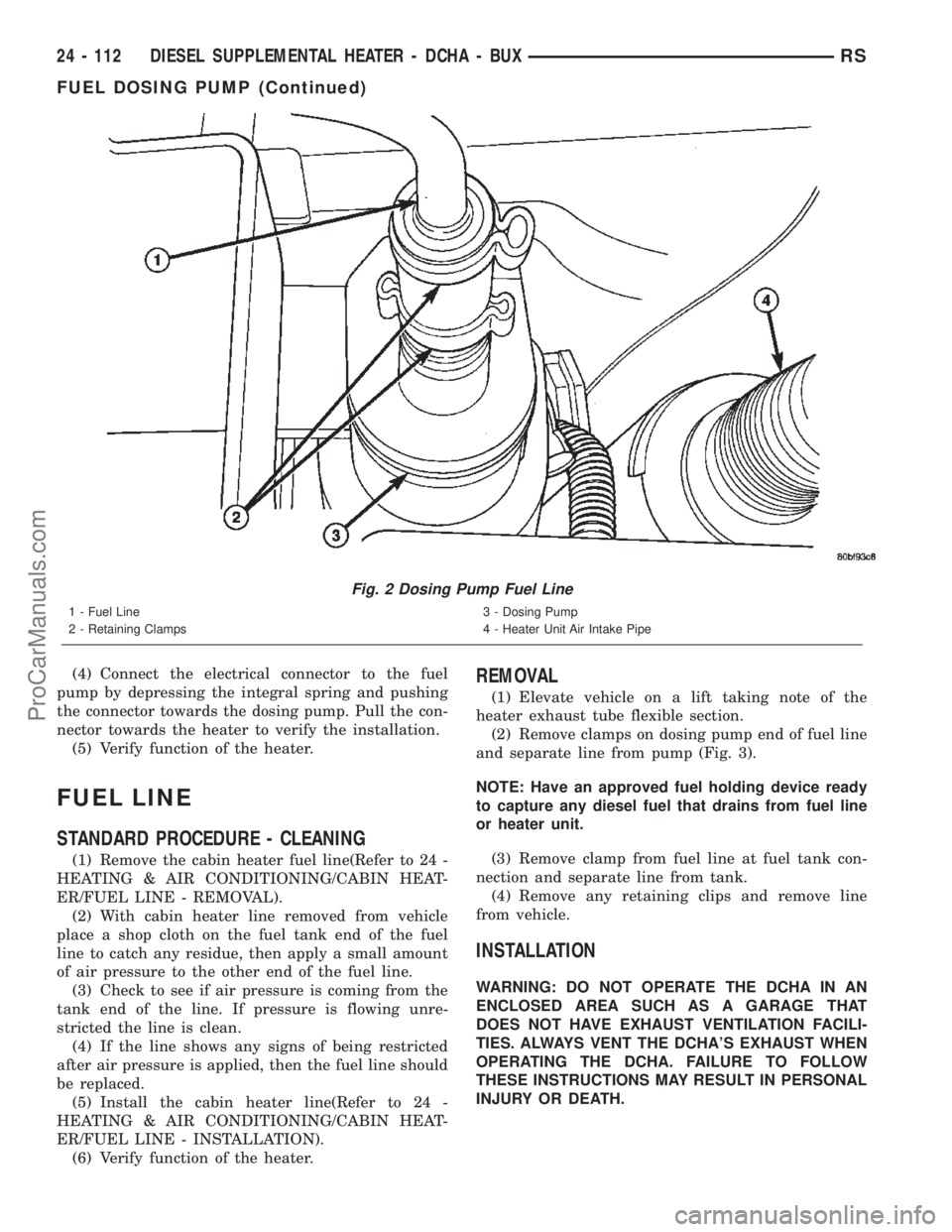
(2) Remove clamps on dosing pump end of fuel line
and separate line from pump (Fig. 3).
NOTE: Have an approved fuel holding device ready
to capture any diesel fuel that drains from fuel line
or heater unit.
(3) Remove clamp from fuel line at fuel tank con-
nection and separate line from tank.
(4) Remove any retaining clips and remove line
from vehicle.
INSTALLATION
WARNING: DO NOT OPERATE THE DCHA IN AN
ENCLOSED AREA SUCH AS A GARAGE THAT
DOES NOT HAVE EXHAUST VENTILATION FACILI-
TIES. ALWAYS VENT THE DCHA'S EXHAUST WHEN
OPERATING THE DCHA. FAILURE TO FOLLOW
THESE INSTRUCTIONS MAY RESULT IN PERSONAL
INJURY OR DEATH.
Fig. 2 Dosing Pump Fuel Line
1 - Fuel Line
2 - Retaining Clamps3 - Dosing Pump
4 - Heater Unit Air Intake Pipe
24 - 112 DIESEL SUPPLEMENTAL HEATER - DCHA - BUXRS
FUEL DOSING PUMP (Continued)
ProCarManuals.com
Page 2356 of 2399

WARNING: ALLOW THE DCHA ASSEMBLY TO
COOL BEFORE PERFORMING A COMPONENT
INSPECTION/REPAIR/REPLACEMENT. FAILURE TO
FOLLOW THESE INSTRUCTIONS MAY RESULT IN
PERSONAL INJURY.
WARNING: VERIFY THAT ALL DCHA FUEL LINES
ARE SECURELY FASTENED TO THEIR RESPECTIVE
COMPONENTS BEFORE PERFORMING THIS PRO-
CEDURE.
NOTE: Verify that there is more than 1/8 of a tank of
fuel in the vehicle's fuel tank before performing this
procedure. Add fuel, if necessary.
(1) Install heater fuel supply line to vehicle and
install in fuel line retainers
(2) Install fuel line connection at fuel tank and
tighten connection.
(3) Install fuel line at Dosing Pump and tighten
connection.
(4) Lower vehicle from lift.NOTE: Failure to prime the Dosing Pump after
draining the DCHA fuel line will prevent DCHA
heater activation during the first attempt to start the
heater. This will also set a Diagnostic Trouble Code
(DCT) in the DCHA Control's memory. do not per-
form the Dosing Pump Priming procedure if an
attempt was made to start the DCHA without prim-
ing the Dosing Pump first. This will put excess fuel
in the DCHA Heater Module and cause smoke to
emit from the DCHA exhaust pipe when heater acti-
vation occurs.
(5) Connect the DRBIIItto the Diagnostic Link
Connector.
(6) Turn the ignition to the on position.
NOTE: Do not activate the Dosing Pump Prime
more than one time. This will put excess fuel in the
DCHA Heater Module an cause smoke to emit from
the DCHA exhaust pipe when heater activation
occurs.
NOTE: A clicking noise heard coming from the Dos-
ing Pump indicates that the pump is operational.
Fig. 3 Dosing Pump Fuel Line
1 - Fuel Line
2 - Retaining Clamps3 - Dosing Pump
4 - Heater Unit Air Intake Pipe
RSDIESEL SUPPLEMENTAL HEATER - DCHA - BUX24 - 113
FUEL LINE (Continued)
ProCarManuals.com
Page 2358 of 2399
(12) Remove the heater unit support device from
under the vehicle.
(13) Lower vehicle from lift.
(14) Refill cooling system(Refer to 7 - COOLING -
STANDARD PROCEDURE).
(15) Verify function of the cabin heater.
SUPPLEMENTAL DIESEL
HEATER WIRING
REMOVAL
(1) Elevate vehicle on a lift taking note of the
exhaust tube flexible section.
(2) Unplug connector from vehicle wiring harness
to cabin heater harness.
(3) Unplug connector from cabin heater harness to
dosing pump connector.
(4) Unplug two connectors from cabin heater har-
ness to cabin heater controller connectors.
(5) Remove two wiring harness connectors from
underbody.
(6) Remove two wiring harness connectors from
cabin heater shield.
(7) Carefully route the cabin heater harness to the
left side between the cabin heater unit and the cabin
heater shield.
INSTALLATION
(1) Carefully route the cabin heater harness from
the left side of the cabin heater between the cabin
heater unit and the cabin heater shield.
(2) Install the two wiring harness retaining con-
nectors to the cabin heater shield.
(3) Route the wiring harness along the underside
of the vehicle and install the two wiring harness
retaining connectors.
(4) Plug the two connectors from the cabin heater
harness to the cabin heater controller.
(5) Plug the connector to the cabin heater harness
to the dosing pump connector.
(6) Plug the connector from the vehicle wiring har-
ness to the cabin heater harness.
(7) Lower the vehicle.
(8) Verify function of the cabin heater.
AIR INTAKE PIPE
REMOVAL
NOTE: Heater air intake tube is part of an assembly
that includes the heater cooling intake and return
pipes. If heater air intake tube requires removal or
replacement the entire assembly will require remov-
al/replacement.
(1) Drain cooling system(Refer to 7 - COOLING -
STANDARD PROCEDURE).
(2) Remove clamps from the heater tubes at the
lower heater port and the lower EGR connector
which are located under the hood.
(3) Remove the retaining clamp at the heater air
intake muffler connection(Refer to 24 - HEATING &
AIR CONDITIONING/CABIN HEATER/INLET
MUFFLER - REMOVAL).
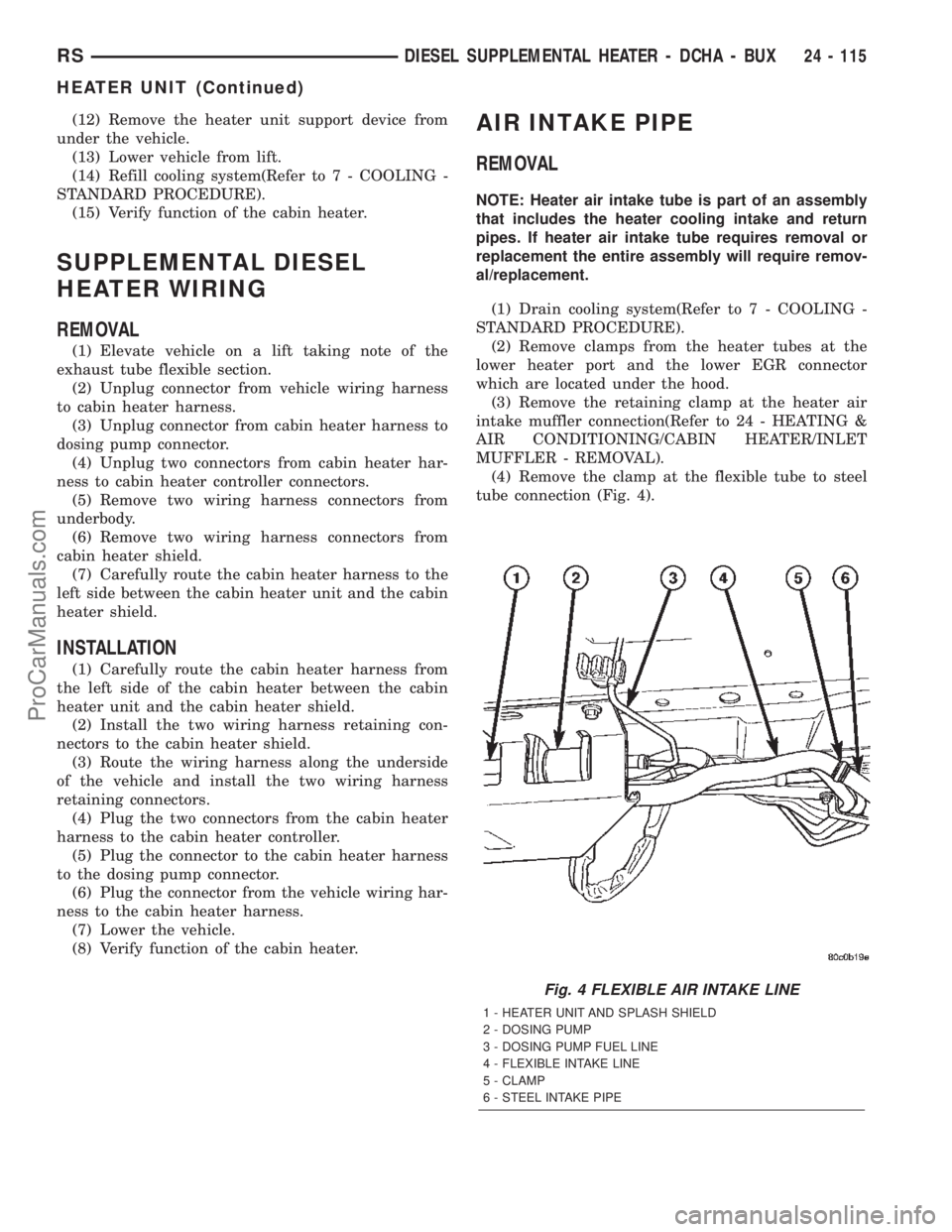
(4) Remove the clamp at the flexible tube to steel
tube connection (Fig. 4).
Fig. 4 FLEXIBLE AIR INTAKE LINE
1 - HEATER UNIT AND SPLASH SHIELD
2 - DOSING PUMP
3 - DOSING PUMP FUEL LINE
4 - FLEXIBLE INTAKE LINE
5 - CLAMP
6 - STEEL INTAKE PIPE
RSDIESEL SUPPLEMENTAL HEATER - DCHA - BUX24 - 115
HEATER UNIT (Continued)
ProCarManuals.com
Page 2359 of 2399
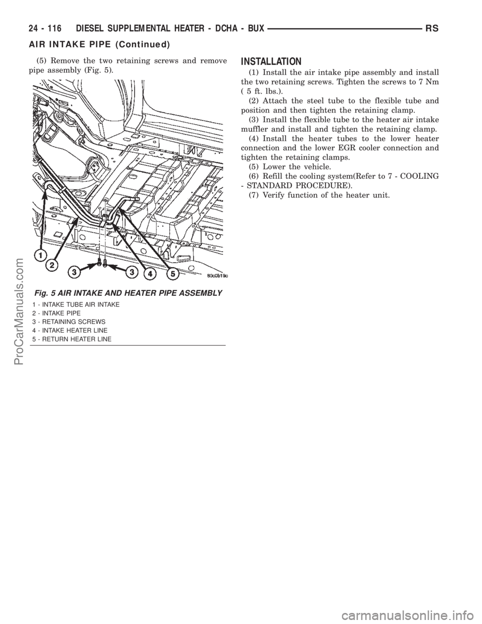
(5) Remove the two retaining screws and remove
pipe assembly (Fig. 5).INSTALLATION
(1) Install the air intake pipe assembly and install
the two retaining screws. Tighten the screws to 7 Nm
( 5 ft. lbs.).
(2) Attach the steel tube to the flexible tube and
position and then tighten the retaining clamp.
(3) Install the flexible tube to the heater air intake
muffler and install and tighten the retaining clamp.
(4) Install the heater tubes to the lower heater
connection and the lower EGR cooler connection and
tighten the retaining clamps.
(5) Lower the vehicle.
(6) Refill the cooling system(Refer to 7 - COOLING
- STANDARD PROCEDURE).
(7) Verify function of the heater unit.
Fig. 5 AIR INTAKE AND HEATER PIPE ASSEMBLY
1 - INTAKE TUBE AIR INTAKE
2 - INTAKE PIPE
3 - RETAINING SCREWS
4 - INTAKE HEATER LINE
5 - RETURN HEATER LINE
24 - 116 DIESEL SUPPLEMENTAL HEATER - DCHA - BUXRS
AIR INTAKE PIPE (Continued)
ProCarManuals.com
Page 2369 of 2399

Technicians can display stored DTC's. Refer to
Diagnostic Trouble Codes (Refer to 8 - ELECTRICAL/
ELECTRONIC CONTROL MODULES/POWER-
TRAIN CONTROL MODULE - DESCRIPTION). For
obtaining the DTC information, use the Data Link
Connector with the DRBIIItscan tool (Fig. 1).
DRB IIITSTATE DISPLAY TEST MODE
OPERATION
The switch inputs to the Powertrain Control Mod-
ule (PCM) have two recognized states; HIGH and
LOW. For this reason, the PCM cannot recognize the
difference between a selected switch position versus
an open circuit, a short circuit, or a defective switch.
If the State Display screen shows the change from
HIGH to LOW or LOW to HIGH, assume the entire
switch circuit to the PCM functions properly. From
the state display screen, access either State Display
Inputs and Outputs or State Display Sensors.
Fig. 1 Data Link Connector
25 - 10 EMISSIONS CONTROLRS
EMISSIONS CONTROL (Continued)
ProCarManuals.com
Page 2370 of 2399
EVAPORATIVE EMISSIONS
TABLE OF CONTENTS
page page
EVAPORATIVE EMISSIONS
OPERATION - EVAPORATION CONTROL
SYSTEM............................11
SPECIFICATIONS
TORQUE............................12
EVAP/PURGE SOLENOID
DESCRIPTION.........................13
OPERATION...........................13
REMOVAL.............................13
INSTALLATION.........................13
FUEL FILLER CAP
DESCRIPTION.........................13
OPERATION...........................13
LEAK DETECTION PUMP
REMOVAL.............................14
INSTALLATION.........................14
ORVR
OPERATION...........................14DIAGNOSIS AND TESTING - VEHICLE DOES
NOT FILL............................16
P C V VA LV E
DESCRIPTION.........................17
OPERATION...........................17
DIAGNOSIS AND TESTING - PCV SYSTEM . . . 17
VAPOR CANISTER
DESCRIPTION.........................18
OPERATION...........................18
REMOVAL
REMOVAL...........................19
REMOVAL - REAR EVAP CANISTER.......19
INSTALLATION
INSTALLATION.......................19
INSTALLATION - REAR EVAP CANISTER . . . 19
EVAPORATIVE EMISSIONS
OPERATION - EVAPORATION CONTROL
SYSTEM
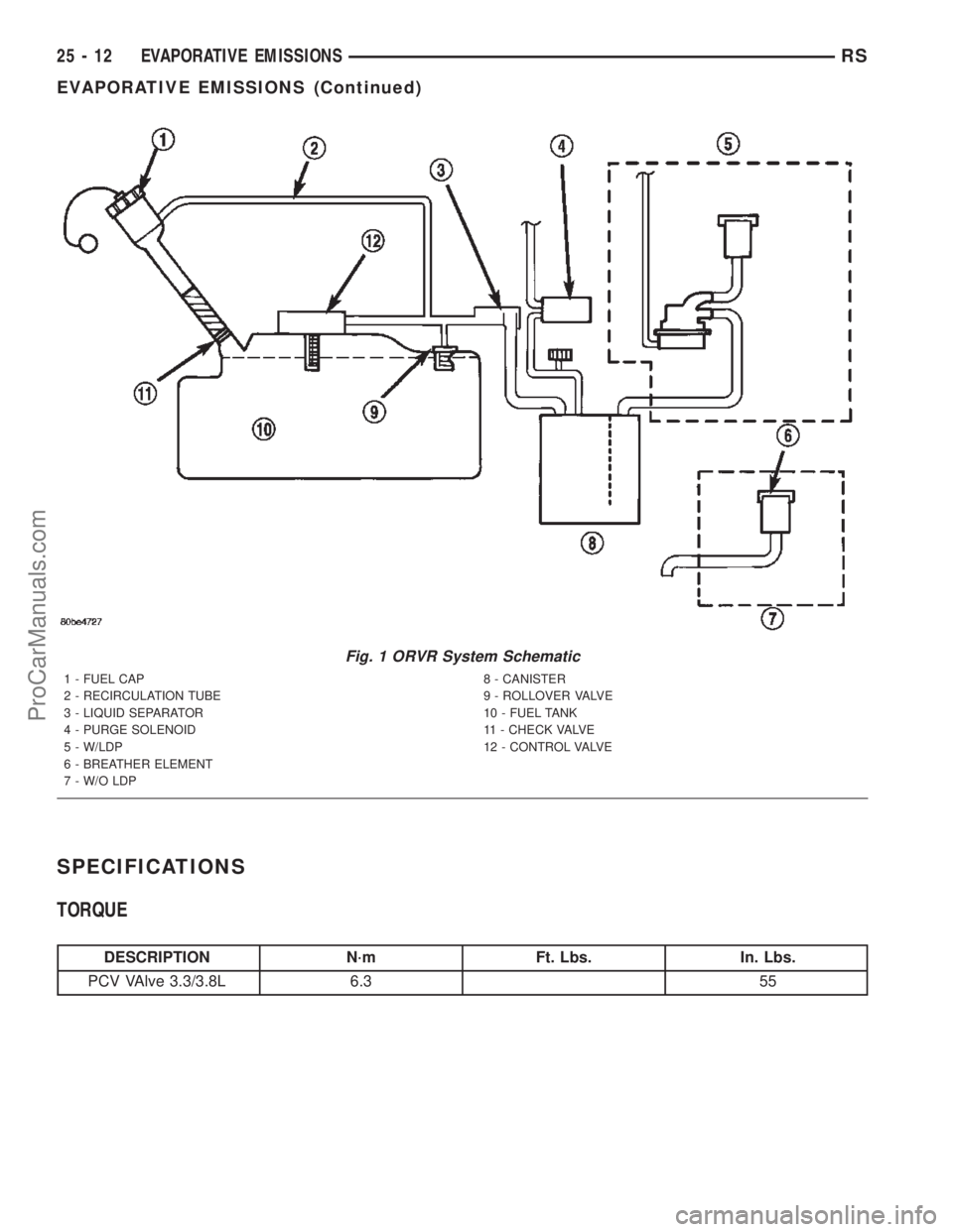
The evaporation control system prevents the emis-
sion of fuel tank vapors into the atmosphere. When
fuel evaporates in the fuel tank, the vapors pass
through vent hoses or tubes to an activated carbon
filled evaporative canister. The canister temporarily
holds the vapors. The Powertrain Control Module
(PCM) allows intake manifold vacuum to draw
vapors into the combustion chambers during certain
operating conditions (Fig. 1).All engines use a proportional purge solenoid sys-
tem. The PCM controls vapor flow by operating the
purge solenoid. Refer to Proportional Purge Solenoid
in this section.
NOTE: The evaporative system uses specially man-
ufactured hoses. If they need replacement, only use
fuel resistant hose. Also the hoses must be able to
pass an Ozone compliance test.
NOTE: For more information on Onboard Refueling
Vapor Recovery (ORVR), refer to the Fuel Delivery
section.
RSEVAPORATIVE EMISSIONS25-11
ProCarManuals.com
Page 2371 of 2399
SPECIFICATIONS
TORQUE
DESCRIPTION N´m Ft. Lbs. In. Lbs.
PCV VAlve 3.3/3.8L 6.3 55
Fig. 1 ORVR System Schematic
1 - FUEL CAP
2 - RECIRCULATION TUBE
3 - LIQUID SEPARATOR
4 - PURGE SOLENOID
5 - W/LDP
6 - BREATHER ELEMENT
7 - W/O LDP8 - CANISTER
9 - ROLLOVER VALVE
10 - FUEL TANK
11 - CHECK VALVE
12 - CONTROL VALVE
25 - 12 EVAPORATIVE EMISSIONSRS
EVAPORATIVE EMISSIONS (Continued)
ProCarManuals.com
Page 2372 of 2399
EVAP/PURGE SOLENOID
DESCRIPTION
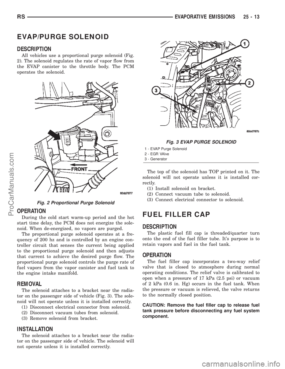
All vehicles use a proportional purge solenoid (Fig.
2). The solenoid regulates the rate of vapor flow from
the EVAP canister to the throttle body. The PCM
operates the solenoid.
OPERATION
During the cold start warm-up period and the hot
start time delay, the PCM does not energize the sole-
noid. When de-energized, no vapors are purged.
The proportional purge solenoid operates at a fre-
quency of 200 hz and is controlled by an engine con-
troller circuit that senses the current being applied
to the proportional purge solenoid and then adjusts
that current to achieve the desired purge flow. The
proportional purge solenoid controls the purge rate of
fuel vapors from the vapor canister and fuel tank to
the engine intake manifold.
REMOVAL
The solenoid attaches to a bracket near the radia-
tor on the passenger side of vehicle (Fig. 3). The sole-
noid will not operate unless it is installed correctly.
(1) Disconnect electrical connector from solenoid.
(2) Disconnect vacuum tubes from solenoid.
(3) Remove solenoid from bracket.
INSTALLATION
The solenoid attaches to a bracket near the radia-
tor on the passenger side of vehicle. The solenoid will
not operate unless it is installed correctly.The top of the solenoid has TOP printed on it. The
solenoid will not operate unless it is installed cor-
rectly.
(1) Install solenoid on bracket.
(2) Connect vacuum tube to solenoid.
(3) Connect electrical connector to solenoid.
FUEL FILLER CAP
DESCRIPTION
The plastic fuel fill cap is threaded/quarter turn
onto the end of the fuel filler tube. It's purpose is to
retain vapors and fuel in the fuel tank.
OPERATION
The fuel filler cap incorporates a two-way relief
valve that is closed to atmosphere during normal
operating conditions. The relief valve is calibrated to
open when a pressure of 17 kPa (2.5 psi) or vacuum
of 2 kPa (0.6 in. Hg) occurs in the fuel tank. When
the pressure or vacuum is relieved, the valve returns
to the normally closed position.
CAUTION: Remove the fuel filler cap to release fuel
tank pressure before disconnecting any fuel system
component.
Fig. 2 Proportional Purge Solenoid
Fig. 3 EVAP PURGE SOLENOID
1 - EVAP Purge Solenoid
2 - EGR VAlve
3 - Generator
RSEVAPORATIVE EMISSIONS25-13
ProCarManuals.com
Page 2373 of 2399
LEAK DETECTION PUMP
REMOVAL
(1) Disconnect the negative battery cable.
(2) Raise and support the vehicle.
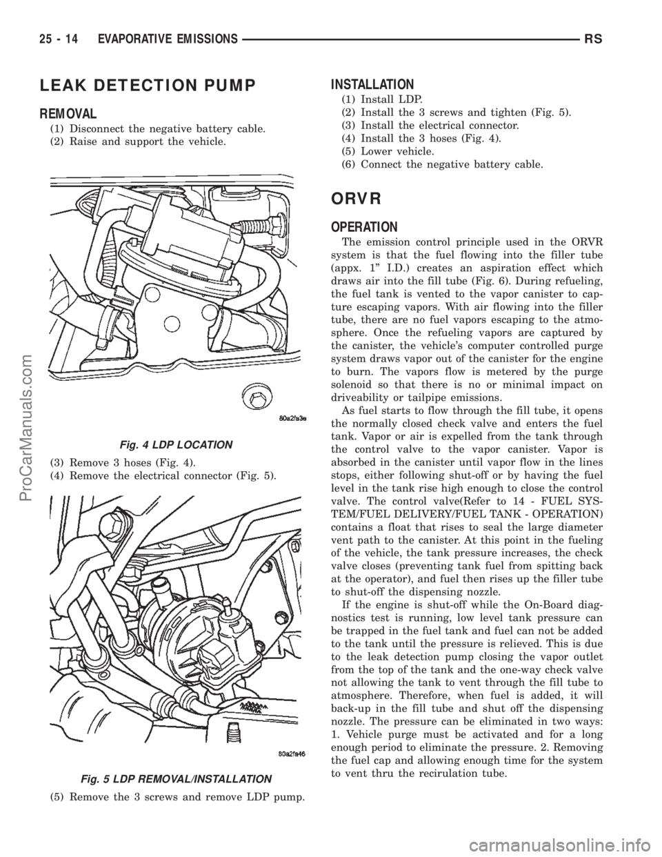
(3) Remove 3 hoses (Fig. 4).
(4) Remove the electrical connector (Fig. 5).
(5) Remove the 3 screws and remove LDP pump.
INSTALLATION
(1) Install LDP.
(2) Install the 3 screws and tighten (Fig. 5).
(3) Install the electrical connector.
(4) Install the 3 hoses (Fig. 4).
(5) Lower vehicle.
(6) Connect the negative battery cable.
ORVR
OPERATION
The emission control principle used in the ORVR
system is that the fuel flowing into the filler tube
(appx. 1º I.D.) creates an aspiration effect which
draws air into the fill tube (Fig. 6). During refueling,
the fuel tank is vented to the vapor canister to cap-
ture escaping vapors. With air flowing into the filler
tube, there are no fuel vapors escaping to the atmo-
sphere. Once the refueling vapors are captured by
the canister, the vehicle's computer controlled purge
system draws vapor out of the canister for the engine
to burn. The vapors flow is metered by the purge
solenoid so that there is no or minimal impact on
driveability or tailpipe emissions.
As fuel starts to flow through the fill tube, it opens
the normally closed check valve and enters the fuel
tank. Vapor or air is expelled from the tank through
the control valve to the vapor canister. Vapor is
absorbed in the canister until vapor flow in the lines
stops, either following shut-off or by having the fuel
level in the tank rise high enough to close the control
valve. The control valve(Refer to 14 - FUEL SYS-
TEM/FUEL DELIVERY/FUEL TANK - OPERATION)
contains a float that rises to seal the large diameter
vent path to the canister. At this point in the fueling
of the vehicle, the tank pressure increases, the check
valve closes (preventing tank fuel from spitting back
at the operator), and fuel then rises up the filler tube
to shut-off the dispensing nozzle.
If the engine is shut-off while the On-Board diag-
nostics test is running, low level tank pressure can
be trapped in the fuel tank and fuel can not be added
to the tank until the pressure is relieved. This is due
to the leak detection pump closing the vapor outlet
from the top of the tank and the one-way check valve
not allowing the tank to vent through the fill tube to
atmosphere. Therefore, when fuel is added, it will
back-up in the fill tube and shut off the dispensing
nozzle. The pressure can be eliminated in two ways:
1. Vehicle purge must be activated and for a long
enough period to eliminate the pressure. 2. Removing
the fuel cap and allowing enough time for the system
to vent thru the recirulation tube.
Fig. 4 LDP LOCATION
Fig. 5 LDP REMOVAL/INSTALLATION
25 - 14 EVAPORATIVE EMISSIONSRS
ProCarManuals.com
Page 2374 of 2399
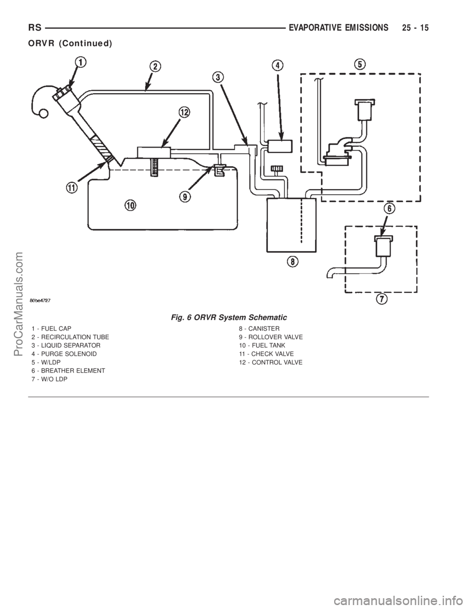
Fig. 6 ORVR System Schematic
1 - FUEL CAP
2 - RECIRCULATION TUBE
3 - LIQUID SEPARATOR
4 - PURGE SOLENOID
5 - W/LDP
6 - BREATHER ELEMENT
7 - W/O LDP8 - CANISTER
9 - ROLLOVER VALVE
10 - FUEL TANK
11 - CHECK VALVE
12 - CONTROL VALVE
RSEVAPORATIVE EMISSIONS25-15
ORVR (Continued)
ProCarManuals.com