ECU CHRYSLER CARAVAN 2002 User Guide
[x] Cancel search | Manufacturer: CHRYSLER, Model Year: 2002, Model line: CARAVAN, Model: CHRYSLER CARAVAN 2002Pages: 2399, PDF Size: 57.96 MB
Page 64 of 2399
(4) Using 2 jack stands positioned under the outer
ends of the axle, raise the axle enough to remove the
weight of the axle from the rear springs.
(5) Loosen and remove the spring plate bolts from
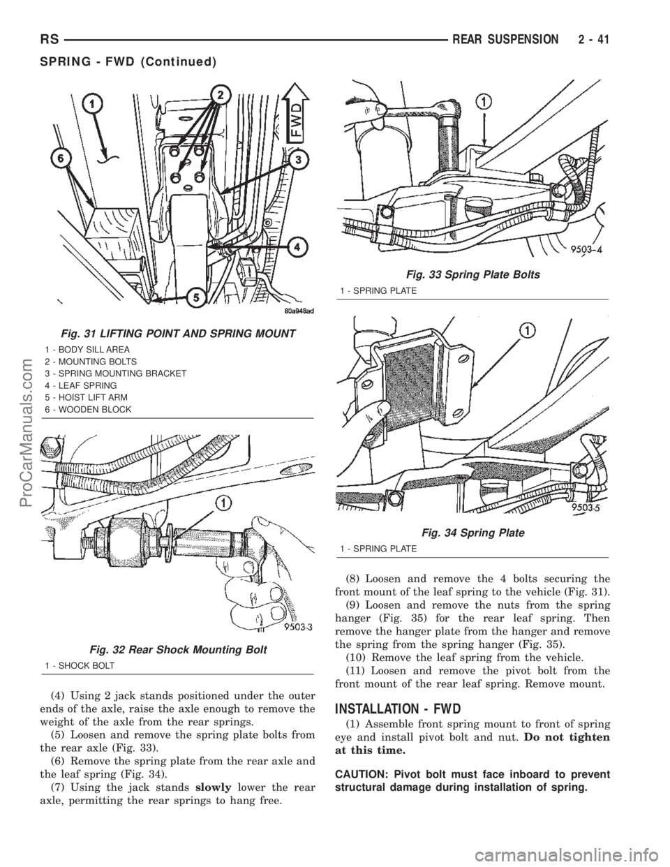
the rear axle (Fig. 33).
(6) Remove the spring plate from the rear axle and
the leaf spring (Fig. 34).
(7) Using the jack standsslowlylower the rear
axle, permitting the rear springs to hang free.(8) Loosen and remove the 4 bolts securing the
front mount of the leaf spring to the vehicle (Fig. 31).
(9) Loosen and remove the nuts from the spring
hanger (Fig. 35) for the rear leaf spring. Then
remove the hanger plate from the hanger and remove
the spring from the spring hanger (Fig. 35).
(10) Remove the leaf spring from the vehicle.
(11) Loosen and remove the pivot bolt from the
front mount of the rear leaf spring. Remove mount.
INSTALLATION - FWD
(1) Assemble front spring mount to front of spring
eye and install pivot bolt and nut.Do not tighten
at this time.
CAUTION: Pivot bolt must face inboard to prevent
structural damage during installation of spring.
Fig. 31 LIFTING POINT AND SPRING MOUNT
1 - BODY SILL AREA
2 - MOUNTING BOLTS
3 - SPRING MOUNTING BRACKET
4 - LEAF SPRING
5 - HOIST LIFT ARM
6 - WOODEN BLOCK
Fig. 32 Rear Shock Mounting Bolt
1 - SHOCK BOLT
Fig. 33 Spring Plate Bolts
1 - SPRING PLATE
Fig. 34 Spring Plate
1 - SPRING PLATE
RSREAR SUSPENSION2-41
SPRING - FWD (Continued)
ProCarManuals.com
Page 65 of 2399
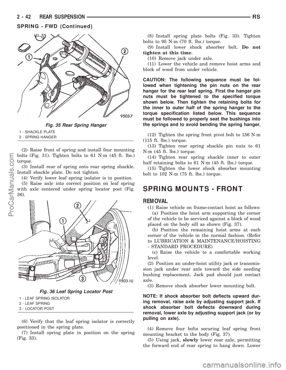
(2) Raise front of spring and install four mounting
bolts (Fig. 31). Tighten bolts to 61 N´m (45 ft. lbs.)
torque.
(3) Install rear of spring onto rear spring shackle.
Install shackle plate. Do not tighten.
(4) Verify lower leaf spring isolator is in position.
(5) Raise axle into correct position on leaf spring
with axle centered under spring locator post (Fig.
36).
(6) Verify that the leaf spring isolator is correctly
positioned in the spring plate.
(7) Install spring plate in position on the spring
(Fig. 33).(8) Install spring plate bolts (Fig. 33). Tighten
bolts to 95 N´m (70 ft. lbs.) torque.
(9) Install lower shock absorber bolt.Do not
tighten at this time.
(10) Remove jack under axle.
(11) Lower the vehicle and remove hoist arms and
block of wood from under vehicle.
CAUTION: The following sequence must be fol-
lowed when tightening the pin nuts on the rear
hanger for the rear leaf spring. First the hanger pin
nuts must be tightened to the specified torque
shown below. Then tighten the retaining bolts for
the inner to outer half of the spring hanger to the
torque specification listed below. This sequence
must be followed to properly seat the bushings into
the springs and to avoid bending the spring hanger.
(12) Tighten the spring front pivot bolt to 156 N´m
(115 ft. lbs.) torque.
(13) Tighten rear spring shackle pin nuts to 61
N´m (45 ft. lbs.) torque.
(14) Tighten rear spring shackle inner to outer
half retaining bolts to 61 N´m (45 ft. lbs.) torque.
(15) Tighten the lower shock absorber mounting
bolt to 102 N´m (75 ft. lbs.) torque.
SPRING MOUNTS - FRONT
REMOVAL
(1) Raise vehicle on frame-contact hoist as follows:
(a) Position the hoist arm supporting the corner
of the vehicle to be serviced against a block of wood
placed on the body sill as shown (Fig. 37).
(b) Position the remaining hoist arms at each
corner of the vehicle in the normal fashion. (Refer
to LUBRICATION & MAINTENANCE/HOISTING
- STANDARD PROCEDURE)
(c) Raise the vehicle to a comfortable working
level.
(2) Position an under-hoist utility jack or transmis-
sion jack under rear axle toward the side needing
bushing replacement. Jack pad should just contact
axle.
(3) Remove shock absorber lower mounting bolt.
NOTE: If shock absorber bolt deflects upward dur-
ing removal, raise axle by adjusting support jack. If
shock absorber bolt deflects downward during
removal, lower axle by adjusting support jack (or by
pulling on axle).
(4) Remove four bolts securing leaf spring front
mounting bracket to the body (Fig. 37).
(5) Using jack,slowlylower rear axle, permitting
the forward end of rear spring to hang down. Lower
Fig. 35 Rear Spring Hanger
1 - SHACKLE PLATE
2 - SPRING HANGER
Fig. 36 Leaf Spring Locator Post
1 - LEAF SPRING ISOLATOR
2 - LEAF SPRING
3 - LOCATOR POST
2 - 42 REAR SUSPENSIONRS
SPRING - FWD (Continued)
ProCarManuals.com
Page 67 of 2399
(2)Install a jackstand under the side of the axle
having the leaf spring mount removed. Using the jack-
stand, support the weight of the axle and leaf spring.
(3) Remove the lower mounting bolt from the
shock absorber.
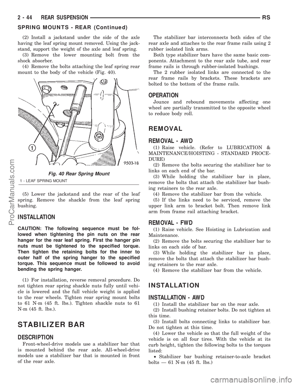
(4) Remove the bolts attaching the leaf spring rear
mount to the body of the vehicle (Fig. 40).
(5) Lower the jackstand and the rear of the leaf
spring. Remove the shackle from the leaf spring
bushing.
INSTALLATION
CAUTION: The following sequence must be fol-
lowed when tightening the pin nuts on the rear
hanger for the rear leaf spring. First the hanger pin
nuts must be tightened to the specified torque.
Then tighten the retaining bolts for the inner to
outer half of the spring hanger to the specified
torque. This sequence must be followed to avoid
bending the spring hanger.
(1) For installation, reverse removal procedure. Do
not tighten rear spring shackle nuts fully until vehi-
cle is lowered and the full vehicle weight is applied
to the rear wheels. Tighten rear spring mount bolts
to 61 N´m (45 ft. lbs.). Tighten shackle nuts to 61
N´m (45 ft. lbs.).
STABILIZER BAR
DESCRIPTION
Front-wheel-drive models use a stabilizer bar that
is mounted behind the rear axle. All-wheel-drive
models use a stabilizer bar that is mounted in front
of the rear axle.The stabilizer bar interconnects both sides of the
rear axle and attaches to the rear frame rails using 2
rubber isolated link arms.
Both type stabilizer bars have the same basic com-
ponents. Attachment to the rear axle tube, and rear
frame rails is through rubber-isolated bushings.
The 2 rubber isolated links are connected to the
rear frame rails by brackets. These brackets are
bolted to the bottom of the frame rails.
OPERATION
Jounce and rebound movements affecting one
wheel are partially transmitted to the opposite wheel
to reduce body roll.
REMOVAL
REMOVAL - AWD
(1) Raise vehicle. (Refer to LUBRICATION &
MAINTENANCE/HOISTING - STANDARD PROCE-
DURE)
(2) Remove the bolts securing the stabilizer bar to
links on each end of the bar.
(3) While holding the stabilizer bar in place,
remove the bolts that attach the stabilizer bar bush-
ing retainers to the rear axle.
(4) Remove the stabilizer bar from the vehicle.
(5) If the links need to be serviced, remove the
upper link arm to bracket bolt. Then remove link
arm from frame rail attaching bracket.
REMOVAL - FWD
(1) Raise vehicle. See Hoisting in Lubrication and
Maintenance.
(2) Remove the bolts securing the stabilizer bar to
links on each side of bar.
(3) While holding the stabilizer bar in place,
remove the bolts that attach the stabilizer bar bush-
ing retainers to the rear axle.
(4) Remove the stabilizer bar from the vehicle.
INSTALLATION
INSTALLATION - AWD
(1) Install the stabilizer bar on the rear axle.
(2) Install bushing retainer bolts. Do not tighten at
this time.
(3) Install bolts connecting links to stabilizer bar.
Do not tighten at this time.
(4) Lower the vehicle so that the full weight of the
vehicle is on all four tires. With the vehicle at its
curb height, tighten the following bolts to the torques
listed:
²Stabilizer bar bushing retainer-to-axle bracket
bolts Ð 61 N´m (45 ft. lbs.)
Fig. 40 Rear Spring Mount
1 - LEAF SPRING MOUNT
2 - 44 REAR SUSPENSIONRS
SPRING MOUNTS - REAR (Continued)
ProCarManuals.com
Page 84 of 2399
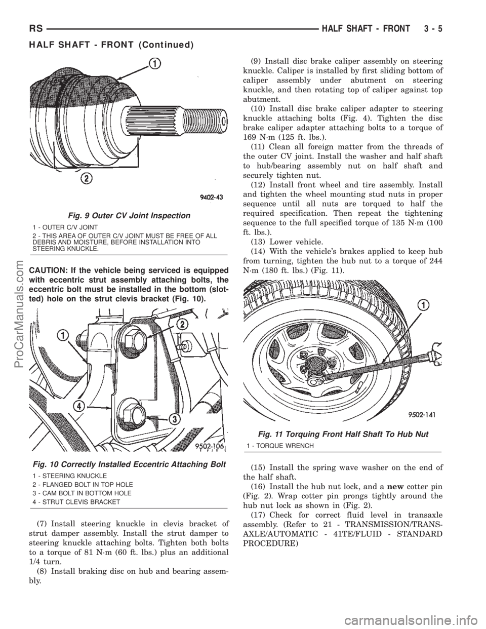
CAUTION: If the vehicle being serviced is equipped
with eccentric strut assembly attaching bolts, the
eccentric bolt must be installed in the bottom (slot-
ted) hole on the strut clevis bracket (Fig. 10).
(7) Install steering knuckle in clevis bracket of
strut damper assembly. Install the strut damper to
steering knuckle attaching bolts. Tighten both bolts
to a torque of 81 N´m (60 ft. lbs.) plus an additional
1/4 turn.
(8) Install braking disc on hub and bearing assem-
bly.(9) Install disc brake caliper assembly on steering
knuckle. Caliper is installed by first sliding bottom of
caliper assembly under abutment on steering
knuckle, and then rotating top of caliper against top
abutment.
(10) Install disc brake caliper adapter to steering
knuckle attaching bolts (Fig. 4). Tighten the disc
brake caliper adapter attaching bolts to a torque of
169 N´m (125 ft. lbs.).
(11) Clean all foreign matter from the threads of
the outer CV joint. Install the washer and half shaft
to hub/bearing assembly nut on half shaft and
securely tighten nut.
(12) Install front wheel and tire assembly. Install
and tighten the wheel mounting stud nuts in proper
sequence until all nuts are torqued to half the
required specification. Then repeat the tightening
sequence to the full specified torque of 135 N´m (100
ft. lbs.).
(13) Lower vehicle.
(14) With the vehicle's brakes applied to keep hub
from turning, tighten the hub nut to a torque of 244
N´m (180 ft. lbs.) (Fig. 11).
(15) Install the spring wave washer on the end of
the half shaft.
(16) Install the hub nut lock, and anewcotter pin
(Fig. 2). Wrap cotter pin prongs tightly around the
hub nut lock as shown in (Fig. 2).
(17) Check for correct fluid level in transaxle
assembly. (Refer to 21 - TRANSMISSION/TRANS-
AXLE/AUTOMATIC - 41TE/FLUID - STANDARD
PROCEDURE)
Fig. 9 Outer CV Joint Inspection
1 - OUTER C/V JOINT
2 - THIS AREA OF OUTER C/V JOINT MUST BE FREE OF ALL
DEBRIS AND MOISTURE, BEFORE INSTALLATION INTO
STEERING KNUCKLE.
Fig. 10 Correctly Installed Eccentric Attaching Bolt
1 - STEERING KNUCKLE
2 - FLANGED BOLT IN TOP HOLE
3 - CAM BOLT IN BOTTOM HOLE
4 - STRUT CLEVIS BRACKET
Fig. 11 Torquing Front Half Shaft To Hub Nut
1 - TORQUE WRENCH
RSHALF SHAFT - FRONT3-5
HALF SHAFT - FRONT (Continued)
ProCarManuals.com
Page 94 of 2399

REMOVAL
(1) Lift vehicle on hoist so that the wheels hang
freely.
(2) Remove rear wheel.
(3) Remove cotter pin, nut lock, and wave washer
(Fig. 1).
(4) Remove hub nut and washer.
CAUTION: The half shaft outer CV joint, when
installed, acts as a bolt and secures the hub/bear-
ing assembly. If the vehicle is to be supported or
moved on its wheels, install and torque a bolt
through the hub. This will ensure that the hub/bear-
ing assembly cannot loosen.
(5) Remove inner half shaft retaining bolts (Fig. 2).(6) The half shaft is spring loaded. Compress inner
half shaft joint slightly and pull downward to clear
rear differential output flange. Then pull half shaft
assembly outward to remove (Fig. 3).
INSTALLATION
(1) Install the outer CV joint stub shaft through
the hub bearing (Fig. 4).
(2) The half shaft is spring loaded. Compress inner
half shaft joint slightly and push upward until the
inner CV joint flange engages the rear differential
output flange.
(3) Install the inner half shaft retaining bolts (Fig.
5). Torque the bolts to 61 N´m (45 ft.lbs.).
Fig. 1 Cotter Pin, Nut Lock, And Wave Washer
1 - HUB NUT
2 - NUT LOCK
3 - COTTER PIN
4 - SPRING WASHER
Fig. 2 Inner Half Shaft Bolts
1 - SHAFT
2 - FLANGE
Fig. 3 Half Shaft Removal
1 - BRAKE BACKING PLATE
2 - HALF SHAFT
Fig. 4 Half Shaft Installation
1 - BRAKE BACKING PLATE
2 - HALF SHAFT
RSHALF SHAFT - REAR3-15
HALF SHAFT - REAR (Continued)
ProCarManuals.com
Page 106 of 2399
DIAGNOSIS AND TESTING - REAR DRIVELINE
MODULE OPERATION
Driveline module operation requires relatively
straight-forward diagnosis. Refer to the following
chart:
DRIVELINE MODULE DIAGNOSIS CHART
CONDITION POSSIBLE CAUSES CORRECTION
Rear wheels not
overrunning1) Bi-directional overrunning clutch
failure1) Replace overrunning clutch
components as required
No AWD in forward or
reverse directions, propeller
shaft turning1) Bi-directional overrunning clutch
failure1) Replace overrunning clutch
components as required
2) Viscous coupling failure 2) Replace viscous coupling
3) Rear differential failure 3) Replace the rear differential
assembly
No AWD in forward or
reverse directions, propeller
shaft not turning1) Power transfer unit failure. 1) Replace power transfer unit
components as necessary
Vibration at all speeds,
continuous torque transfer1) Mis-matched tires, worn tires on
front axle.1) Replace worn or incorrect
(mis-matched) tires with same
make and size
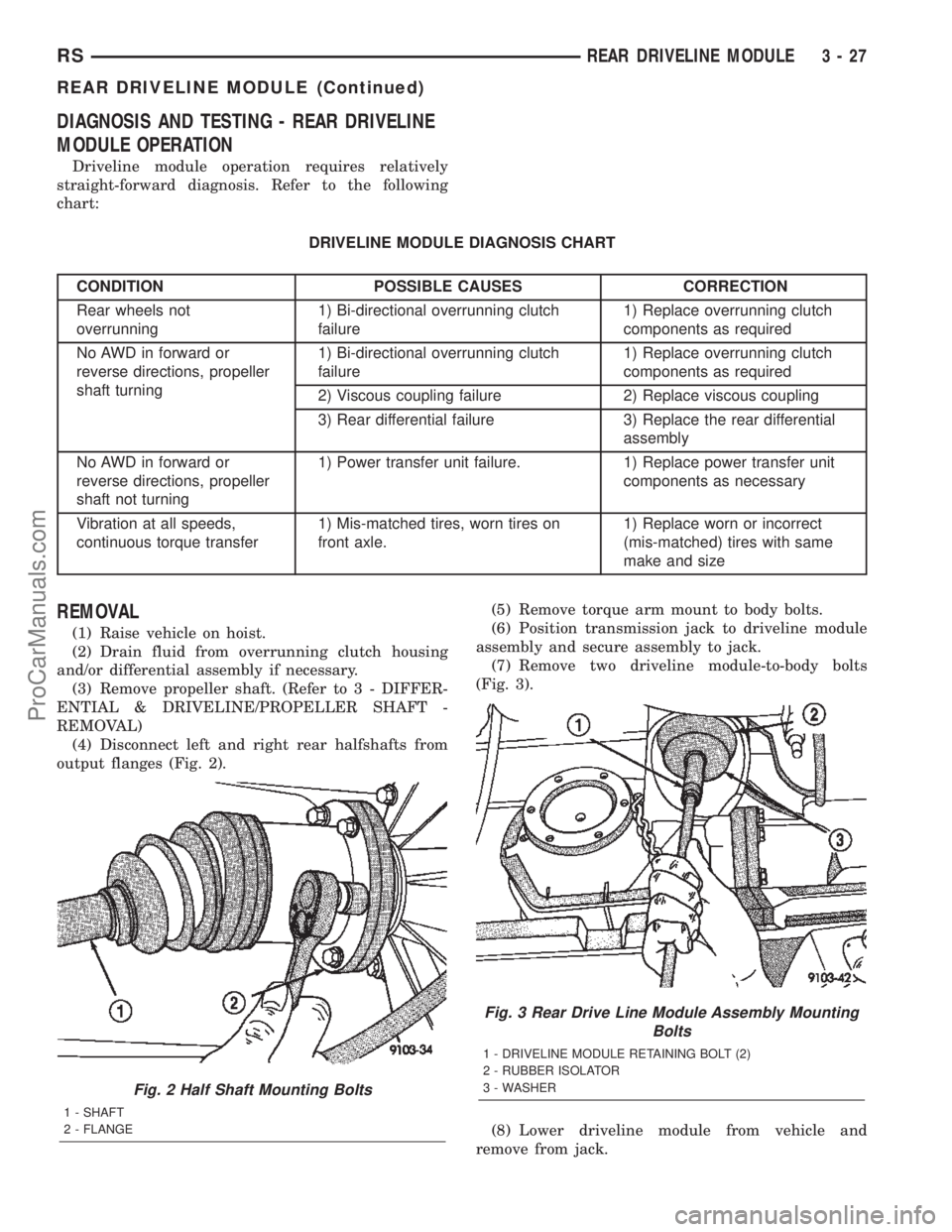
REMOVAL
(1) Raise vehicle on hoist.
(2) Drain fluid from overrunning clutch housing
and/or differential assembly if necessary.
(3) Remove propeller shaft. (Refer to 3 - DIFFER-
ENTIAL & DRIVELINE/PROPELLER SHAFT -
REMOVAL)
(4) Disconnect left and right rear halfshafts from
output flanges (Fig. 2).(5) Remove torque arm mount to body bolts.
(6) Position transmission jack to driveline module
assembly and secure assembly to jack.
(7) Remove two driveline module-to-body bolts
(Fig. 3).
(8) Lower driveline module from vehicle and
remove from jack.
Fig. 2 Half Shaft Mounting Bolts
1 - SHAFT
2 - FLANGE
Fig. 3 Rear Drive Line Module Assembly Mounting
Bolts
1 - DRIVELINE MODULE RETAINING BOLT (2)
2 - RUBBER ISOLATOR
3 - WASHER
RSREAR DRIVELINE MODULE3-27
REAR DRIVELINE MODULE (Continued)
ProCarManuals.com
Page 113 of 2399

(14) Install torque arm assembly into position.
Install and torque torque arm-to-differential assem-
bly bolts (Fig. 25) to 60 N´m (44 ft. lbs.).
INSTALLATION
(1) Install rear driveline module assembly to
transmission jack and secure.
(2) Raise rear driveline module into position and
install and torque mounting bolts (Fig. 26) to 54 N´m
(40 ft. lbs.).(3) Remove transmission jack.
(4) Install and torque torque arm mount-to-body
bolts to 54 N´m (40 ft. lbs.).
(5) Install halfshafts to differential output flanges
and torque bolts (Fig. 27) to 61 N´m (45 ft. lbs.).
(6) Install propeller shaft. (Refer to 3 - DIFFER-
ENTIAL & DRIVELINE/PROPELLER SHAFT -
INSTALLATION)
(7) Lower vehicle.
Fig. 25 Torque Arm Fasteners
1 - TORQUE ARM ASSEMBLY
2 - BOLT (SIX)
Fig. 26 Rear Drive Line Module Assembly Rear
Mounting Bolts
1 - DRIVELINE MODULE RETAINING BOLT (2)
2 - RUBBER ISOLATOR
3 - WASHER
Fig. 27 Half Shaft Mounting Bolts
1 - SHAFT
2 - FLANGE
3 - 34 REAR DRIVELINE MODULERS
REAR DRIVELINE MODULE (Continued)
ProCarManuals.com
Page 140 of 2399
ADJUSTABLE PEDAL SWITCH
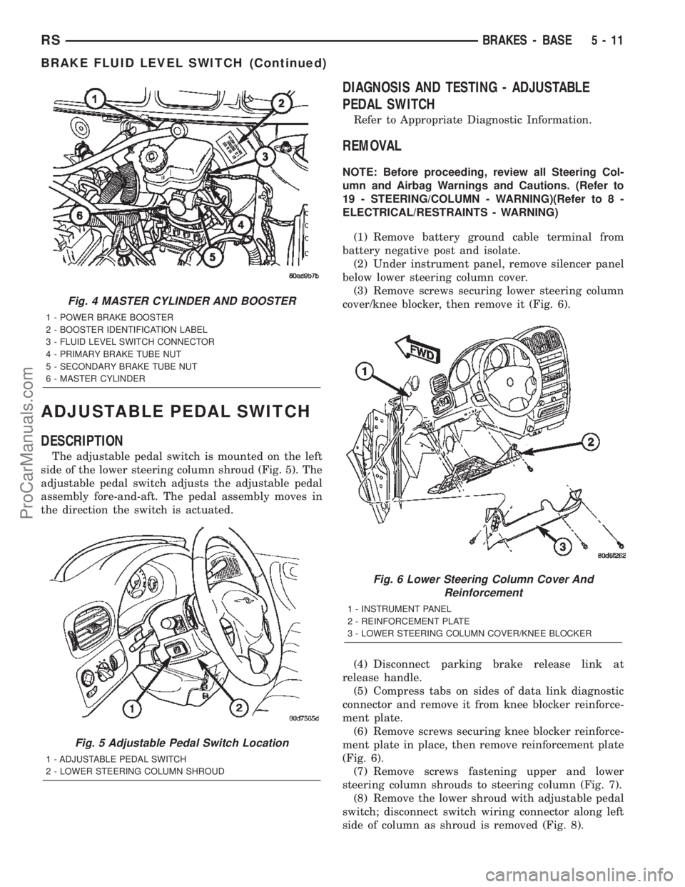
DESCRIPTION
The adjustable pedal switch is mounted on the left
side of the lower steering column shroud (Fig. 5). The
adjustable pedal switch adjusts the adjustable pedal
assembly fore-and-aft. The pedal assembly moves in
the direction the switch is actuated.
DIAGNOSIS AND TESTING - ADJUSTABLE
PEDAL SWITCH
Refer to Appropriate Diagnostic Information.
REMOVAL
NOTE: Before proceeding, review all Steering Col-
umn and Airbag Warnings and Cautions. (Refer to
19 - STEERING/COLUMN - WARNING)(Refer to 8 -
ELECTRICAL/RESTRAINTS - WARNING)
(1) Remove battery ground cable terminal from
battery negative post and isolate.
(2) Under instrument panel, remove silencer panel
below lower steering column cover.
(3) Remove screws securing lower steering column
cover/knee blocker, then remove it (Fig. 6).
(4) Disconnect parking brake release link at
release handle.
(5) Compress tabs on sides of data link diagnostic
connector and remove it from knee blocker reinforce-
ment plate.
(6) Remove screws securing knee blocker reinforce-
ment plate in place, then remove reinforcement plate
(Fig. 6).
(7) Remove screws fastening upper and lower
steering column shrouds to steering column (Fig. 7).
(8) Remove the lower shroud with adjustable pedal
switch; disconnect switch wiring connector along left
side of column as shroud is removed (Fig. 8).
Fig. 4 MASTER CYLINDER AND BOOSTER
1 - POWER BRAKE BOOSTER
2 - BOOSTER IDENTIFICATION LABEL
3 - FLUID LEVEL SWITCH CONNECTOR
4 - PRIMARY BRAKE TUBE NUT
5 - SECONDARY BRAKE TUBE NUT
6 - MASTER CYLINDER
Fig. 5 Adjustable Pedal Switch Location
1 - ADJUSTABLE PEDAL SWITCH
2 - LOWER STEERING COLUMN SHROUD
Fig. 6 Lower Steering Column Cover And
Reinforcement
1 - INSTRUMENT PANEL
2 - REINFORCEMENT PLATE
3 - LOWER STEERING COLUMN COVER/KNEE BLOCKER
RSBRAKES - BASE5-11
BRAKE FLUID LEVEL SWITCH (Continued)
ProCarManuals.com
Page 142 of 2399
DIAGNOSIS AND TESTING - PEDAL POSITION
SENSOR
Refer to Appropriate Diagnostic Information.
REMOVAL
(1) Remove battery ground cable terminal from
battery negative post and isolate.
(2) Under instrument panel, remove silencer panel
below lower steering column cover.
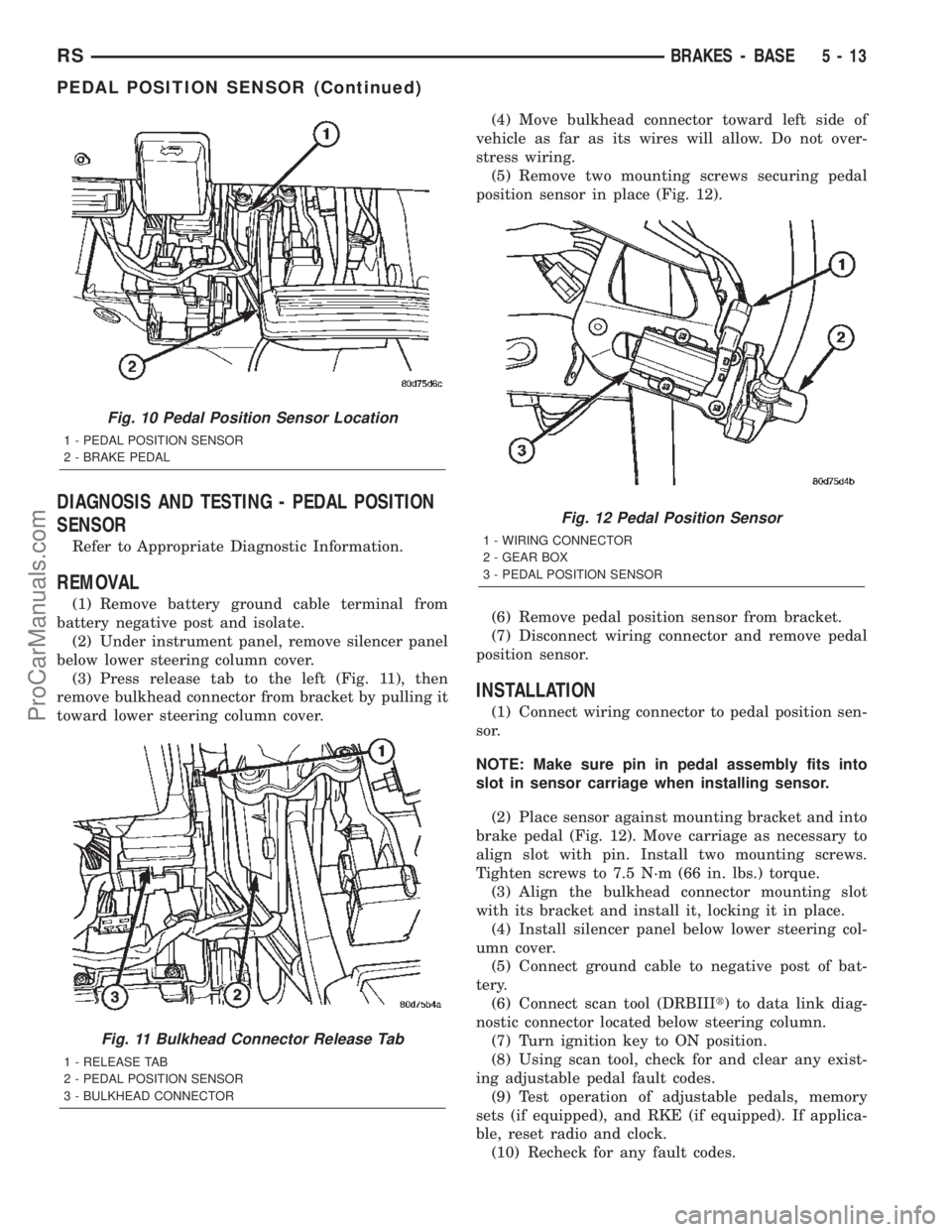
(3) Press release tab to the left (Fig. 11), then
remove bulkhead connector from bracket by pulling it
toward lower steering column cover.(4) Move bulkhead connector toward left side of
vehicle as far as its wires will allow. Do not over-
stress wiring.
(5) Remove two mounting screws securing pedal
position sensor in place (Fig. 12).
(6) Remove pedal position sensor from bracket.
(7) Disconnect wiring connector and remove pedal
position sensor.
INSTALLATION
(1) Connect wiring connector to pedal position sen-
sor.
NOTE: Make sure pin in pedal assembly fits into
slot in sensor carriage when installing sensor.
(2) Place sensor against mounting bracket and into
brake pedal (Fig. 12). Move carriage as necessary to
align slot with pin. Install two mounting screws.
Tighten screws to 7.5 N´m (66 in. lbs.) torque.
(3) Align the bulkhead connector mounting slot
with its bracket and install it, locking it in place.
(4) Install silencer panel below lower steering col-
umn cover.
(5) Connect ground cable to negative post of bat-
tery.
(6) Connect scan tool (DRBIIIt) to data link diag-
nostic connector located below steering column.
(7) Turn ignition key to ON position.
(8) Using scan tool, check for and clear any exist-
ing adjustable pedal fault codes.
(9) Test operation of adjustable pedals, memory
sets (if equipped), and RKE (if equipped). If applica-
ble, reset radio and clock.
(10) Recheck for any fault codes.
Fig. 10 Pedal Position Sensor Location
1 - PEDAL POSITION SENSOR
2 - BRAKE PEDAL
Fig. 11 Bulkhead Connector Release Tab
1 - RELEASE TAB
2 - PEDAL POSITION SENSOR
3 - BULKHEAD CONNECTOR
Fig. 12 Pedal Position Sensor
1 - WIRING CONNECTOR
2 - GEAR BOX
3 - PEDAL POSITION SENSOR
RSBRAKES - BASE5-13
PEDAL POSITION SENSOR (Continued)
ProCarManuals.com
Page 165 of 2399
CAUTION: Never use any type of a petroleum-based
fluid in the brake hydraulic system. Use of such
type fluids will result in seal damage of the vehicle
brake hydraulic system causing a failure of the
vehicle brake system. Petroleum based fluids would
be items such as engine oil, transmission fluid,
power steering fluid, etc.
JUNCTION BLOCK
DESCRIPTION - NON-ABS JUNCTION BLOCK
A junction block is used on vehicles that are not
equipped with antilock brakes (ABS). The junction
block mounts in the same location as the integrated
control unit (ICU) does on vehicles equipped with
ABS. This allows for use of the same brake tube con-
figuration on all vehicles. The junction block is
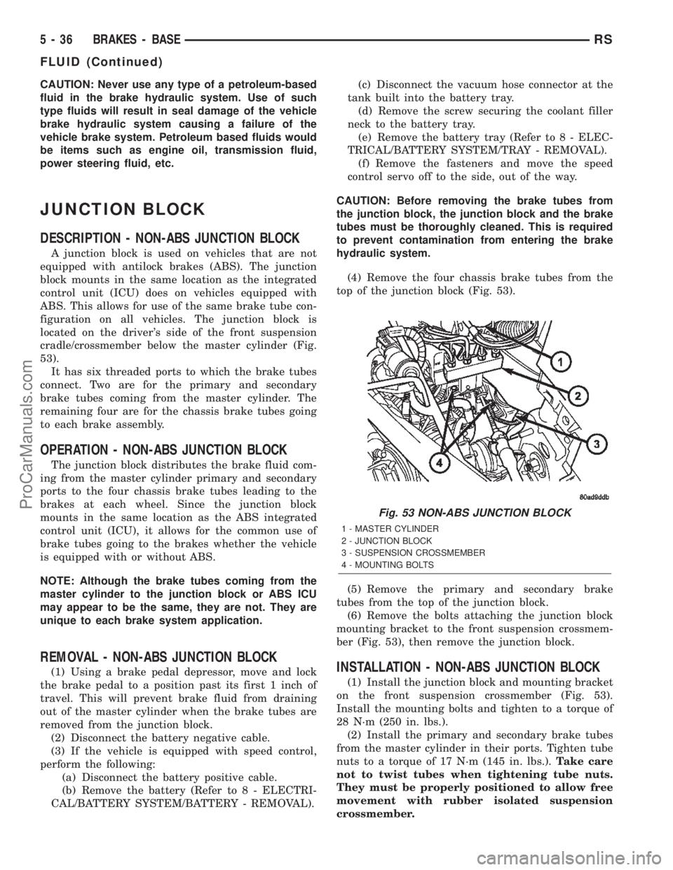
located on the driver's side of the front suspension
cradle/crossmember below the master cylinder (Fig.
53).
It has six threaded ports to which the brake tubes
connect. Two are for the primary and secondary
brake tubes coming from the master cylinder. The
remaining four are for the chassis brake tubes going
to each brake assembly.
OPERATION - NON-ABS JUNCTION BLOCK
The junction block distributes the brake fluid com-
ing from the master cylinder primary and secondary
ports to the four chassis brake tubes leading to the
brakes at each wheel. Since the junction block
mounts in the same location as the ABS integrated
control unit (ICU), it allows for the common use of
brake tubes going to the brakes whether the vehicle
is equipped with or without ABS.
NOTE: Although the brake tubes coming from the
master cylinder to the junction block or ABS ICU
may appear to be the same, they are not. They are
unique to each brake system application.
REMOVAL - NON-ABS JUNCTION BLOCK
(1) Using a brake pedal depressor, move and lock
the brake pedal to a position past its first 1 inch of
travel. This will prevent brake fluid from draining
out of the master cylinder when the brake tubes are
removed from the junction block.
(2) Disconnect the battery negative cable.
(3) If the vehicle is equipped with speed control,
perform the following:
(a) Disconnect the battery positive cable.
(b) Remove the battery (Refer to 8 - ELECTRI-
CAL/BATTERY SYSTEM/BATTERY - REMOVAL).(c) Disconnect the vacuum hose connector at the
tank built into the battery tray.
(d) Remove the screw securing the coolant filler
neck to the battery tray.
(e) Remove the battery tray (Refer to 8 - ELEC-
TRICAL/BATTERY SYSTEM/TRAY - REMOVAL).
(f) Remove the fasteners and move the speed
control servo off to the side, out of the way.
CAUTION: Before removing the brake tubes from
the junction block, the junction block and the brake
tubes must be thoroughly cleaned. This is required
to prevent contamination from entering the brake
hydraulic system.
(4) Remove the four chassis brake tubes from the
top of the junction block (Fig. 53).
(5) Remove the primary and secondary brake
tubes from the top of the junction block.
(6) Remove the bolts attaching the junction block
mounting bracket to the front suspension crossmem-
ber (Fig. 53), then remove the junction block.INSTALLATION - NON-ABS JUNCTION BLOCK
(1) Install the junction block and mounting bracket
on the front suspension crossmember (Fig. 53).
Install the mounting bolts and tighten to a torque of
28 N´m (250 in. lbs.).
(2) Install the primary and secondary brake tubes
from the master cylinder in their ports. Tighten tube
nuts to a torque of 17 N´m (145 in. lbs.).Take care
not to twist tubes when tightening tube nuts.
They must be properly positioned to allow free
movement with rubber isolated suspension
crossmember.
Fig. 53 NON-ABS JUNCTION BLOCK
1 - MASTER CYLINDER
2 - JUNCTION BLOCK
3 - SUSPENSION CROSSMEMBER
4 - MOUNTING BOLTS
5 - 36 BRAKES - BASERS
FLUID (Continued)
ProCarManuals.com