fig. 78 CHRYSLER CARAVAN 2002 User Guide
[x] Cancel search | Manufacturer: CHRYSLER, Model Year: 2002, Model line: CARAVAN, Model: CHRYSLER CARAVAN 2002Pages: 2399, PDF Size: 57.96 MB
Page 15 of 2399
INTERNATIONAL SYMBOLS
DESCRIPTION
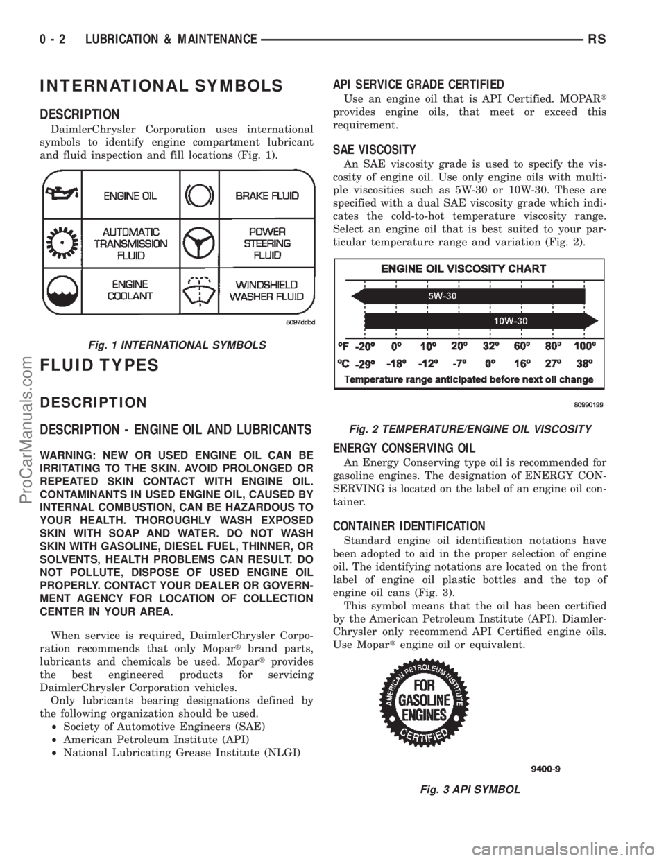
DaimlerChrysler Corporation uses international
symbols to identify engine compartment lubricant
and fluid inspection and fill locations (Fig. 1).
FLUID TYPES
DESCRIPTION
DESCRIPTION - ENGINE OIL AND LUBRICANTS
WARNING: NEW OR USED ENGINE OIL CAN BE
IRRITATING TO THE SKIN. AVOID PROLONGED OR
REPEATED SKIN CONTACT WITH ENGINE OIL.
CONTAMINANTS IN USED ENGINE OIL, CAUSED BY
INTERNAL COMBUSTION, CAN BE HAZARDOUS TO
YOUR HEALTH. THOROUGHLY WASH EXPOSED
SKIN WITH SOAP AND WATER. DO NOT WASH
SKIN WITH GASOLINE, DIESEL FUEL, THINNER, OR
SOLVENTS, HEALTH PROBLEMS CAN RESULT. DO
NOT POLLUTE, DISPOSE OF USED ENGINE OIL
PROPERLY. CONTACT YOUR DEALER OR GOVERN-
MENT AGENCY FOR LOCATION OF COLLECTION
CENTER IN YOUR AREA.
When service is required, DaimlerChrysler Corpo-
ration recommends that only Mopartbrand parts,
lubricants and chemicals be used. Mopartprovides
the best engineered products for servicing
DaimlerChrysler Corporation vehicles.
Only lubricants bearing designations defined by
the following organization should be used.
²Society of Automotive Engineers (SAE)
²American Petroleum Institute (API)
²National Lubricating Grease Institute (NLGI)
API SERVICE GRADE CERTIFIED
Use an engine oil that is API Certified. MOPARt
provides engine oils, that meet or exceed this
requirement.
SAE VISCOSITY
An SAE viscosity grade is used to specify the vis-
cosity of engine oil. Use only engine oils with multi-
ple viscosities such as 5W-30 or 10W-30. These are
specified with a dual SAE viscosity grade which indi-
cates the cold-to-hot temperature viscosity range.
Select an engine oil that is best suited to your par-
ticular temperature range and variation (Fig. 2).
ENERGY CONSERVING OIL
An Energy Conserving type oil is recommended for
gasoline engines. The designation of ENERGY CON-
SERVING is located on the label of an engine oil con-
tainer.
CONTAINER IDENTIFICATION
Standard engine oil identification notations have
been adopted to aid in the proper selection of engine
oil. The identifying notations are located on the front
label of engine oil plastic bottles and the top of
engine oil cans (Fig. 3).
This symbol means that the oil has been certified
by the American Petroleum Institute (API). Diamler-
Chrysler only recommend API Certified engine oils.
Use Mopartengine oil or equivalent.
Fig. 1 INTERNATIONAL SYMBOLS
Fig. 2 TEMPERATURE/ENGINE OIL VISCOSITY
Fig. 3 API SYMBOL
0 - 2 LUBRICATION & MAINTENANCERS
ProCarManuals.com
Page 16 of 2399
GEAR LUBRICANTS
SAE ratings also apply to multigrade gear lubri-
cants. In addition, API classification defines the
lubricants usage. Such as API GL-5 and SAE 75W-
90.
LUBRICANTS AND GREASES
Lubricating grease is rated for quality and usage
by the NLGI. All approved products have the NLGI
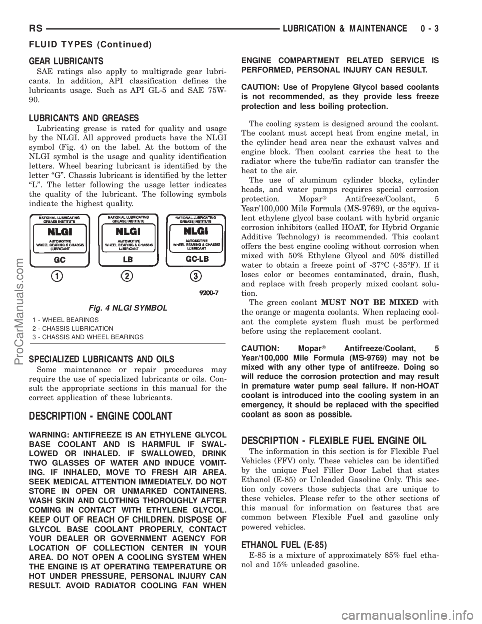
symbol (Fig. 4) on the label. At the bottom of the
NLGI symbol is the usage and quality identification
letters. Wheel bearing lubricant is identified by the
letter ªGº. Chassis lubricant is identified by the letter
ªLº. The letter following the usage letter indicates
the quality of the lubricant. The following symbols
indicate the highest quality.
SPECIALIZED LUBRICANTS AND OILS
Some maintenance or repair procedures may
require the use of specialized lubricants or oils. Con-
sult the appropriate sections in this manual for the
correct application of these lubricants.
DESCRIPTION - ENGINE COOLANT
WARNING: ANTIFREEZE IS AN ETHYLENE GLYCOL
BASE COOLANT AND IS HARMFUL IF SWAL-
LOWED OR INHALED. IF SWALLOWED, DRINK
TWO GLASSES OF WATER AND INDUCE VOMIT-
ING. IF INHALED, MOVE TO FRESH AIR AREA.
SEEK MEDICAL ATTENTION IMMEDIATELY. DO NOT
STORE IN OPEN OR UNMARKED CONTAINERS.
WASH SKIN AND CLOTHING THOROUGHLY AFTER
COMING IN CONTACT WITH ETHYLENE GLYCOL.
KEEP OUT OF REACH OF CHILDREN. DISPOSE OF
GLYCOL BASE COOLANT PROPERLY, CONTACT
YOUR DEALER OR GOVERNMENT AGENCY FOR
LOCATION OF COLLECTION CENTER IN YOUR
AREA. DO NOT OPEN A COOLING SYSTEM WHEN
THE ENGINE IS AT OPERATING TEMPERATURE OR
HOT UNDER PRESSURE, PERSONAL INJURY CAN
RESULT. AVOID RADIATOR COOLING FAN WHENENGINE COMPARTMENT RELATED SERVICE IS
PERFORMED, PERSONAL INJURY CAN RESULT.
CAUTION: Use of Propylene Glycol based coolants
is not recommended, as they provide less freeze
protection and less boiling protection.
The cooling system is designed around the coolant.
The coolant must accept heat from engine metal, in
the cylinder head area near the exhaust valves and
engine block. Then coolant carries the heat to the
radiator where the tube/fin radiator can transfer the
heat to the air.
The use of aluminum cylinder blocks, cylinder
heads, and water pumps requires special corrosion
protection. MopartAntifreeze/Coolant, 5
Year/100,000 Mile Formula (MS-9769), or the equiva-
lent ethylene glycol base coolant with hybrid organic
corrosion inhibitors (called HOAT, for Hybrid Organic
Additive Technology) is recommended. This coolant
offers the best engine cooling without corrosion when
mixed with 50% Ethylene Glycol and 50% distilled
water to obtain a freeze point of -37ÉC (-35ÉF). If it
loses color or becomes contaminated, drain, flush,
and replace with fresh properly mixed coolant solu-
tion.
The green coolantMUST NOT BE MIXEDwith
the orange or magenta coolants. When replacing cool-
ant the complete system flush must be performed
before using the replacement coolant.
CAUTION: MoparTAntifreeze/Coolant, 5
Year/100,000 Mile Formula (MS-9769) may not be
mixed with any other type of antifreeze. Doing so
will reduce the corrosion protection and may result
in premature water pump seal failure. If non-HOAT
coolant is introduced into the cooling system in an
emergency, it should be replaced with the specified
coolant as soon as possible.DESCRIPTION - FLEXIBLE FUEL ENGINE OIL
The information in this section is for Flexible Fuel
Vehicles (FFV) only. These vehicles can be identified
by the unique Fuel Filler Door Label that states
Ethanol (E-85) or Unleaded Gasoline Only. This sec-
tion only covers those subjects that are unique to
these vehicles. Please refer to the other sections of
this manual for information on features that are
common between Flexible Fuel and gasoline only
powered vehicles.
ETHANOL FUEL (E-85)
E-85 is a mixture of approximately 85% fuel etha-
nol and 15% unleaded gasoline.
Fig. 4 NLGI SYMBOL
1 - WHEEL BEARINGS
2 - CHASSIS LUBRICATION
3 - CHASSIS AND WHEEL BEARINGS
RSLUBRICATION & MAINTENANCE0-3
FLUID TYPES (Continued)
ProCarManuals.com
Page 19 of 2399
²The use of fuel additives which are now being
sold as octane enhancers is not recommended. Most
of these products contain high concentrations of
methanol. Fuel system damage or vehicle perfor-
mance problems resulting from the use of such fuels
or additives is not the responsibility of
DaimlerChrysler Corporation and may not be covered
under the new vehicle warranty.
NOTE: Intentional tampering with emissions control
systems can result in civil penalties being assessed
against you.
DESCRIPTION - FUEL REQUIREMENTS -
DIESEL ENGINE
WARNING: DO NOT USE ALCOHOL OR GASOLINE
AS A FUEL BLENDING AGENT. THEY CAN BE
UNSTABLE UNDER CERTAIN CONDITIONS AND
HAZARDOUS OR EXPLOSIVE WHEN MIXED WITH
DIESEL FUEL.
Use good quality diesel fuel from a reputable sup-
plier. For most year-round service, number 2 diesel
fuel meeting ASTM specification D-975 will provide
good performance. If the vehicle is exposed to
extreme cold (below -18ÉC/0ÉF) or is required to oper-
ate at colder than normal conditions for prolonged
periods, use climatize No. 2 diesel fuel or dilute the
No. 2 diesel fuel with 50% No. 1 diesel fuel. This will
provide better protection from fuel gelling or wax
plugging of the fuel filters.
Diesel fuel is seldom completely free of water. To
prevent fuel system trouble, including fuel line freez-
ing in winter, drain the accumulated water from the
fuel/water separator using the fuel/water separator
drain provided. If you buy good quality fuel and fol-
low the cold weather advice above, fuel conditioners
should not be required in your vehicle. If available in
your area, a high cetane ªpremiumº diesel fuel may
offer improved cold starting and warm up perfor-
mance.
DESCRIPTION - ENGINE OIL - DIESEL
ENGINES
Use only Diesel Engine Oil meeting standardMIL-
2104Cor API ClassificationCD or higherorCCML
D4, D5.
SAE VISCOSITY GRADE
CAUTION: Low viscosity oils must have the proper
API quality or the CCMC G5 designation.
To assure of properly formulated engine oils, it is
recommended that SAE Grade 10W-40 engine oilsthat meet Chrysler material standard MS-6395, be
used. European Grade 10W-40 oils are also accept-
able.
Oils of the SAE 5W-40 or 8W-80 grade number are
preferred when minimum temperatures consistently
fall below -12ÉC.
FLUID FILL/CHECK
LOCATIONS
DESCRIPTION
The fluid check/fill point locations are located in
each applicable service manual section.
LUBRICATION POINTS
DESCRIPTION
Lubrication point locations are located in each
applicable Sections.
MAINTENANCE SCHEDULES
DESCRIPTION
9Maintenance Schedule Information not included in
this section, is located in the appropriate Owner's
Manual.9
HOISTING
STANDARD PROCEDURE - HOISTING
Refer to Owner's Manual provided with vehicle for
proper emergency jacking procedures.
WARNING: THE HOISTING AND JACK LIFTING
POINTS PROVIDED ARE FOR A COMPLETE VEHI-
CLE. WHEN THE ENGINE OR REAR SUSPENSION
IS REMOVED FROM A VEHICLE, THE CENTER OF
GRAVITY IS ALTERED MAKING SOME HOISTING
CONDITIONS UNSTABLE. PROPERLY SUPPORT OR
SECURE VEHICLE TO HOISTING DEVICE WHEN
THESE CONDITIONS EXIST.
CAUTION: Do not position hoisting device on any
suspension component, including the front suspen-
sion crossmember, the rear leaf springs, and the
rear axle. Do not hoist on the front and rear
bumpers, the lower liftgate crossmember, the lower
radiator crossmember, the down standing flanges
on the sill or the front engine mount.
FOR PROPER HOIST PLACEMENT REFER
TO (Fig. 5).
0 - 6 LUBRICATION & MAINTENANCERS
FLUID TYPES (Continued)
ProCarManuals.com
Page 20 of 2399
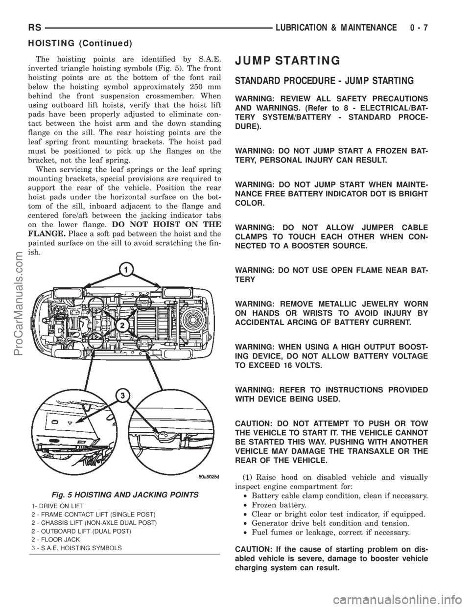
The hoisting points are identified by S.A.E.
inverted triangle hoisting symbols (Fig. 5). The front
hoisting points are at the bottom of the font rail
below the hoisting symbol approximately 250 mm
behind the front suspension crossmember. When
using outboard lift hoists, verify that the hoist lift
pads have been properly adjusted to eliminate con-
tact between the hoist arm and the down standing
flange on the sill. The rear hoisting points are the
leaf spring front mounting brackets. The hoist pad
must be positioned to pick up the flanges on the
bracket, not the leaf spring.
When servicing the leaf springs or the leaf spring
mounting brackets, special provisions are required to
support the rear of the vehicle. Position the rear
hoist pads under the horizontal surface on the bot-
tom of the sill, inboard adjacent to the flange and
centered fore/aft between the jacking indicator tabs
on the lower flange.DO NOT HOIST ON THE
FLANGE.Place a soft pad between the hoist and the
painted surface on the sill to avoid scratching the fin-
ish.JUMP STARTING
STANDARD PROCEDURE - JUMP STARTING
WARNING: REVIEW ALL SAFETY PRECAUTIONS
AND WARNINGS. (Refer to 8 - ELECTRICAL/BAT-
TERY SYSTEM/BATTERY - STANDARD PROCE-
DURE).
WARNING: DO NOT JUMP START A FROZEN BAT-
TERY, PERSONAL INJURY CAN RESULT.
WARNING: DO NOT JUMP START WHEN MAINTE-
NANCE FREE BATTERY INDICATOR DOT IS BRIGHT
COLOR.
WARNING: DO NOT ALLOW JUMPER CABLE
CLAMPS TO TOUCH EACH OTHER WHEN CON-
NECTED TO A BOOSTER SOURCE.
WARNING: DO NOT USE OPEN FLAME NEAR BAT-
TERY
WARNING: REMOVE METALLIC JEWELRY WORN
ON HANDS OR WRISTS TO AVOID INJURY BY
ACCIDENTAL ARCING OF BATTERY CURRENT.
WARNING: WHEN USING A HIGH OUTPUT BOOST-
ING DEVICE, DO NOT ALLOW BATTERY VOLTAGE
TO EXCEED 16 VOLTS.
WARNING: REFER TO INSTRUCTIONS PROVIDED
WITH DEVICE BEING USED.
CAUTION: DO NOT ATTEMPT TO PUSH OR TOW
THE VEHICLE TO START IT. THE VEHICLE CANNOT
BE STARTED THIS WAY. PUSHING WITH ANOTHER
VEHICLE MAY DAMAGE THE TRANSAXLE OR THE
REAR OF THE VEHICLE.
(1) Raise hood on disabled vehicle and visually
inspect engine compartment for:
²Battery cable clamp condition, clean if necessary.
²Frozen battery.
²Clear or bright color test indicator, if equipped.
²Generator drive belt condition and tension.
²Fuel fumes or leakage, correct if necessary.
CAUTION: If the cause of starting problem on dis-
abled vehicle is severe, damage to booster vehicle
charging system can result.
Fig. 5 HOISTING AND JACKING POINTS
1- DRIVE ON LIFT
2 - FRAME CONTACT LIFT (SINGLE POST)
2 - CHASSIS LIFT (NON-AXLE DUAL POST)
2 - OUTBOARD LIFT (DUAL POST)
2 - FLOOR JACK
3 - S.A.E. HOISTING SYMBOLS
RSLUBRICATION & MAINTENANCE0-7
HOISTING (Continued)
ProCarManuals.com
Page 21 of 2399

(2) When using another vehicle as a booster
source, park the booster vehicle within cable reach.
Turn off all accessories, set the parking brake, place
the automatic transmission in PARK or the manual
transmission in NEUTRAL and turn the ignition
OFF.
(3) On disabled vehicle, place gear selector in park
or neutral and set park brake. Turn off all accesso-
ries.
(4) Connect jumper cables to booster battery. RED
clamp to positive terminal (+). BLACK clamp to neg-
ative terminal (-). DO NOT allow clamps at opposite
end of cables to touch, electrical arc will result.
Review all warnings in this procedure.
(5) On disabled vehicle, connect RED jumper cable
clamp to positive (+) terminal. Connect BLACK
jumper cable clamp to engine ground as close to the
ground cable attaching point as possible (Fig. 6).
(Refer to 8 - ELECTRICAL/BATTERY SYSTEM/BAT-
TERY - STANDARD PROCEDURE).
(6) Start the engine in the vehicle which has the
booster battery, let the engine idle a few minutes,
then start the engine in the vehicle with the dis-
charged battery.
CAUTION: Do not crank starter motor on disabled
vehicle for more than 15 seconds, starter may over-
heat and could fail.
(7) If engine does not start within 15 seconds, stop
cranking engine and allow starter to cool (15 min-
utes), before cranking again.DISCONNECT CABLE CLAMPS AS FOLLOWS:
²Disconnect BLACK cable clamp from engine
ground on disabled vehicle.
²When using a Booster vehicle, disconnect
BLACK cable clamp from battery negative terminal.
Disconnect RED cable clamp from battery positive
terminal.
²Disconnect RED cable clamp from battery posi-
tive terminal on disabled vehicle.
TOWING
STANDARD PROCEDURE - TOWING
WARNINGS AND CAUTIONS
WARNING: DO NOT ALLOW TOWING ATTACHMENT
DEVICES TO CONTACT THE FUEL TANK OR LINES,
FUEL LEAK CAN RESULT.
DO NOT LIFT OR TOW VEHICLE BY FRONT OR
REAR BUMPER.
DO NOT GO UNDER A LIFTED VEHICLE IF NOT
SUPPORTED PROPERLY ON SAFETY STANDS.
DO NOT ALLOW PASSENGERS TO RIDE IN A
TOWED VEHICLE.
USE A SAFETY CHAIN THAT IS INDEPENDENT
FROM THE TOWING ATTACHMENT DEVICE.
CAUTION: Do not damage brake lines, exhaust sys-
tem, shock absorbers, sway bars, or any other
under vehicle components when attaching towing
device to vehicle.
Do not secure vehicle to towing device by the use
of front or rear suspension or steering components.
Remove or secure loose or protruding objects from
a damaged vehicle before towing.
Refer to state and local rules and regulations before
towing a vehicle.
Do not allow weight of towed vehicle to bear on
lower fascia, air dams, or spoilers.
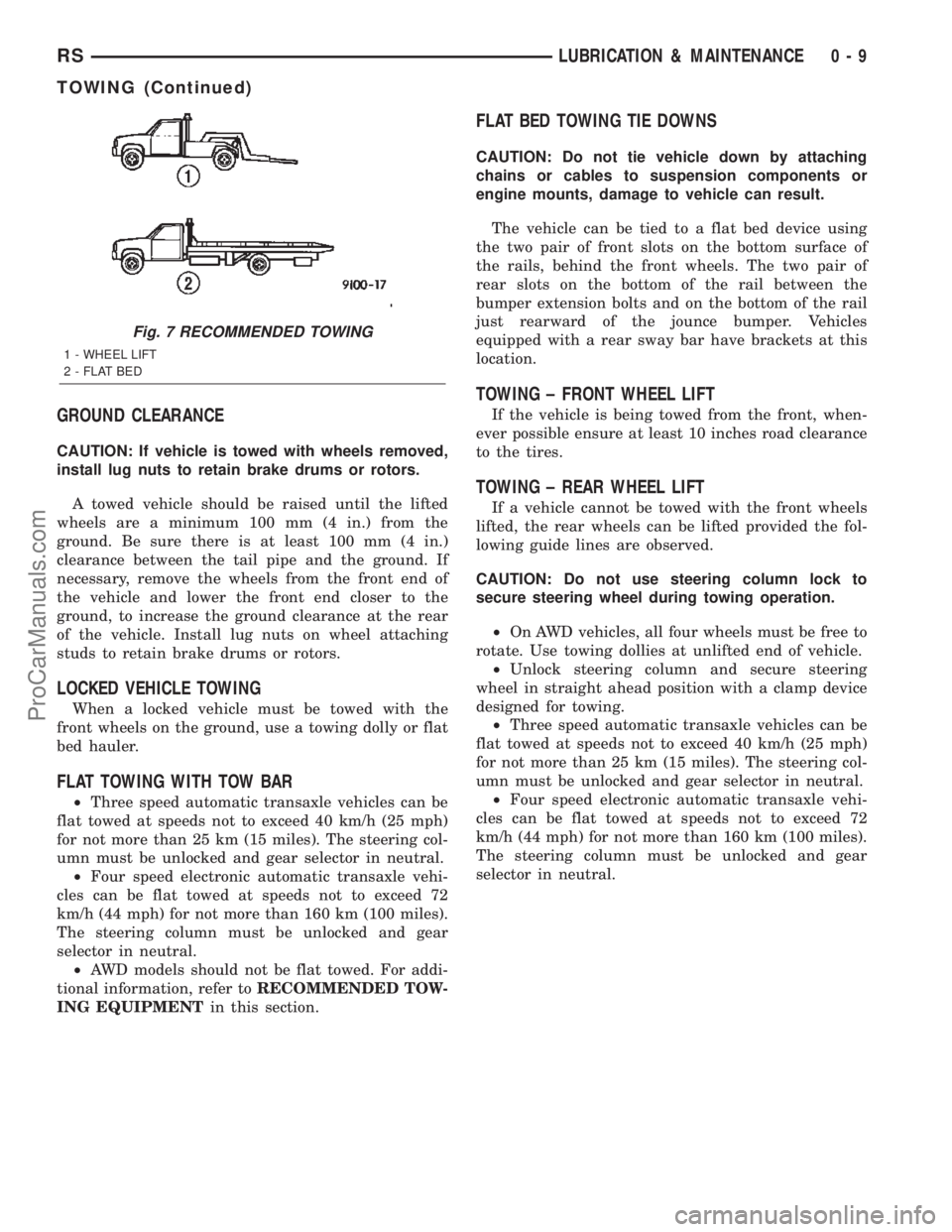
RECOMMENDED TOWING EQUIPMENT
To avoid damage to bumper fascia and air dams
use:
²FWD vehicles, use of a flat bed towing device or
a wheel lift is recommended (Fig. 7).
²AWD vehicles, a flat bed towing device or a
wheel lift and towing dolly is recommended (Fig. 7).
When using a wheel lift towing device, be sure the
disabled vehicle has at least 100 mm (4 in.) ground
clearance. If minimum ground clearance cannot be
reached, use a towing dolly. If a flat bed device is
used, the approach angle should not exceed 15
degrees.
Fig. 6 JUMPER CABLE CLAMP CONNECTIONS
1 - BATTERY NEGATIVE TERMINAL
2 - POSITIVE JUMPER CABLE
3 - TEST INDICATOR (IF EQUIPPED)
4 - BATTERY POSITIVE TERMINAL
5 - BATTERY
6 - NEGATIVE JUMPER CABLE
0 - 8 LUBRICATION & MAINTENANCERS
JUMP STARTING (Continued)
ProCarManuals.com
Page 22 of 2399
GROUND CLEARANCE
CAUTION: If vehicle is towed with wheels removed,
install lug nuts to retain brake drums or rotors.
A towed vehicle should be raised until the lifted
wheels are a minimum 100 mm (4 in.) from the
ground. Be sure there is at least 100 mm (4 in.)
clearance between the tail pipe and the ground. If
necessary, remove the wheels from the front end of
the vehicle and lower the front end closer to the
ground, to increase the ground clearance at the rear
of the vehicle. Install lug nuts on wheel attaching
studs to retain brake drums or rotors.
LOCKED VEHICLE TOWING
When a locked vehicle must be towed with the
front wheels on the ground, use a towing dolly or flat
bed hauler.
FLAT TOWING WITH TOW BAR
²Three speed automatic transaxle vehicles can be
flat towed at speeds not to exceed 40 km/h (25 mph)
for not more than 25 km (15 miles). The steering col-
umn must be unlocked and gear selector in neutral.
²Four speed electronic automatic transaxle vehi-
cles can be flat towed at speeds not to exceed 72
km/h (44 mph) for not more than 160 km (100 miles).
The steering column must be unlocked and gear
selector in neutral.
²AWD models should not be flat towed. For addi-
tional information, refer toRECOMMENDED TOW-
ING EQUIPMENTin this section.
FLAT BED TOWING TIE DOWNS
CAUTION: Do not tie vehicle down by attaching
chains or cables to suspension components or
engine mounts, damage to vehicle can result.
The vehicle can be tied to a flat bed device using
the two pair of front slots on the bottom surface of
the rails, behind the front wheels. The two pair of
rear slots on the bottom of the rail between the
bumper extension bolts and on the bottom of the rail
just rearward of the jounce bumper. Vehicles
equipped with a rear sway bar have brackets at this
location.
TOWING ± FRONT WHEEL LIFT
If the vehicle is being towed from the front, when-
ever possible ensure at least 10 inches road clearance
to the tires.
TOWING ± REAR WHEEL LIFT
If a vehicle cannot be towed with the front wheels
lifted, the rear wheels can be lifted provided the fol-
lowing guide lines are observed.
CAUTION: Do not use steering column lock to
secure steering wheel during towing operation.
²On AWD vehicles, all four wheels must be free to
rotate. Use towing dollies at unlifted end of vehicle.
²Unlock steering column and secure steering
wheel in straight ahead position with a clamp device
designed for towing.
²Three speed automatic transaxle vehicles can be
flat towed at speeds not to exceed 40 km/h (25 mph)
for not more than 25 km (15 miles). The steering col-
umn must be unlocked and gear selector in neutral.
²Four speed electronic automatic transaxle vehi-
cles can be flat towed at speeds not to exceed 72
km/h (44 mph) for not more than 160 km (100 miles).
The steering column must be unlocked and gear
selector in neutral.
Fig. 7 RECOMMENDED TOWING
1 - WHEEL LIFT
2 - FLAT BED
RSLUBRICATION & MAINTENANCE0-9
TOWING (Continued)
ProCarManuals.com
Page 25 of 2399

FRONT SUSPENSION
DESCRIPTION - FRONT SUSPENSION
This vehicle has a MacPherson Strut type front
suspension (Fig. 1).
OPERATION - FRONT SUSPENSION
The front suspension allows each wheel on a vehi-
cle to adapt to different road surfaces and conditions
without greatly affecting the opposite wheel and the
ability to control the vehicle. Each side of the front
suspension is allowed to pivot so the vehicle can be
steered in the direction preferred.
A strut assembly is used in place of the front sus-
pension upper control arm and upper ball joint.
When a vehicle strikes a bump, the force is trans-
ferred through the hub, bearing, and knuckle, into
the strut assembly to absorb the force and dampen it.
The top of the strut is mounted directly to the strut
tower of the vehicle. During steering maneuvers, thestrut assembly (through a pivot bearing in the upper
strut mount) and steering knuckle (through the lower
ball joint) turn as an assembly.
STANDARD PROCEDURE - LUBRICATION
There are no serviceable lubrication points on the
front suspension. The ball joints are sealed-for-life
and require no maintenance. The lower ball joints
have special grease fitting caps that prevent normal
grease gun attachment. This has been done to elimi-
nate the possibility of over-filling, damaging the non-
vented seal. Do not attempt to remove the special
grease fitting cap and replace it with a normal grease
zirc fitting.
CAUTION: No attempt should be made to replace
the ball joint grease fitting cap with a normal zirc
fitting or fill the ball joint with grease. Damage to
the grease seal can result.
Fig. 1 Front Suspension
1 - TOWER
2 - CROSSMEMBER TAPPING PLATES
3 - LEFT STRUT ASSEMBLY
4 - LEFT STEERING KNUCKLE (WITH HUB AND BEARING)
5 - STABILIZER BAR LINK
6 - STABILIZER BAR
7 - LEFT LOWER CONTROL ARM
8 - CRADLE/CROSSMEMBER9 - CRADLE/CROSSMEMBER REINFORCEMENT
10 - BALL JOINT
11 - ISOLATOR BUSHING
12 - STEERING GEAR TIE ROD
13 - RIGHT STEERING KNUCKLE
14 - RIGHT HUB AND BEARING
15 - RIGHT STRUT ASSEMBLY
2 - 2 FRONT SUSPENSIONRS
ProCarManuals.com
Page 27 of 2399
BUSHINGS
REMOVAL - STABILIZER BAR CUSHION
(1) Raise Vehicle. Refer to Hoisting in Lubrication
and Maintenance.
(2) Remove the 2 bolts fastening the emission leak
detection pump to the cradle crossmember reinforce-
ment.
(3) Move the leak detection pump to the side
allowing access to the stabilizer bar cushion retain-
ers.
(4) Remove the nut and bolt securing each stabi-
lizer bar cushion retainer to the cradle crossmember
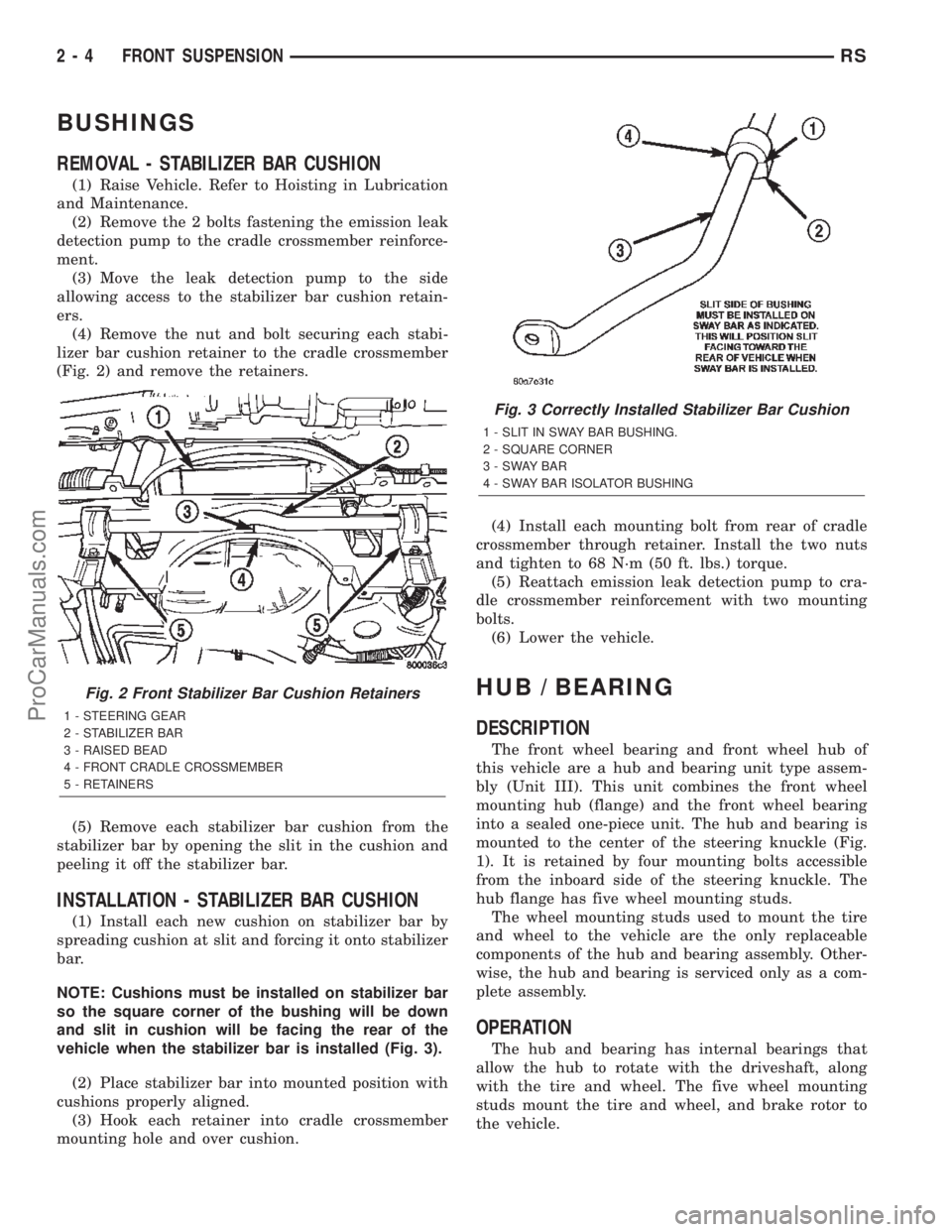
(Fig. 2) and remove the retainers.
(5) Remove each stabilizer bar cushion from the
stabilizer bar by opening the slit in the cushion and
peeling it off the stabilizer bar.
INSTALLATION - STABILIZER BAR CUSHION
(1) Install each new cushion on stabilizer bar by
spreading cushion at slit and forcing it onto stabilizer
bar.
NOTE: Cushions must be installed on stabilizer bar
so the square corner of the bushing will be down
and slit in cushion will be facing the rear of the
vehicle when the stabilizer bar is installed (Fig. 3).
(2) Place stabilizer bar into mounted position with
cushions properly aligned.
(3) Hook each retainer into cradle crossmember
mounting hole and over cushion.(4) Install each mounting bolt from rear of cradle
crossmember through retainer. Install the two nuts
and tighten to 68 N´m (50 ft. lbs.) torque.
(5) Reattach emission leak detection pump to cra-
dle crossmember reinforcement with two mounting
bolts.
(6) Lower the vehicle.
HUB / BEARING
DESCRIPTION
The front wheel bearing and front wheel hub of
this vehicle are a hub and bearing unit type assem-
bly (Unit III). This unit combines the front wheel
mounting hub (flange) and the front wheel bearing
into a sealed one-piece unit. The hub and bearing is
mounted to the center of the steering knuckle (Fig.
1). It is retained by four mounting bolts accessible
from the inboard side of the steering knuckle. The
hub flange has five wheel mounting studs.
The wheel mounting studs used to mount the tire
and wheel to the vehicle are the only replaceable
components of the hub and bearing assembly. Other-
wise, the hub and bearing is serviced only as a com-
plete assembly.
OPERATION
The hub and bearing has internal bearings that
allow the hub to rotate with the driveshaft, along
with the tire and wheel. The five wheel mounting
studs mount the tire and wheel, and brake rotor to
the vehicle.
Fig. 2 Front Stabilizer Bar Cushion Retainers
1 - STEERING GEAR
2 - STABILIZER BAR
3 - RAISED BEAD
4 - FRONT CRADLE CROSSMEMBER
5 - RETAINERS
Fig. 3 Correctly Installed Stabilizer Bar Cushion
1 - SLIT IN SWAY BAR BUSHING.
2 - SQUARE CORNER
3-SWAYBAR
4 - SWAY BAR ISOLATOR BUSHING
2 - 4 FRONT SUSPENSIONRS
ProCarManuals.com
Page 28 of 2399
DIAGNOSIS AND TESTING - HUB AND
BEARING
The condition of the front hub and bearing assem-
bly is diagnosed using the inspection and testing pro-
cedure detailed below.
The bearing contained in the Unit III front hub/
bearing assembly will produce noise and vibration
when worn or damaged. The noise will generally
change when the bearings are loaded. A road test of
the vehicle is normally required to determine the
location of a worn or damaged bearing.
Find a smooth level road surface and bring the
vehicle up to a constant speed. When vehicle is at a
constant speed, swerve the vehicle back and forth
from the left and to the right. This will load and
unload the bearings and change the noise level.
When bearing damage is slight, the noise is some-
times noticeable at lower speeds and at other times
is more noticeable at speeds above 105 km/h (65
mph).
REMOVAL
NOTE: Replacement of the Unit III front hub/bearing
assembly can be normally done without having to
remove the steering knuckle from the vehicle. In the
event that the hub/bearing is frozen in the steering
knuckle and cannot be removed by hand, it will
have to be pressed out of the steering knuckle. The
steering knuckle will require removal from the vehi-
cle to allow the hub/bearing assembly to be
pressed out of the steering knuckle. (Refer to 2 -
SUSPENSION/FRONT/KNUCKLE - REMOVAL)
(1) Raise vehicle. (Refer to LUBRICATION &
MAINTENANCE/HOISTING - STANDARD PROCE-
DURE)
(2) Remove wheel lug nuts, and front tire and
wheel assembly.
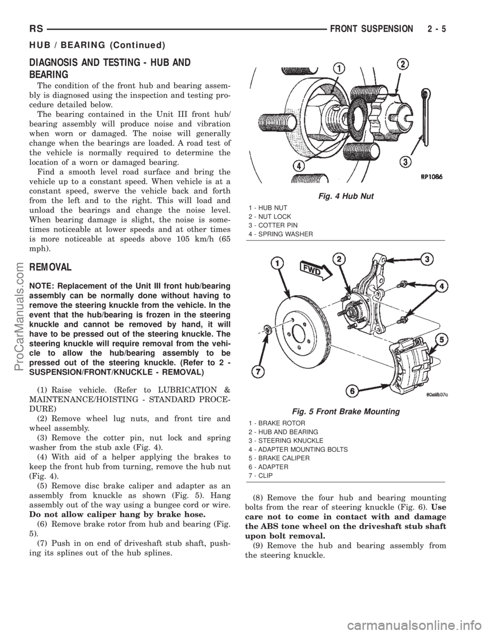
(3) Remove the cotter pin, nut lock and spring
washer from the stub axle (Fig. 4).
(4) With aid of a helper applying the brakes to
keep the front hub from turning, remove the hub nut
(Fig. 4).
(5) Remove disc brake caliper and adapter as an
assembly from knuckle as shown (Fig. 5). Hang
assembly out of the way using a bungee cord or wire.
Do not allow caliper hang by brake hose.
(6) Remove brake rotor from hub and bearing (Fig.
5).
(7) Push in on end of driveshaft stub shaft, push-
ing its splines out of the hub splines.(8) Remove the four hub and bearing mounting
bolts from the rear of steering knuckle (Fig. 6).Use
care not to come in contact with and damage
the ABS tone wheel on the driveshaft stub shaft
upon bolt removal.
(9) Remove the hub and bearing assembly from
the steering knuckle.
Fig. 4 Hub Nut
1 - HUB NUT
2 - NUT LOCK
3 - COTTER PIN
4 - SPRING WASHER
Fig. 5 Front Brake Mounting
1 - BRAKE ROTOR
2 - HUB AND BEARING
3 - STEERING KNUCKLE
4 - ADAPTER MOUNTING BOLTS
5 - BRAKE CALIPER
6 - ADAPTER
7 - CLIP
RSFRONT SUSPENSION2-5
HUB / BEARING (Continued)
ProCarManuals.com
Page 29 of 2399
INSTALLATION
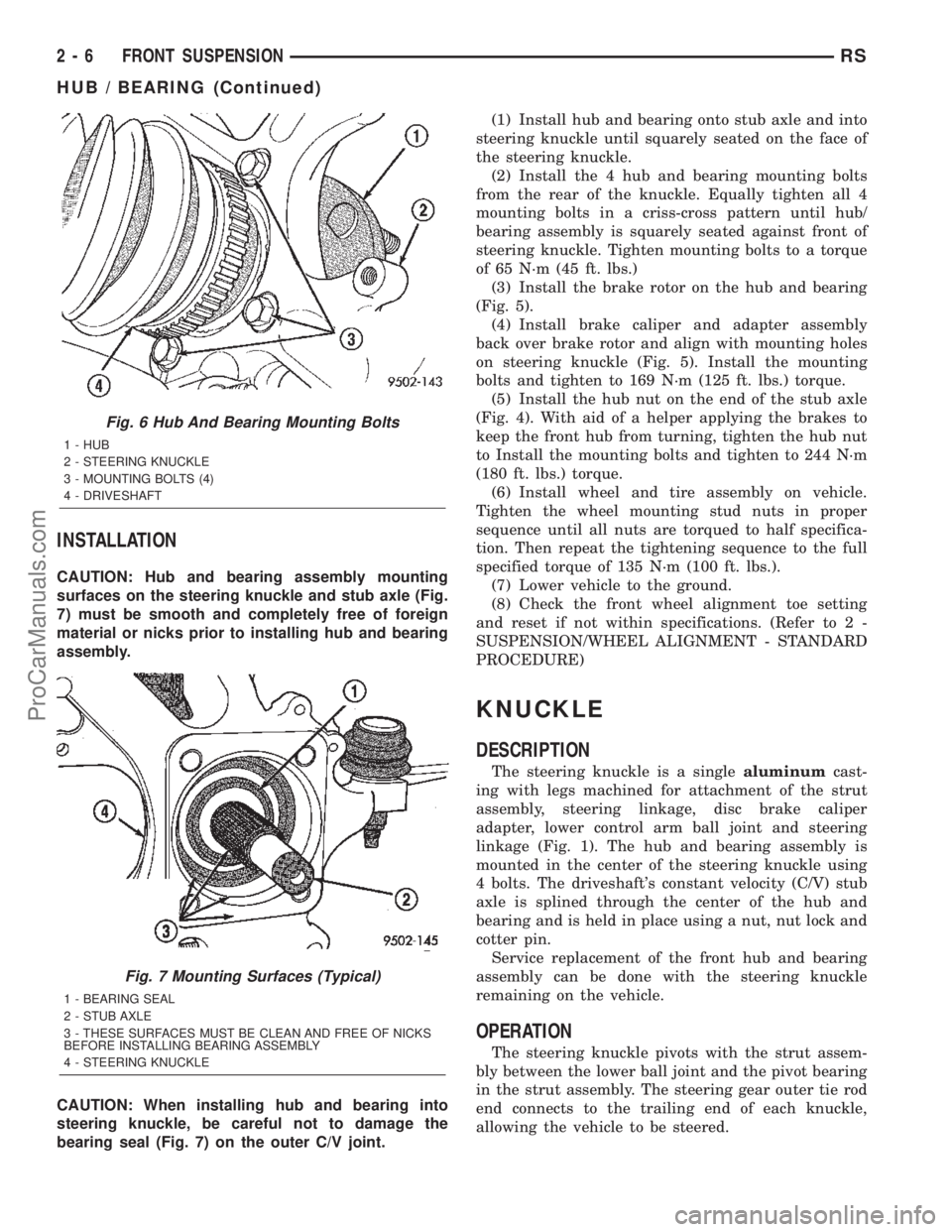
CAUTION: Hub and bearing assembly mounting
surfaces on the steering knuckle and stub axle (Fig.
7) must be smooth and completely free of foreign
material or nicks prior to installing hub and bearing
assembly.
CAUTION: When installing hub and bearing into
steering knuckle, be careful not to damage the
bearing seal (Fig. 7) on the outer C/V joint.(1) Install hub and bearing onto stub axle and into
steering knuckle until squarely seated on the face of
the steering knuckle.
(2) Install the 4 hub and bearing mounting bolts
from the rear of the knuckle. Equally tighten all 4
mounting bolts in a criss-cross pattern until hub/
bearing assembly is squarely seated against front of
steering knuckle. Tighten mounting bolts to a torque
of 65 N´m (45 ft. lbs.)
(3) Install the brake rotor on the hub and bearing
(Fig. 5).
(4) Install brake caliper and adapter assembly
back over brake rotor and align with mounting holes
on steering knuckle (Fig. 5). Install the mounting
bolts and tighten to 169 N´m (125 ft. lbs.) torque.
(5) Install the hub nut on the end of the stub axle
(Fig. 4). With aid of a helper applying the brakes to
keep the front hub from turning, tighten the hub nut
to Install the mounting bolts and tighten to 244 N´m
(180 ft. lbs.) torque.
(6) Install wheel and tire assembly on vehicle.
Tighten the wheel mounting stud nuts in proper
sequence until all nuts are torqued to half specifica-
tion. Then repeat the tightening sequence to the full
specified torque of 135 N´m (100 ft. lbs.).
(7) Lower vehicle to the ground.
(8) Check the front wheel alignment toe setting
and reset if not within specifications. (Refer to 2 -
SUSPENSION/WHEEL ALIGNMENT - STANDARD
PROCEDURE)
KNUCKLE
DESCRIPTION
The steering knuckle is a singlealuminumcast-
ing with legs machined for attachment of the strut
assembly, steering linkage, disc brake caliper
adapter, lower control arm ball joint and steering
linkage (Fig. 1). The hub and bearing assembly is
mounted in the center of the steering knuckle using
4 bolts. The driveshaft's constant velocity (C/V) stub
axle is splined through the center of the hub and
bearing and is held in place using a nut, nut lock and
cotter pin.
Service replacement of the front hub and bearing
assembly can be done with the steering knuckle
remaining on the vehicle.
OPERATION
The steering knuckle pivots with the strut assem-
bly between the lower ball joint and the pivot bearing
in the strut assembly. The steering gear outer tie rod
end connects to the trailing end of each knuckle,
allowing the vehicle to be steered.
Fig. 6 Hub And Bearing Mounting Bolts
1 - HUB
2 - STEERING KNUCKLE
3 - MOUNTING BOLTS (4)
4 - DRIVESHAFT
Fig. 7 Mounting Surfaces (Typical)
1 - BEARING SEAL
2 - STUB AXLE
3 - THESE SURFACES MUST BE CLEAN AND FREE OF NICKS
BEFORE INSTALLING BEARING ASSEMBLY
4 - STEERING KNUCKLE
2 - 6 FRONT SUSPENSIONRS
HUB / BEARING (Continued)
ProCarManuals.com