low beam CHRYSLER CARAVAN 2002 Service Manual
[x] Cancel search | Manufacturer: CHRYSLER, Model Year: 2002, Model line: CARAVAN, Model: CHRYSLER CARAVAN 2002Pages: 2399, PDF Size: 57.96 MB
Page 6 of 2399
FASTENER USAGE
DESCRIPTION
DESCRIPTION - FASTENER USAGE
WARNING: USE OF AN INCORRECT FASTENER
MAY RESULT IN COMPONENT DAMAGE OR PER-
SONAL INJURY.
Fasteners and torque specifications references in
this Service Manual are identified in metric and SAE
format.
During any maintenance or repair procedures, it is
important to salvage all fasteners (nuts, bolts, etc.)
for reassembly. If the fastener is not salvageable, a
fastener of equivalent specification must be used.
DESCRIPTION - THREADED HOLE REPAIR
Most stripped threaded holes can be repaired using
a Helicoilt. Follow the vehicle or Helicoiltrecommen-
dations for application and repair procedures.
INTERNATIONAL SYMBOLS
DESCRIPTION
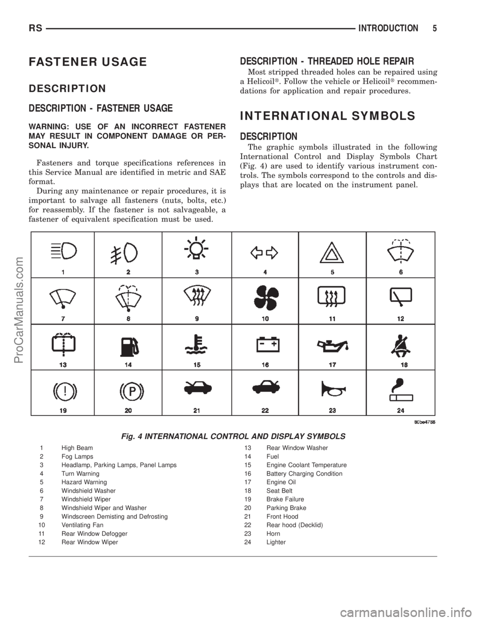
The graphic symbols illustrated in the following
International Control and Display Symbols Chart
(Fig. 4) are used to identify various instrument con-
trols. The symbols correspond to the controls and dis-
plays that are located on the instrument panel.
Fig. 4 INTERNATIONAL CONTROL AND DISPLAY SYMBOLS
1 High Beam 13 Rear Window Washer
2 Fog Lamps 14 Fuel
3 Headlamp, Parking Lamps, Panel Lamps 15 Engine Coolant Temperature
4 Turn Warning 16 Battery Charging Condition
5 Hazard Warning 17 Engine Oil
6 Windshield Washer 18 Seat Belt
7 Windshield Wiper 19 Brake Failure
8 Windshield Wiper and Washer 20 Parking Brake
9 Windscreen Demisting and Defrosting 21 Front Hood
10 Ventilating Fan 22 Rear hood (Decklid)
11 Rear Window Defogger 23 Horn
12 Rear Window Wiper 24 Lighter
RSINTRODUCTION5
ProCarManuals.com
Page 269 of 2399

higher the freeze protection (up to a maximum of
60% by volume glycol).
A refractometer (Special Tool 8286)(Refer to 7 -
COOLING - SPECIAL TOOLS) will test the amount
of glycol in a coolant mixture by measuring the
amount a beam of light bends as it passes through
the fluid.
Some coolant manufactures use other types of gly-
cols into their coolant formulations. Propylene glycol
is the most common new coolant. However, propylene
glycol based coolants do not provide the same freez-
ing protection and corrosion protection and is not rec-
ommended.
CAUTION: Do not mix types of coolantÐcorrosion
protection will be severely reduced.
STANDARD PROCEDURE - COOLANT SERVICE
For engine coolant recommended service schedule,
(Refer to LUBRICATION & MAINTENANCE/MAIN-
TENANCE SCHEDULES - DESCRIPTION).
COOLANT RECOVERY
CONTAINER
DESCRIPTION
The coolant recovery/reserve system cotainer is
mounted in the engine compartment (Fig. 2). The
container is made of plastic.
OPERATION
The coolant recovery system works with the radia-
tor pressure cap to use thermal expansion and con-
traction of the coolant to keep the coolant free of
trapped air. Provides a convenient and safe method
for checking coolant level and adjusting level at
atmospheric pressure without removing the radiator
pressure cap. It also provides some reserve coolant to
cover deaeration, evaporation, or boiling losses.
DIAGNOSIS AND TESTING - COOLANT
RECOVERY SYSTEM
The cooling system is closed and designed to main-
tain coolant level to the top of the radiator.
(1) With the engineoffand cooling systemnot
under pressure, drain several ounces of coolant from
the radiator draincock while observing the coolant
recovery container. Coolant level in the container
should drop.
(2) Remove the radiator pressure cap. The coolant
level should be full to the top radiator neck. If not,and the coolant level in the container is at or above
the MIN mark, there is an air leak in the coolant
recovery system.
(3) Check hose and hose connections to the con-
tainer, radiator filler neck or the pressure cap seal to
the radiator filler neck for leaks.
REMOVAL
(1) Raise the vehicle on hoist.
(2) Remove the lower attaching screws (Fig. 2).
(3) Lower the vehicle.
(4) Remove the upper attaching screw (Fig. 2).
(5) Disconnect recovery hose from container (Fig.
2).
(6) Remove the recovery container.
INSTALLATION
(1) Connect the recovery hose to container (Fig. 2).
(2) Position the recovery container on the frame
rail (Fig. 2).
(3) Install the upper attaching screw and tighten
to 7 N´m (60 in. lbs.) (Fig. 2).
(4) Raise the vehicle on hoist.
(5) Install the lower attaching screws and tighten
to 8.5 N´m (75 in. lbs.) (Fig. 2).
(6) Lower the vehicle.
(7) Add coolant to container as necessary. (Refer to
7 - COOLING - STANDARD PROCEDURE)
Fig. 2 Coolant Recovery Container
1 - UPPER BOLT ATTACHING TO BATTERY TRAY
2 - COOLANT RECOVERY CONTAINER
3 - UPPER BOLT
4 - HOSE
5 - LOWER BOLT (QTY. 2)
6 - LEFT SIDE FRAME RAIL
7 - 20 ENGINERS
COOLANT (Continued)
ProCarManuals.com
Page 280 of 2399
(4) Install the radiator upper support crossmem-
ber. (Refer to 23 - BODY/EXTERIOR/GRILLE OPEN-
ING REINFORCEMENT - INSTALLATION)
(5) Install the upper radiator mounts to the cross-
member bolts, if removed. Tighten to 8 N´m (70 in.
lbs.).
(6) Install the radiator upper hose to the support
clip (2.4L engine).
RADIATOR FAN RELAY
DESCRIPTION
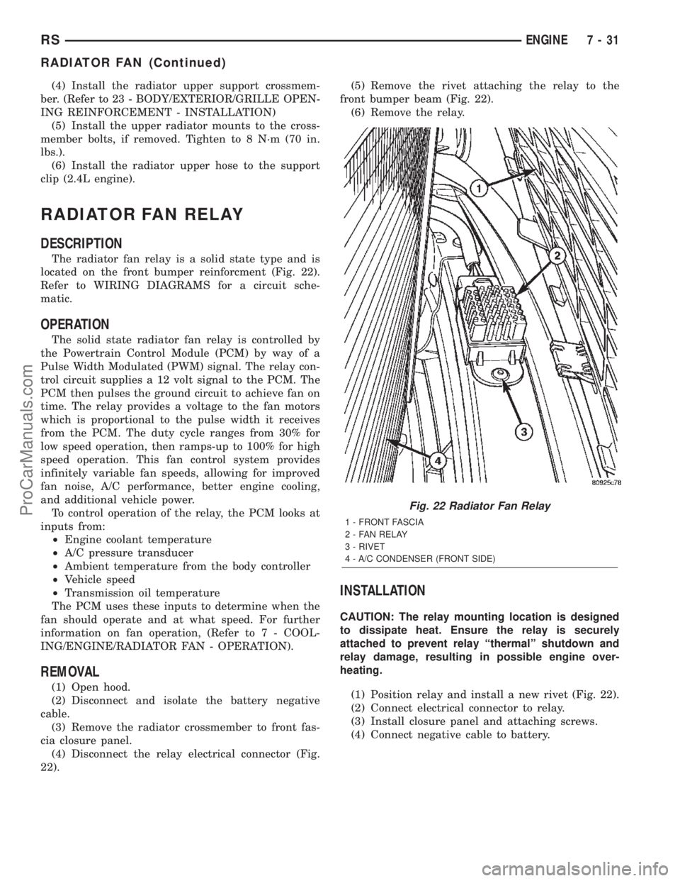
The radiator fan relay is a solid state type and is
located on the front bumper reinforcment (Fig. 22).
Refer to WIRING DIAGRAMS for a circuit sche-
matic.
OPERATION
The solid state radiator fan relay is controlled by
the Powertrain Control Module (PCM) by way of a
Pulse Width Modulated (PWM) signal. The relay con-
trol circuit supplies a 12 volt signal to the PCM. The
PCM then pulses the ground circuit to achieve fan on
time. The relay provides a voltage to the fan motors
which is proportional to the pulse width it receives
from the PCM. The duty cycle ranges from 30% for
low speed operation, then ramps-up to 100% for high
speed operation. This fan control system provides
infinitely variable fan speeds, allowing for improved
fan noise, A/C performance, better engine cooling,
and additional vehicle power.
To control operation of the relay, the PCM looks at
inputs from:
²Engine coolant temperature
²A/C pressure transducer
²Ambient temperature from the body controller
²Vehicle speed
²Transmission oil temperature
The PCM uses these inputs to determine when the
fan should operate and at what speed. For further
information on fan operation, (Refer to 7 - COOL-
ING/ENGINE/RADIATOR FAN - OPERATION).
REMOVAL
(1) Open hood.
(2) Disconnect and isolate the battery negative
cable.
(3) Remove the radiator crossmember to front fas-
cia closure panel.
(4) Disconnect the relay electrical connector (Fig.
22).(5) Remove the rivet attaching the relay to the
front bumper beam (Fig. 22).
(6) Remove the relay.
INSTALLATION
CAUTION: The relay mounting location is designed
to dissipate heat. Ensure the relay is securely
attached to prevent relay ªthermalº shutdown and
relay damage, resulting in possible engine over-
heating.
(1) Position relay and install a new rivet (Fig. 22).
(2) Connect electrical connector to relay.
(3) Install closure panel and attaching screws.
(4) Connect negative cable to battery.
Fig. 22 Radiator Fan Relay
1 - FRONT FASCIA
2 - FAN RELAY
3 - RIVET
4 - A/C CONDENSER (FRONT SIDE)
RSENGINE7-31
RADIATOR FAN (Continued)
ProCarManuals.com
Page 304 of 2399

COOLANT
DESCRIPTION
Coolant flows through the engine water jackets
and cylinder heads absorbing heat produced by the
engine during operation. The coolant carries heat to
the radiator and heater core. Here it is transferred to
ambient air passing through the radiator and heater
core fins.
The required ethylene-glycol (antifreeze) and water
mixture depends upon the climate and vehicle oper-
ating conditions. The recommended mixture of 50/50
ethylene-glycol and water will provide protection
against freezing to -37 deg. C (-35 deg. F). The anti-
freeze concentrationmust alwaysbe a minimum of
44 percent, year-round in all climates.If percentage
is lower than 44 percent, engine parts may be
eroded by cavitation, and cooling system com-
ponents may be severely damaged by corrosion.
Maximum protection against freezing is provided
with a 68 percent antifreeze concentration, which
prevents freezing down to -67.7 deg. C (-90 deg. F). A
higher percentage will freeze at a warmer tempera-
ture. Also, a higher percentage of antifreeze can
cause the engine to overheat because the specific
heat of antifreeze is lower than that of water.
100 Percent Ethylene-GlycolÐShould Not Be Used in
Chrysler Vehicles
Use of 100 percent ethylene-glycol will cause for-
mation of additive deposits in the system, as the cor-
rosion inhibitive additives in ethylene-glycol require
the presence of water to dissolve. The deposits act as
insulation, causing temperatures to rise to as high as
149 deg. C (300 deg. F). This temperature is hot
enough to melt plastic and soften solder. The
increased temperature can result in engine detona-
tion. In addition, 100 percent ethylene-glycol freezes
at -22 deg. C (-8 deg. F ).
Propylene-glycol FormulationsÐShould Not Be Used in
Chrysler Vehicles
Propylene-glycol formulations do not meet
Chrysler coolant specifications.It's overall effec-
tive temperature range is smaller than that of ethyl-
ene-glycol. The freeze point of 50/50 propylene-glycol
and water is -32 deg. C (-26 deg. F). 5 deg. C higher
than ethylene-glycol's freeze point. The boiling point
(protection against summer boil-over) of propylene-
glycol is 125 deg. C (257 deg.F)at96.5 kPa (14 psi),
compared to 128 deg. C (263 deg. F) for ethylene-gly-
col. Use of propylene-glycol can result in boil-over or
freeze-up in Chrysler vehicles, which are designed for
ethylene-glycol. Propylene glycol also has poorer heat
transfer characteristics than ethylene glycol. Thiscan increase cylinder head temperatures under cer-
tain conditions.
Propylene-glycol/Ethylene-glycol MixturesÐShould Not Be
Used in Chrysler Vehicles
Propylene-glycol/ethylene-glycol Mixtures can
cause the destabilization of various corrosion inhibi-
tors, causing damage to the various cooling system
components. Also, once ethylene-glycol and propy-
lene-glycol based coolants are mixed in the vehicle,
conventional methods of determining freeze point will
not be accurate. Both the refractive index and spe-
cific gravity differ between ethylene glycol and propy-
lene glycol.
CAUTION: Richer antifreeze mixtures cannot be
measured with normal field equipment and can
cause problems associated with 100 percent ethyl-
ene-glycol.
DIAGNOSIS AND TESTING - COOLANT
CONCENTRATION TESTING
Coolant concentration should be checked when any
additional coolant was added to system or after a
coolant drain, flush and refill. The coolant mixture
offers optimum engine cooling and protection against
corrosion when mixed to a freeze point of -37ÉC
(-34ÉF) to -59ÉC (-50ÉF). The use of a hydrometer or a
refractometer can be used to test coolant concentra-
tion.
A hydrometer will test the amount of glycol in a
mixture by measuring the specific gravity of the mix-
ture. The higher the concentration of ethylene glycol,
the larger the number of balls that will float, and
higher the freeze protection (up to a maximum of
60% by volume glycol).
A refractometer will test the amount of glycol in a
coolant mixture by measuring the amount a beam of
light bends as it passes through the fluid.
Some coolant manufactures use other types of gly-
cols into their coolant formulations. Propylene glycol
is the most common new coolant. However, propylene
glycol based coolants do not provide the same freez-
ing protection and corrosion protection and is not rec-
ommended.
CAUTION: Do not mix types of coolantÐcorrosion
protection will be severely reduced.
RGENGINE7a-15
ProCarManuals.com
Page 488 of 2399
INSTRUMENT CLUSTER
TABLE OF CONTENTS
page page
INSTRUMENT CLUSTER
DESCRIPTION..........................1
OPERATION............................1
DIAGNOSIS AND TESTING
DIAGNOSIS AND TESTING - SELF-
DIAGNOSTICS.........................2
DIAGNOSIS AND TESTING - CLUSTER
DIAGNOSIS...........................2
REMOVAL.............................11
INSTALLATION.........................12CLUSTER LENS
REMOVAL.............................12
INSTALLATION.........................12
MECHANICAL TRANSMISSION RANGE
INDICATOR
REMOVAL.............................12
INSTALLATION.........................12
RED BRAKE WARNING INDICATOR
DESCRIPTION.........................13
OPERATION...........................13
INSTRUMENT CLUSTER
DESCRIPTION
The instrumentation gauges are contained in a
subdial assembly within the instrument cluster. The
individual gauges are not serviceable. If one of the
cluster gauges becomes faulty, the entire cluster
would require replacement.
The mechanical instrument cluster with a tachom-
eter is equipped with a electronic vacuum fluorescent
transmission range indicator (PRND3L), odometer,
and trip odometer display.
The mechanical instrument cluster without a
tachometer is equipped with a cable operated trans-
mission range indicator (PRND21) and a vacuum flu-
orescent odometer display. It also has the following
indicators:
²Turn Signals
²High Beam
²Oil Pressure
²MIL
The instrument cluster is equipped with the follow-
ing warning lamps.
²Lift Gate Ajar
²Low Fuel Level
²Low Windshield Washer Fluid Level
²Cruise
²Battery Voltage
²Fasten Seat Belt
²Door Ajar
²Coolant Temperature
²Anti-Lock Brake
²Brake
²Airbag
²Traction Control
²AutostickThe mechanical instrument cluster without a
tachometer also has the following warning lamps:
²Turns Signals
²High Beam
²Oil Pressure
²Malfunction Indicator Lamp (MIL)
WATER IN FUEL LAMP - EXPORT
The Water In Fuel Lamp is located in the instru-
ment cluster. When moisture is found within the fuel
system, the sensor sends a message via the PCI data
bus to the instrument cluster. The sensor is located
underneath the vehicle, directly above the rear axle.
The sensor is housed within the fuel filter/water sep-
arator assembly cover. The sensor is not serviced sep-
arately. If found defective, the entire assembly cover
must be replaced.
OPERATION
Refer to the vehicle Owner's Manual for operation
instructions and conditions for the Instrument Clus-
ter Gauges.
WATER IN FUEL LAMP - EXPORT
The Water In Fuel Sensor is a resistive type
switch. It is calibrated to sense the different resis-
tance between diesel fuel and water. When water
enters the fuel system, it is caught in the bottom of
the fuel filter/water separator assembly, where the
sensor is located. Water has less resistance than die-
sel fuel. The sensor then sends a PCI data bus mes-
sage to the instrument cluster to illuminate the
lamp.
If the lamp is inoperative, perform the self diag-
nostic test on the instrument cluster to check the
lamp operation before continuing diagnosis.
RSINSTRUMENT CLUSTER8J-1
ProCarManuals.com
Page 503 of 2399
OPERATION - TURN SIGNAL SYSTEM.......21
DIAGNOSIS AND TESTING - MULTI-
FUNCTION SWITCH...................22
REMOVAL.............................22
INSTALLATION.........................22
PARK/TURN SIGNAL LAMP
REMOVAL.............................22
INSTALLATION.........................22
PARK/TURN SIGNAL LAMP - EXPORT
REMOVAL.............................22
INSTALLATION.........................23
REAR FOG LAMP - EXPORT
DESCRIPTION.........................23REPEATER LAMP - EXPORT
REMOVAL.............................23
INSTALLATION.........................23
TAIL LAMP
REMOVAL.............................23
INSTALLATION.........................23
TAIL LAMP - EXPORT
REMOVAL.............................23
INSTALLATION.........................24
TAIL LAMP UNIT
REMOVAL.............................24
INSTALLATION.........................24
LAMPS/LIGHTING - EXTERIOR
DESCRIPTION
LAMP SYSTEMS
Lighting circuits are protected by fuses. Lighting
circuits require an overload protected power source,
on/off device, lamps and body ground to operate prop-
erly. Plastic lamps require a wire in the harness to
supply body ground to the lamp socket. Replace sock-
ets and bulbs that are corroded.
Some of the interior and exterior lighting functions
are governed by the Body Control Module (BCM).
The headlamp, dome, and the door ajar switches pro-
vide signals to the BCM. The BCM in turn sends a
Programmable Communication Interface (PCI) bus
message to the Front Control Module (FCM) to
enable the necessary drivers to set the required illu-
mination configuration.
Wire connectors can make intermittent contact or
become corroded. Before coupling wire connectors,
inspect the terminals inside the connector. Male ter-
minals should not be bent or disengaged from the
insulator. Female terminals should not be sprung
open or disengaged from the insulator. Bent and
sprung terminals can be repaired using needle nose
pliers and pick tool. Corroded terminals appear
chalky or green. Corroded terminals should be
replaced to avoid recurrence of the problem symp-
toms.
Begin electrical system failure diagnosis by testing
related fuses in the fuse block and intelligent power
module. Verify that bulbs are in good condition and
test continuity of the circuit ground. Refer to the
appropriate wiring information.
AUTOMATIC HEADLAMP SYSTEM
The Automatic Headlamp system turns the instru-
mentation and exterior illumination lamps ON when
the ambient light levels are Night and the engine
RPM is 450 or above, and OFF when light levels are
Day.
DAYTIME RUNNING LAMPS
Operating the high-beam headlamps at reduced
power provides daytime running lamps, which are
required on all new Canadian vehicles.
HEADLAMPS ON WITH WINDSHIELD WIPERS
For vehicles equipped with the Automatic Head-
lamp System, the instrumentation and exterior illu-
mination lamps will be turned ON when the
headlamp switch is in the AUTO position, RPM >
450 and the windshield wipers have been in the
intermittent, low or high mode of operation for more
than ten seconds. When the windshield wipers are
turned OFF the Body Control Module will determine
if the instrumentation and exterior illumination
lamps should remain ON base upon the current
ambient light level.
HEADLAMP SYSTEM
The configuration of the headlamp system of head-
lamps, park lamps and fog lamps is determined by
the BCM. The BCM determines the lighting configu-
ration as a result of the inputs from the ignition
switch, headlamp switch and multi-function switch. A
PCI bus is transmitted from the BCM to the FCM to
enable the necessary drivers to set the illumination
configuration. Four wires are connected between the
headlamp switch and the BCM. The first wire con-
tains information regarding the position of the head-
lamp switch (Off, Automatic Headlamps, Automatic
Headlamp switch fog, Park with Fog, Head, or Head
with Fog Lamps). The second wire contains informa-
tion regarding the position of the dimmer switch
(Dome Lamp, Daytime Brightness, Dimming Level or
Off). The third wire is a dedicated signal return
(ground) wire. The fourth wire provides power to the
front fog lamp indicator.
HEADLAMP TIME DELAY SYSTEM
The headlamp time delay system is controlled by
the Body Control Module (BCM) via a PCI bus mes-
8L - 2 LAMPS/LIGHTING - EXTERIORRS
ProCarManuals.com
Page 504 of 2399

sage transmitted by the BCM to the FCM to turn off
the headlamps.
OPERATION
AUTOMATIC HEADLAMP SYSTEM
Automatic headlamps are controlled by the Body Con-
trol Module (BCM). With the headlamp switch in the
AUTO position, the BCM will control the headlamp, park-
ing, side marker, tail and instrumentation lamps based on
ambient light levels. Ambient light levels are monitored
by the BCM using the Day/Night signal and Electrochro-
matic Mirror (ECM) present from the Compass Mini Trip
(CMTC) located on the front windshield in front of the
rear view mirror ECM. Ambient light readings are aver-
aged to limit cycling the lamps ON and OFF when pass-
ing through areas with varying light levels. The
automatic headlamps will only function when the engine
is running with RPM > 450. When the headlamp switch is
in the AUTO position (Automatic mode), the Headlamp
Time Delay system will function when the ignition switch
is placed in any position other than run/start.
DAYTIME RUNNING LAMPS
Power is reduced using pulse-width modulation to
the high beams, where by the power is switched on
and off rapidly instead of remaining on continuously.
The duration and interval of the power pulses is pro-
grammed into the FCM.
HEADLAMP SYSTEM
The headlamp system will default to headlamps
ON position when ignition switch is ON and when an
open or short circuit failure occurs on the headlamp
switch input. The system will return to normal oper-
ation when the open or short is repaired. A fault will
be reported by the BCM when a failure occurs on the
dimmer or headlamp switch input.
If the exterior lamps are ON and the headlamp
switch is in any position other than OFF or AUTO
and with the ignition switch OFF (LOCK) after 3
minutes the BCM sends a message via PCI bus to
the FCM informing the FCM to turn off the head-
lamps, park lamps and fog lamps. This feature pre-
vents the vehicle battery from being discharged when
the vehicle lights have been left ON.
HEADLAMP TIME DELAY SYSTEM
The headlamp time delay system is activated by
turning the headlamps ON (high or low beam) while
the engine is running, turning the ignition switch
OFF, and then turning the headlamp switch OFF
within 45 seconds. The system will not activate if
more than 45 seconds elapse between ignition switch
OFF and headlamp switch OFF. The BCM will allow
the headlamps to remain ON for 90 seconds (config-urable) before they automatically turn off (If the key
is in the ignition during the headlamp time delay
mode, then both the headlamps and park lamps
(including panel dimming) will be ON). Refer to the
Owner's Manual for more information.
If the headlamp switch is in the Auto Headlamp
Position, the headlamps are ON due to the night sig-
nal from the CMTC and the ignition switch is in any
position other than run/start, the BCM shall enter a
90 second (configurable) Auto Headlamps time delay
mode. If the key is in the ignition during the head-
lamp time delay mode, then both the headlamps and
park lamps (including panel dimming) will be ON. If
the key is not in the ignition, then only the head-
lamps will be ON. The BCM will allow the head-
lamps to remain ON for 90 seconds before they
automatically turn OFF. Refer to the Owner's Man-
ual for more information.
OPTICAL HORN/HIGH BEAMS
When the multi-function switch is pulled to the
first detent (optical horn) signal, the headlamps are
ON, key-in the ignition the BCM shall send a mes-
sage via PCI bus to the FCM to turn on the head-
lamps drivers to illuminate all four filaments (Low
and High beams). When the multi-function switch is
pulled to the second detent (high beam) signal and
the headlamps are ON, the BCM shall send a mes-
sage via PCI bus to the FCM to turn on the head-
lamps drivers. The High Beams are illuminated and
the Low Beams and Fog Lamps (if ON) are extin-
guished. If the headlamps were in the high beam
configuration when power was removed from the
headlamps, the headlamps will be configured as low
beam the next time they are activated.
WARNING
WARNING: EYE PROTECTION SHOULD BE USED
WHEN SERVICING GLASS COMPONENTS. PER-
SONAL INJURY CAN RESULT.
CAUTION: Do not touch the glass of halogen bulbs
with fingers or other possibly oily surface, reduced
bulb life will result. Do not use bulbs other than
those indicated in the Bulb Application table. Dam-
age to lamp and/or Daytime Running Lamp Module
can result. Do not use fuses, circuit breakers or
relays having greater amperage value than indi-
cated on the fuse panel or in the Owners Manual.
CAUTION: Do not use bulbs other than those listed
in the Bulb Application Table. Damage to lamp can
result. Do not touch halogen bulbs with fingers or
other oily surfaces. Bulb life will be reduced.
RSLAMPS/LIGHTING - EXTERIOR8L-3
LAMPS/LIGHTING - EXTERIOR (Continued)
ProCarManuals.com
Page 508 of 2399
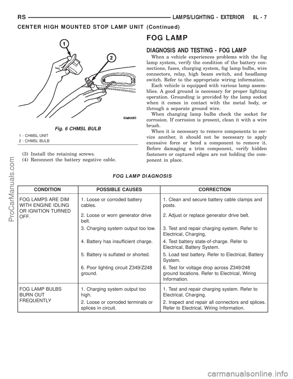
(3) Install the retaining screws.
(4) Reconnect the battery negative cable.
FOG LAMP
DIAGNOSIS AND TESTING - FOG LAMP
When a vehicle experiences problems with the fog
lamp system, verify the condition of the battery con-
nections, fuses, charging system, fog lamp bulbs, wire
connectors, relay, high beam switch, and headlamp
switch. Refer to the appropriate wiring information.
Each vehicle is equipped with various lamp assem-
blies. A good ground is necessary for proper lighting
operation. Grounding is provided by the lamp socket
when it comes in contact with the metal body, or
through a separate ground wire.
When changing lamp bulbs check the socket for
corrosion. If corrosion is present, clean it with a wire
brush.
When it is necessary to remove components to ser-
vice another, it should not be necessary to apply
excessive force or bend a component to remove it.
Before damaging a trim component, verify hidden
fasteners or captured edges are not holding the com-
ponent in place.
FOG LAMP DIAGNOSIS
CONDITION POSSIBLE CAUSES CORRECTION
FOG LAMPS ARE DIM
WITH ENGINE IDLING
OR IGNITION TURNED
OFF.1. Loose or corroded battery
cables.1. Clean and secure battery cable clamps and
posts.
2. Loose or worn generator drive
belt.2. Adjust or replace generator drive belt.
3. Charging system output too low. 3. Test and repair charging system. Refer to
Electrical, Charging,
4. Battery has insufficient charge. 4. Test battery state-of-charge. Refer to
Electrical, Battery System.
5. Battery is sulfated or shorted. 5. Load test battery. Refer to Electrical, Battery
System.
6. Poor lighting circuit Z349/Z248
ground.6. Test for voltage drop across Z349/248
ground locations. Refer to Electrical, Wiring
Information.
FOG LAMP BULBS
BURN OUT
FREQUENTLY1. Charging system output too
high.1. Test and repair charging system. Refer to
Electrical, Charging.
2. Loose or corroded terminals or
splices in circuit.2. Inspect and repair all connectors and splices.
Refer to Electrical, Wiring Information.
Fig. 6 CHMSL BULB
1 - CHMSL UNIT
2 - CHMSL BULB
RSLAMPS/LIGHTING - EXTERIOR8L-7
CENTER HIGH MOUNTED STOP LAMP UNIT (Continued)
ProCarManuals.com
Page 513 of 2399

(4) Install the headlamp unit.
(5) Connect the battery negative cable.
HEADLAMP
DIAGNOSIS AND TESTING - HEADLAMP
When a vehicle experiences problems with the
headlamp system, verify the condition of the battery
connections, fuses, charging system, headlamp bulbs,
wire connectors, relay, high beam switch, dimmer
switch, and headlamp switch. Refer to the appropri-
ate wiring information.
Each vehicle is equipped with various lamp assem-
blies. A good ground is necessary for proper lighting
operation. Grounding is provided by the lamp socket
when it comes in contact with the metal body, or
through a separate ground wire.
When changing lamp bulbs check the socket for
corrosion. If corrosion is present, clean it with a wire
brush.
When it is necessary to remove components to ser-
vice another, it should not be necessary to apply
excessive force or bend a component to remove it.
Before damaging a trim component, verify hidden
fasteners or captured edges are not holding the com-
ponent in place.
HEADLAMP DIAGNOSIS
CONDITION POSSIBLE CAUSES CORRECTION
HEADLAMPS ARE DIM
WITH ENGINE IDLING
OR IGNITION TURNED
OFF.1. Loose or corroded battery
cables.1. Clean and secure battery cable clamps and
posts.
2. Loose or worn generator drive
belt.2. Adjust or replace generator drive belt.
3. Charging system output too low. 3. Test and repair charging system, refer to
Electrical, Charging
4. Battery has insufficient charge. 4. Test battery state-of-charge, refer to
Electrical, Battery System.
5. Battery is sulfated or shorted. 5. Load test battery, refer to Electrical, Battery
System.
6. Poor lighting circuit Z343/Z344-
ground.6. Test for voltage drop across Z343/Z344-
ground locations, refer to Electrical, Wiring
Diagram Information.
HEADLAMP BULBS
BURN OUT
FREQUENTLY.1. Integrated Power Module (IPM)
not controlling voltage.1. Test and repair Integrated Power Module.
2. Loose or corroded terminals or
splices in circuit.2. Inspect and repair all connectors and splices.
Refer to Electrical, Wiring Information.
Fig. 11 FRONT POSITION LAMP
1 - TURN SIGNAL LAMP
2 - HIGH BEAM LAMP
3 - FRONT POSITION LAMP
4 - LOW BEAM LAMP
8L - 12 LAMPS/LIGHTING - EXTERIORRS
FRONT POSITION LAMP - EXPORT (Continued)
ProCarManuals.com
Page 515 of 2399

REMOVAL
(1) Disconnect and isolate the battery negative
cable.
(2) Remove headlamp unit retaining screws.
(3) Remove headlamp unit to expose back of unit.
(4) Remove wiring connector from bulb.
(5) Rotate headlamp bulb retaining ring counter-
clockwise.
(6) Pull headlamp bulb and remove from headlamp
unit (Fig. 12).
INSTALLATION
(1) Install headlamp bulb to the headlamp unit.
(2) Install headlamp bulb retaining ring.
(3) Connect wiring connector to bulb.
(4) Install the headlamp unit.
(5) Install headlamp unit retaining screws.
(6) Reconnect the battery negative cable.
HEADLAMP - EXPORT
REMOVAL
(1) Disconnect and isolate the battery negative
cable.
(2) Remove the headlamp unit.
(3) Remove the cover (high beam lamp) or rubber
boot (low beam lamp) to access bulbs (Fig. 13).
(4) Disconnect the wire harness connector.
(5) Disengage spring clip from headlamp.
(6) Pull headlamp bulb from back of headlamp
unit.
INSTALLATION
(1) Insert headlamp bulb into headlamp unit.
(2) Engage spring clip to headlamp.
(3) Connect wire harness connector.
(4) Install the cover (high beam lamp) or rubber
boot (low beam lamp) to headlamp unit.
(5) Install the headlamp unit.
(6) Connect the battery negative cable.
Fig. 12 HEADLAMP
1 - HEADLAMP
2 - HEADLAMP UNIT
Fig. 13 HEADLAMP UNIT
1 - HIGH BEAM LAMP
2 - HEADLAMP LEVELING MOTOR
3 - LOW BEAM LAMP
4 - TURN LAMP
8L - 14 LAMPS/LIGHTING - EXTERIORRS
HEADLAMP (Continued)
ProCarManuals.com