seat adjustment CHRYSLER CARAVAN 2002 User Guide
[x] Cancel search | Manufacturer: CHRYSLER, Model Year: 2002, Model line: CARAVAN, Model: CHRYSLER CARAVAN 2002Pages: 2399, PDF Size: 57.96 MB
Page 602 of 2399
cle. Check for battery voltage at the fused B(+)
circuit cavity of the power seat wire harness connec-
tor for the power seat switch. If OK, go to Step 4. If
not OK, repair the open fused B(+) circuit to the
power seat circuit breaker under the seat as
required.
(4) Check for continuity between the ground cir-
cuit cavity of the power seat wire harness connector
for the power seat switch and a good ground. There
should be continuity. If OK, go to Step 5. If not OK,
repair the open ground circuit to ground as required.
(5) Test the power seat switch. Refer toDiagnosis
and Testing Power Seat Switchin this section. If
the switch tests OK, test the circuits of the power
seat wire harness between the inoperative power seat
track adjuster motor and the power seat switch for
shorts or opens. If the circuits check OK, replace the
faulty power seat track unit. If the circuits are not
OK, repair the power seat wire harness as required.
REMOVAL
WARNING: SOME VEHICLES ARE EQUIPPED WITH
SEATBACK MOUNTED AIRBAGS. BEFORE
ATTEMPTING TO DIAGNOSE OR SERVICE ANY
SEAT OR POWER SEAT SYSTEM COMPONENT
YOU MUST FIRST DISCONNECT AND ISOLATE THE
BATTERY NEGATIVE CABLE. THEN WAIT TWO MIN-
UTES FOR THE SYSTEM CAPACITOR TO DIS-
CHARGE BEFORE FURTHER SYSTEM SERVICE.
THIS IS THE ONLY SURE WAY TO DISABLE THE
AIRBAG SYSTEM. FAILURE TO DO SO COULD
RESULT IN ACCIDENTAL AIRBAG DEPLOYMENT
AND POSSIBLE PERSONAL INJURY.
(1) Remove the appropriate seat from the vehicle
and place it on a clean work surface(Refer to 23 -
BODY/SEATS/SEAT - REMOVAL).
(2) Remove the Body Control Module retaining
screws.
(3) Disconnect the body control module electrical
connectors and remove the body control module from
the power seat track.
(4) Remove the rear fabric blocker trim panel from
the rear of the front seat.
(5) Remove the seat side cover and power seat
switch as an assembly (Refer to 23 - BODY/SEATS/
SEAT CUSHION SIDE COVERS - REMOVAL).
(6) Disconnect all electrical connectors connecting
the power seat track to the seat assembly.
(7) Pull the seat back trim cover up slightly to
access and remove the two seat back frame mounting
bolts and also remove two seat back recliner bolts.
(8) Remove four seat track mounting bolts from
the seat cushion pan.
(9) Remove the power seat track from the seat.
INSTALLATION
(1) Position the seat cushion on the seat track.
(2) Install the four seat track retaining bolts in the
seat cushion pan. Torque the bolts to 28.5 N´m.
(3) Position the seat back and install the two seat
back frame mounting bolts and the two seat back
recliner bolts. Torque the bolts to 55 N´m.
(4) Route and connect the electrical connectors
between the power seat track and the seat assembly.
(5) Install the seat side cover and power seat
switch as an assembly (Refer to 23 - BODY/SEATS/
SEAT CUSHION SIDE COVERS - INSTALLATION).
(6) Install the rear fabric blocker trim panel on the
rear of the front seat.
(7) Position the body control module and connect
the body control module electrical connectors.
(8) Install the Body Control Module retaining
screws.
(9) Install the seat assembly in the vehicle (Refer
to 23 - BODY/SEATS/SEAT - INSTALLATION).
PASSENGER POWER SEAT
TRACK
DESCRIPTION
The eight-way power seat option includes a electri-
cally operated power seat track unit located under
each front seat. The power seat circuit breaker is
mounted on the rear of the power seat track, just
behind the seat rear trim panel. The lower half of the
power seat track is secured to the floor panel via four
studs and nuts that must be accessed from the
underside of the vehicle. Four bolts secure the bot-
tom of the seat cushion frame to the upper half of the
power seat track unit. Four additional bolts secure
the seat back frame to the power seat track unit.
The power seat track unit includes four reversible
electric motors that are secured to the upper half of
the track unit. Each motor moves the seat adjuster
through a combination of worm-drive gearboxes and
screw-type drive units.
The front and rear of the seat are operated by two
separate vertical adjustment motors. These motors
can be operated independently of each other, tilting
the entire seat assembly forward or rearward; or,
they can be operated in unison by selecting the
proper power seat switch functions, which will raise
or lower the entire seat assembly. A third motor is
the horizontal adjustment motor, which moves the
seat track in the forward and rearward directions.
The forth motor is the recliner adjustment motor,
which moves the seat back in the forward and rear-
ward directions.
RSPOWER SEAT SYSTEM8N-61
DRIVER POWER SEAT TRACK (Continued)
ProCarManuals.com
Page 644 of 2399

CONDITION POSSIBLE CAUSES CORRECTION
COWL GRILLE NOZZLE
WILL NOT FLOW.1. FROZEN NOZZLE. 1. MOVE VEHICLE INTO HEATED AREA TO
ALLOW TIME TO THAW NOZZLE. ASSURE
WASHER FLUID IS PROPERLY BLENDED
FOR AMBIENT OUTSIDE TEMPERATURES.
2. NOZZLE HOSE NOT
FLOWING.2. ASSURE NOZZLE HOSE IS NOT
PINCHED, LOOSE, BROKEN, OR
DISCONNECTED. IF NOT OK, PROPERLY
ROUTE OR REPAIR NOZZLE HOSE.
3. NOZZLE HOSE PLUGGED
BY CONTAMINATION.3. CLEAN NOZZLE HOSE OF
CONTAMINATION. DETERMINE SOURCE
OF CONTAMINATION. INSPECT
RESERVOIR FOR EXCESSIVE
CONTAMINATION. CLEAN SYSTEM AS
REQUIRED.
4. NOZZLE PLUGGED BY
CONTAMINATION.4. CLEAN NOZZLE OF CONTAMINATION
OR REPLACE NOZZLE. DETERMINE
SOURCE OF CONTAMINATION. INSPECT
RESERVOIR FOR EXCESSIVE
CONTAMINATION. CLEAN SYSTEM AS
REQUIRED.
5. DEFECTIVE WASHER HOSE
CHECK VALVE.5. REPLACE COWL GRILLE PANEL
WASHER HOSE/CHECK VALVE ASSEMBLY.
WASHER FLUID OUTPUT IS
LOW.1. PARTIALLY PINCHED HOSE. 1. ASSURE WASHER HOSE IS NOT
PARTIALLY PINCHED. IF NOT OK,
PROPERLY ROUTE HOSE.
2. REVERSE POLARITY TO
PUMP.2. CHECK FOR CROSSED CIRCUIT TO
PUMP. IF NOT OK, REPAIR CIRCUIT.
3. WORN OUT WASHER PUMP. 3. REPLACE WASHER PUMP.
COWL GRILLE NOZZLE
STREAM OVERSHOOTS
WINDSHIELD.1. NOZZLE NOT SEATED IN
COWL GRILLE.1. ASSURE NOZZLE IS SNAPPED IN
PLACE.
2. NOZZLE JET(S) OUT OF
ADJUSTMENT.2. ADJUST NOZZLE JET(S) USING A
SAFETY PIN.
WIPER WILL NOT CYCLE
WHEN WASHER SELECT
SWITCH IS DEPRESSED.1. DEFECTIVE IPM. 1. REFER TO IPM DIAGNOSTIC
PROCEDURES IN WIRING DIAGRAMS.
2. DEFECTIVE IPM/BODY
CONTROLLER.2. REFER TO IPM/BODY CONTROLLER
DIAGNOSTIC PROCEDURES IN WIRING
DIAGRAMS.
WASHER OPERATES
INTERMITTENTLY.1. INTERMITTENT MOTOR
GROUND.INTERMITTENT GROUND BETWEEN
MOTOR CONNECTOR TERMINAL 1 AND
IPM PIN 20.
2. INTERMITTENT OPEN IN
WASHER SELECT SWITCH.2. (Refer to 8 - ELECTRICAL/LAMPS/
LIGHTING - EXTERIOR/MULTI-FUNCTION
SWITCH - DIAGNOSIS AND TESTING).
3. DEFECTIVE WASHER
MOTOR.3. REPLACE WASHER MOTOR.
RSWIPERS/WASHERS8R-7
WIPERS/WASHERS (Continued)
ProCarManuals.com
Page 1654 of 2399
(11) Install adapter plate axle seal using Tool
L-4520 (inverted), and driver handle C-4171.
(12) Check differential turning torque. (Refer to 21
- TRANSMISSION/TRANSAXLE/AUTOMATIC -
31TH/BEARINGS - ADJUSTMENTS)
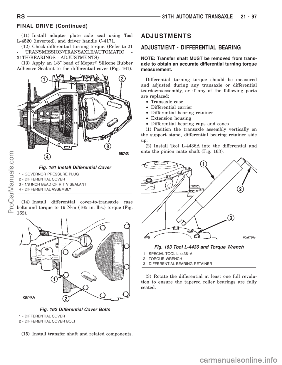
(13) Apply an 1/8º bead of MopartSilicone Rubber
Adhesive Sealant to the differential cover (Fig. 161).
(14) Install differential cover-to-transaxle case
bolts and torque to 19 N´m (165 in. lbs.) torque (Fig.
162).
(15) Install transfer shaft and related components.ADJUSTMENTS
ADJUSTMENT - DIFFERENTIAL BEARING
NOTE: Transfer shaft MUST be removed from trans-
axle to obtain an accurate differential turning torque
measurement.
Differential turning torque should be measured
and adjusted during any transaxle or differential
teardown/assembly, or if any of the following parts
are replaced:
²Transaxle case
²Differential carrier
²Differential bearing retainer
²Extension housing
²Differential bearing cups and cones
(1) Position the transaxle assembly vertically on
the support stand, differential bearing retainer side
up.
(2) Install Tool L-4436A into the differential and
onto the pinion mate shaft (Fig. 163).
(3) Rotate the differential at least one full revolu-
tion to ensure the tapered roller bearings are fully
seated.
Fig. 161 Install Differential Cover
1 - GOVERNOR PRESSURE PLUG
2 - DIFFERENTIAL COVER
3 - 1/8 INCH BEAD OF R T V SEALANT
4 - DIFFERENTIAL ASSEMBLY
Fig. 162 Differential Cover Bolts
1 - DIFFERENTIAL COVER
2 - DIFFERENTIAL COVER BOLT
Fig. 163 Tool L-4436 and Torque Wrench
1 - SPECIAL TOOL L-4436±A
2 - TORQUE WRENCH
3 - DIFFERENTIAL BEARING RETAINER
RS31TH AUTOMATIC TRANSAXLE21-97
FINAL DRIVE (Continued)
ProCarManuals.com
Page 1692 of 2399
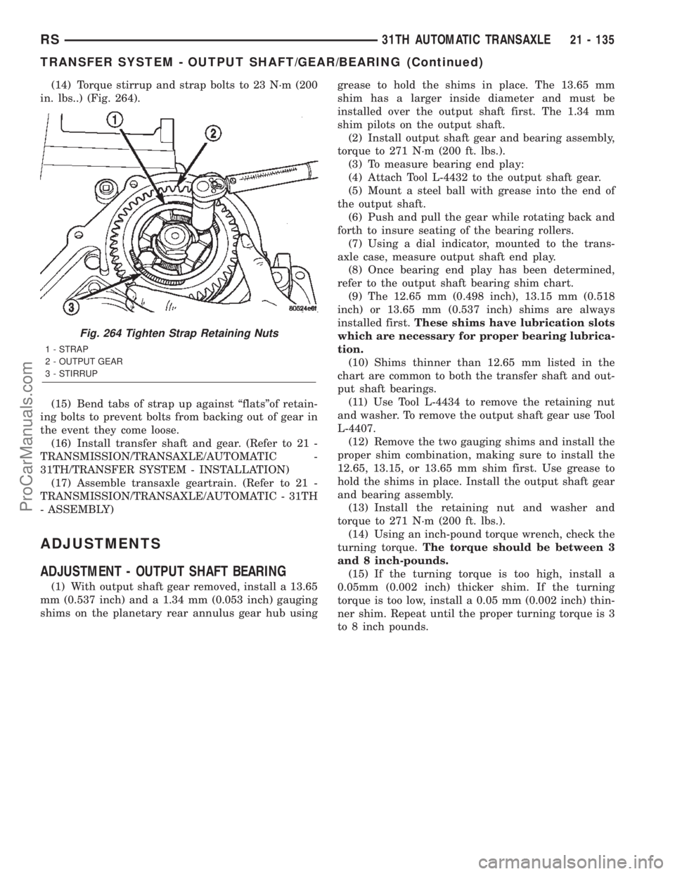
(14) Torque stirrup and strap bolts to 23 N´m (200
in. lbs..) (Fig. 264).
(15) Bend tabs of strap up against ªflatsºof retain-
ing bolts to prevent bolts from backing out of gear in
the event they come loose.
(16) Install transfer shaft and gear. (Refer to 21 -
TRANSMISSION/TRANSAXLE/AUTOMATIC -
31TH/TRANSFER SYSTEM - INSTALLATION)
(17) Assemble transaxle geartrain. (Refer to 21 -
TRANSMISSION/TRANSAXLE/AUTOMATIC - 31TH
- ASSEMBLY)
ADJUSTMENTS
ADJUSTMENT - OUTPUT SHAFT BEARING
(1) With output shaft gear removed, install a 13.65
mm (0.537 inch) and a 1.34 mm (0.053 inch) gauging
shims on the planetary rear annulus gear hub usinggrease to hold the shims in place. The 13.65 mm
shim has a larger inside diameter and must be
installed over the output shaft first. The 1.34 mm
shim pilots on the output shaft.
(2) Install output shaft gear and bearing assembly,
torque to 271 N´m (200 ft. lbs.).
(3) To measure bearing end play:
(4) Attach Tool L-4432 to the output shaft gear.
(5) Mount a steel ball with grease into the end of
the output shaft.
(6) Push and pull the gear while rotating back and
forth to insure seating of the bearing rollers.
(7) Using a dial indicator, mounted to the trans-
axle case, measure output shaft end play.
(8) Once bearing end play has been determined,
refer to the output shaft bearing shim chart.
(9) The 12.65 mm (0.498 inch), 13.15 mm (0.518
inch) or 13.65 mm (0.537 inch) shims are always
installed first.These shims have lubrication slots
which are necessary for proper bearing lubrica-
tion.
(10) Shims thinner than 12.65 mm listed in the
chart are common to both the transfer shaft and out-
put shaft bearings.
(11) Use Tool L-4434 to remove the retaining nut
and washer. To remove the output shaft gear use Tool
L-4407.
(12) Remove the two gauging shims and install the
proper shim combination, making sure to install the
12.65, 13.15, or 13.65 mm shim first. Use grease to
hold the shims in place. Install the output shaft gear
and bearing assembly.
(13) Install the retaining nut and washer and
torque to 271 N´m (200 ft. lbs.).
(14) Using an inch-pound torque wrench, check the
turning torque.The torque should be between 3
and 8 inch-pounds.
(15) If the turning torque is too high, install a
0.05mm (0.002 inch) thicker shim. If the turning
torque is too low, install a 0.05 mm (0.002 inch) thin-
ner shim. Repeat until the proper turning torque is 3
to 8 inch pounds.
Fig. 264 Tighten Strap Retaining Nuts
1 - STRAP
2 - OUTPUT GEAR
3 - STIRRUP
RS31TH AUTOMATIC TRANSAXLE21 - 135
TRANSFER SYSTEM - OUTPUT SHAFT/GEAR/BEARING (Continued)
ProCarManuals.com
Page 1702 of 2399
ADJUSTMENTS
ADJUSTMENT - TRANSFER SHAFT BEARING
(1) Use Tool L-4434 to remove the retaining nut
and washer. Remove the transfer shaft gear using
Tool L-4407.
(2) Install a 2.29 mm (0.090 inch) and a 1.39 mm
(0.055 inch) gauging shims on the transfer shaft
behind the governor support.
(3) Install transfer shaft gear and bearing assem-
bly and torque the nut to 271 N´m (200 ft. lbs.).
(4) To measure bearing end play:Attach Tool
L-4432 to the transfer gear.
(5) Mount a steel ball with grease into the end of
the transfer shaft.
(6) Push and pull the gear while rotating back and
forth to insure seating of the bearing rollers.
(7) Using a dial indicator, measure transfer shaft
end play.
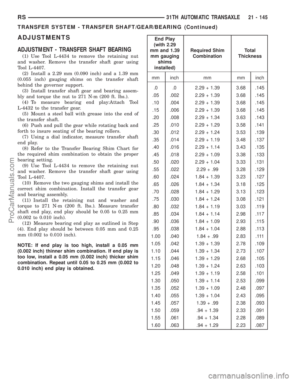
(8) Refer to the Transfer Bearing Shim Chart for
the required shim combination to obtain the proper
bearing setting.
(9) Use Tool L-4434 to remove the retaining nut
and washer. Remove the transfer shaft gear using
Tool L-4407.
(10) Remove the two gauging shims and install the
correct shim combination. Install the transfer gear
and bearing assembly.
(11) Install the retaining nut and washer and
torque to 271 N´m (200 ft. lbs.). Measure transfer
shaft end play, end play should be 0.05 to 0.25 mm
(0.002 to 0.010 inch).
(12) Measure bearing end play as outlined in Step
(4). End play should be between 0.05 mm and 0.25
mm (0.002 to 0.010 inch).
NOTE: If end play is too high, install a 0.05 mm
(0.002 inch) thinner shim combination. If end play is
too low, install a 0.05 mm (0.002 inch) thicker shim
combination. Repeat until 0.05 to 0.25 mm (0.002 to
0.010 inch) end play is obtained.
End Play
(with 2.29
mm and 1.39
mm gauging
shims
installed)Required Shim
CombinationTotal
Thickness
mm inch mm mm inch
.0 .0 2.29 + 1.39 3.68 .145
.05 .002 2.29 + 1.39 3.68 .145
.10 .004 2.29 + 1.39 3.68 .145
.15 .006 2.29 + 1.39 3.68 .145
.20 .008 2.29 + 1.34 3.63 .143
.25 .010 2.29 + 1.29 3.58 .141
.30 .012 2.29 + 1.24 3.53 .139
.35 .014 2.29 + 1.19 3.48 .137
.40 .016 2.29 + 1.14 3.43 .135
.45 .018 2.29 + 1.09 3.38 .133
.50 .020 2.29 + 1.04 3.33 .131
.55 .022 2.29 + .99 3.28 .129
.60 .024 1.84 + 1.39 3.23 .127
.65 .026 1.84 + 1.34 3.18 .125
.70 .028 1.84 + 1.29 3.13 .123
.75 .030 1.84 + 1.24 3.08 .121
.80 .032 1.84 + 1.19 3.03 .119
.85 .034 1.84 + 1.14 2.98 .117
.90 .036 1.84 + 1.09 2.93 .115
.95 .038 1.84 + 1.04 2.88 .113
1.00 .040 1.84 + .99 2.83 .111
1.05 .042 1.39 + 1.39 2.78 .109
1.10 .044 1.39 + 1.34 2.73 .107
1.15 .046 1.39 + 1.29 2.68 .105
1.20 .048 1.39 + 1.24 2.63 .103
1.25 .049 1.39 + 1.19 2.58 .101
1.30 .050 1.39 + 1.14 2.53 .099
1.35 .052 1.39 + 1.09 2.48 .097
1.40 .055 1.39 + 1.04 2.43 .095
1.45 .057 1.39 + .99 2.38 .093
1.50 .059 .94 + 1.39 2.33 .091
1.55 .061 .94 + 1.34 2.28 .089
1.60 .063 .94 + 1.29 2.23 .087
RS31TH AUTOMATIC TRANSAXLE21 - 145
TRANSFER SYSTEM - TRANSFER SHAFT/GEAR/BEARING (Continued)
ProCarManuals.com
Page 1763 of 2399
(47) Install snap ring.
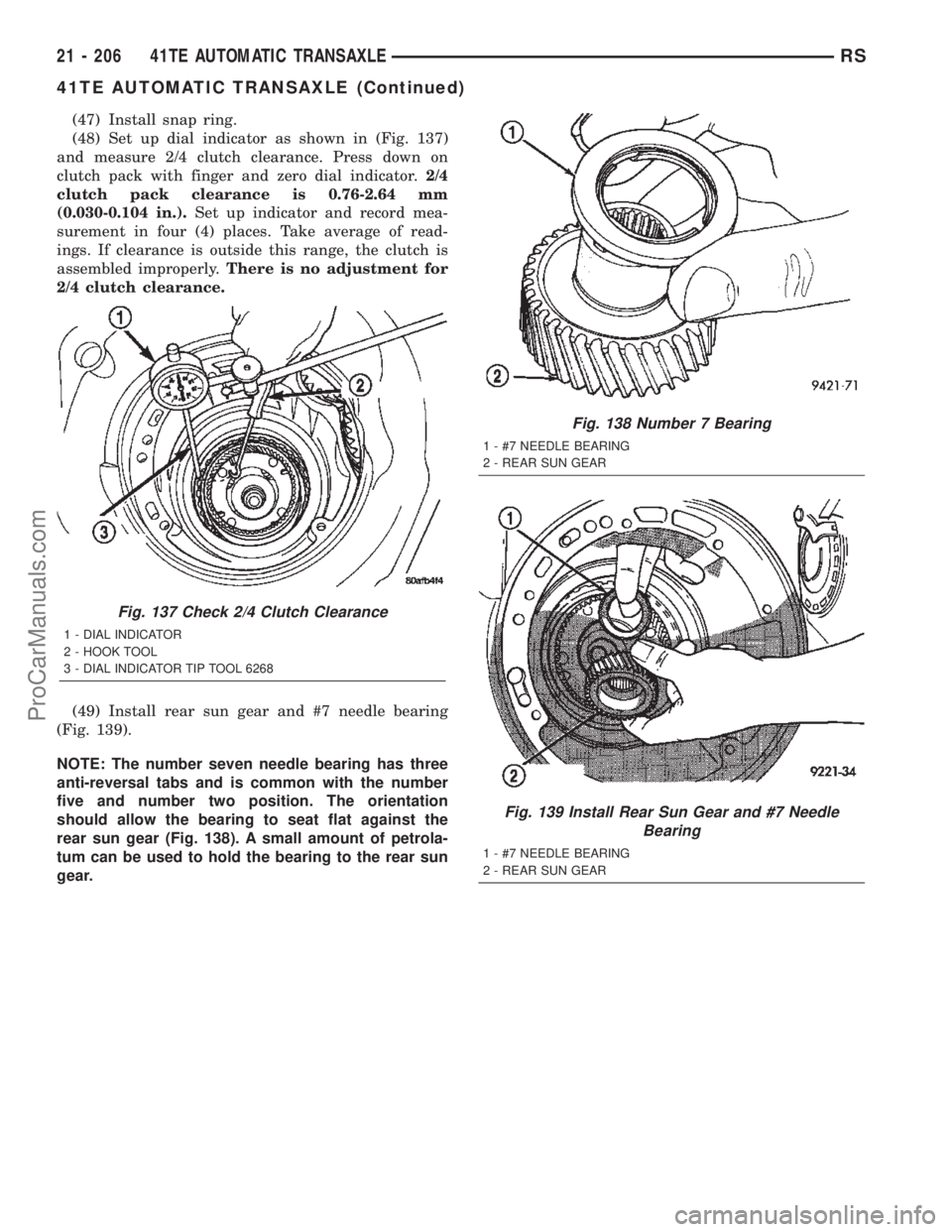
(48) Set up dial indicator as shown in (Fig. 137)
and measure 2/4 clutch clearance. Press down on
clutch pack with finger and zero dial indicator.2/4
clutch pack clearance is 0.76-2.64 mm
(0.030-0.104 in.).Set up indicator and record mea-
surement in four (4) places. Take average of read-
ings. If clearance is outside this range, the clutch is
assembled improperly.There is no adjustment for
2/4 clutch clearance.
(49) Install rear sun gear and #7 needle bearing
(Fig. 139).
NOTE: The number seven needle bearing has three
anti-reversal tabs and is common with the number
five and number two position. The orientation
should allow the bearing to seat flat against the
rear sun gear (Fig. 138). A small amount of petrola-
tum can be used to hold the bearing to the rear sun
gear.
Fig. 137 Check 2/4 Clutch Clearance
1 - DIAL INDICATOR
2 - HOOK TOOL
3 - DIAL INDICATOR TIP TOOL 6268
Fig. 138 Number 7 Bearing
1 - #7 NEEDLE BEARING
2 - REAR SUN GEAR
Fig. 139 Install Rear Sun Gear and #7 Needle
Bearing
1 - #7 NEEDLE BEARING
2 - REAR SUN GEAR
21 - 206 41TE AUTOMATIC TRANSAXLERS
41TE AUTOMATIC TRANSAXLE (Continued)
ProCarManuals.com
Page 1805 of 2399
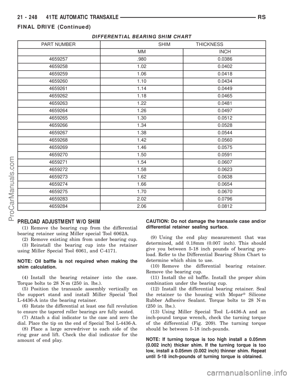
DIFFERENTIAL BEARING SHIM CHART
PART NUMBER SHIM THICKNESS
MM INCH
4659257 .980 0.0386
4659258 1.02 0.0402
4659259 1.06 0.0418
4659260 1.10 0.0434
4659261 1.14 0.0449
4659262 1.18 0.0465
4659263 1.22 0.0481
4659264 1.26 0.0497
4659265 1.30 0.0512
4659266 1.34 0.0528
4659267 1.38 0.0544
4659268 1.42 0.0560
4659269 1.46 0.0575
4659270 1.50 0.0591
4659271 1.54 0.0607
4659272 1.58 0.0623
4659273 1.62 0.0638
4659274 1.66 0.0654
4659275 1.70 0.0670
4659283 2.02 0.0796
4659284 2.06 0.0812
PRELOAD ADJUSTMENT W/O SHIM
(1) Remove the bearing cup from the differential
bearing retainer using Miller special Tool 6062A.
(2) Remove existing shim from under bearing cup.
(3) Reinstall the bearing cup into the retainer
using Miller Special Tool 6061, and C-4171.
NOTE: Oil baffle is not required when making the
shim calculation.
(4) Install the bearing retainer into the case.
Torque bolts to 28 N´m (250 in. lbs.).
(5) Position the transaxle assembly vertically on
the support stand and install Miller Special Tool
L-4436-A into the bearing retainer.
(6)
Rotate the differential at least one full revolution
to ensure the tapered roller bearings are fully seated.
(7)Attach a dial indicator to the case and zero the
dial. Place the tip on the end of Special Tool L-4436-A.
(8) Place a large screwdriver to each side of the
ring gear and lift. Check the dial indicator for the
amount of end play.CAUTION: Do not damage the transaxle case and/or
differential retainer sealing surface.
(9) Using the end play measurement that was
determined, add 0.18mm (0.007 inch). This should
give you between 5-18 inch pounds of bearing pre-
load. Refer to the Differential Bearing Shim Chart to
determine which shim to use.
(10) Remove the differential bearing retainer.
Remove the bearing cup.
(11) Install the oil baffle. Install the proper shim
combination under the bearing cup.
(12) Install the differential bearing retainer. Seal
the retainer to the housing with MopartSilicone
Rubber Adhesive Sealant. Torque bolts to 28 N´m
(250 in. lbs.).
(13) Using Miller Special Tool L-4436-A and an
inch-pound torque wrench, check the turning torque
of the differential (Fig. 209). The turning torque
should be between 5-18 inch-pounds.
NOTE: If turning torque is too high install a 0.05mm
(0.002 inch) thicker shim. If the turning torque is too
low, install a 0.05mm (0.002 inch) thinner shim. Repeat
until 5-18 inch-pounds of turning torque is obtained.
21 - 248 41TE AUTOMATIC TRANSAXLERS
FINAL DRIVE (Continued)
ProCarManuals.com
Page 1915 of 2399

ADJUSTMENT - DIFFERENTIAL SIDE GEAR
END PLAY
Measure side gear end play: Insert feeler gauges
180É apart between differential side gear and thrust
washer as shown in (Fig. 124). Measurement taken
here applies to both sides. Side gear end play should
be between 0.025-0.152 mm (0.001-0.006 in.). If clear-
ance is greater than 0.152 mm (0.006 in.), install a
thicker thrust washer (both sides). If clearance is less
than 0.025 mm (0.001), install a thinner thrust
washer (both sides). Refer to (Fig. 125) for available
side gear shim thicknesses.
If end play measurement indicates a thrust washer
change is necessary, the differential must be disas-
sembled. (Refer to 21 - TRANSMISSION/TRANS-
AXLE/MANUAL/DIFFERENTIAL - DISASSEMBLY)
FLUID
STANDARD PROCEDURE
STANDARD PROCEDURE - FLUID LEVEL
CHECK
NOTE: For proper fluid level check intervals, (Refer
to LUBRICATION & MAINTENANCE/MAINTENANCE
SCHEDULES - DESCRIPTION)
The fluid required in this transaxle is Mopart
ATF+4 (Automatic Transmission FluidÐType 9602).
Use of substitute fluids may result in improper
transaxle operation and/or failure.
(1) Raise vehicle on hoist.(2) Remove transaxle fill plug (Fig. 126).
(3) Inspect fluid level. Fluid should be within 1/8º
below fill hole. Add MopartATF+4 (Automatic Trans-
mission FluidÐType 9602) as neccessary.
(4) Install fill plug, ensuring it is properly seated.
(5) Lower vehicle.
Fig. 124 Side Gear End Play Measurement
1 - FEELER GAUGE
Fig. 125 Available Side Gear Thrust Washers
1 - (PLAIN) 0.79-0.84 mm (0.031-0.033 in.)
2 - ( TRIANGLE) 0.91-0.97 mm (0.036-0.038 in.)
3 - (SQUARE) 1.04-1.10 mm (0.041-0.043 in.)
4 - (DIAMOND) 1.17-1.22 mm (0.046-0.048 in.)
Fig. 126 Transaxle Fill Plug
1 - FILL PLUG
2 - END COVER
21 - 358 T850 MANUAL TRANSAXLERS
DIFFERENTIAL (Continued)
ProCarManuals.com
Page 2068 of 2399
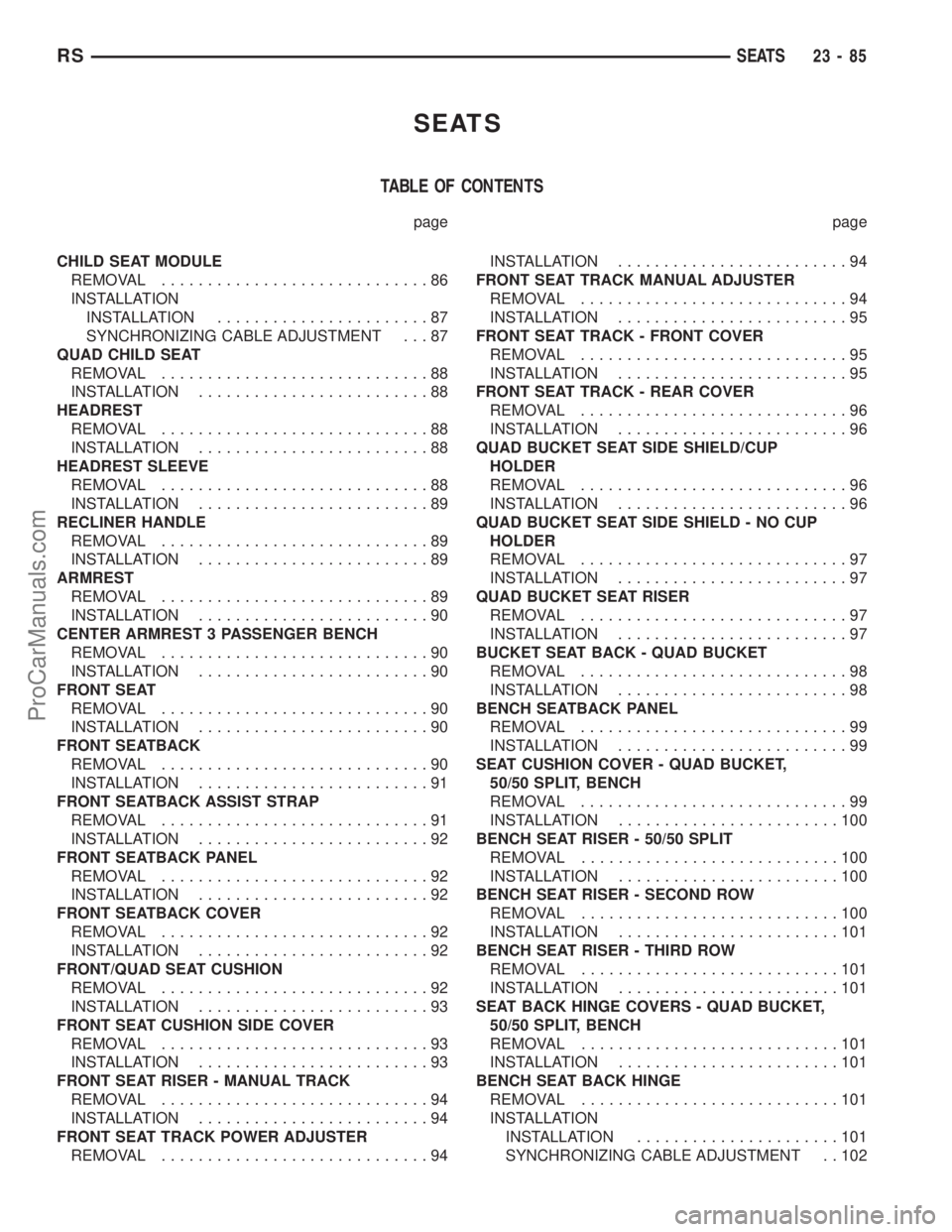
SEATS
TABLE OF CONTENTS
page page
CHILD SEAT MODULE
REMOVAL.............................86
INSTALLATION
INSTALLATION.......................87
SYNCHRONIZING CABLE ADJUSTMENT . . . 87
QUAD CHILD SEAT
REMOVAL.............................88
INSTALLATION.........................88
HEADREST
REMOVAL.............................88
INSTALLATION.........................88
HEADREST SLEEVE
REMOVAL.............................88
INSTALLATION.........................89
RECLINER HANDLE
REMOVAL.............................89
INSTALLATION.........................89
ARMREST
REMOVAL.............................89
INSTALLATION.........................90
CENTER ARMREST 3 PASSENGER BENCH
REMOVAL.............................90
INSTALLATION.........................90
FRONT SEAT
REMOVAL.............................90
INSTALLATION.........................90
FRONT SEATBACK
REMOVAL.............................90
INSTALLATION.........................91
FRONT SEATBACK ASSIST STRAP
REMOVAL.............................91
INSTALLATION.........................92
FRONT SEATBACK PANEL
REMOVAL.............................92
INSTALLATION.........................92
FRONT SEATBACK COVER
REMOVAL.............................92
INSTALLATION.........................92
FRONT/QUAD SEAT CUSHION
REMOVAL.............................92
INSTALLATION.........................93
FRONT SEAT CUSHION SIDE COVER
REMOVAL.............................93
INSTALLATION.........................93
FRONT SEAT RISER - MANUAL TRACK
REMOVAL.............................94
INSTALLATION.........................94
FRONT SEAT TRACK POWER ADJUSTER
REMOVAL.............................94INSTALLATION.........................94
FRONT SEAT TRACK MANUAL ADJUSTER
REMOVAL.............................94
INSTALLATION.........................95
FRONT SEAT TRACK - FRONT COVER
REMOVAL.............................95
INSTALLATION.........................95
FRONT SEAT TRACK - REAR COVER
REMOVAL.............................96
INSTALLATION.........................96
QUAD BUCKET SEAT SIDE SHIELD/CUP
HOLDER
REMOVAL.............................96
INSTALLATION.........................96
QUAD BUCKET SEAT SIDE SHIELD - NO CUP
HOLDER
REMOVAL.............................97
INSTALLATION.........................97
QUAD BUCKET SEAT RISER
REMOVAL.............................97
INSTALLATION.........................97
BUCKET SEAT BACK - QUAD BUCKET
REMOVAL.............................98
INSTALLATION.........................98
BENCH SEATBACK PANEL
REMOVAL.............................99
INSTALLATION.........................99
SEAT CUSHION COVER - QUAD BUCKET,
50/50 SPLIT, BENCH
REMOVAL.............................99
INSTALLATION........................100
BENCH SEAT RISER - 50/50 SPLIT
REMOVAL............................100
INSTALLATION........................100
BENCH SEAT RISER - SECOND ROW
REMOVAL............................100
INSTALLATION........................101
BENCH SEAT RISER - THIRD ROW
REMOVAL............................101
INSTALLATION........................101
SEAT BACK HINGE COVERS - QUAD BUCKET,
50/50 SPLIT, BENCH
REMOVAL............................101
INSTALLATION........................101
BENCH SEAT BACK HINGE
REMOVAL............................101
INSTALLATION
INSTALLATION......................101
SYNCHRONIZING CABLE ADJUSTMENT . . 102
RSSEATS23-85
ProCarManuals.com
Page 2070 of 2399
INSTALLATION
INSTALLATION
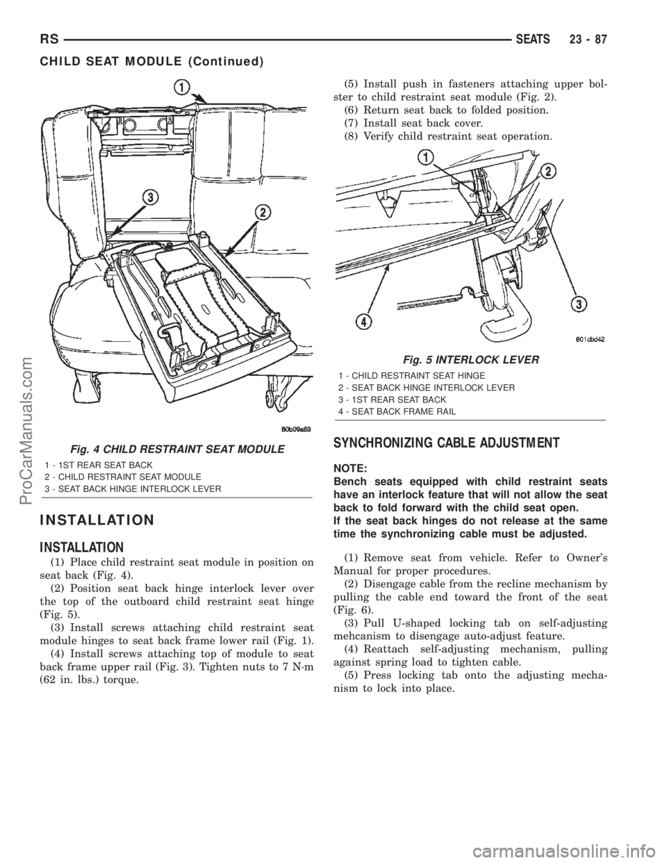
(1) Place child restraint seat module in position on
seat back (Fig. 4).
(2) Position seat back hinge interlock lever over
the top of the outboard child restraint seat hinge
(Fig. 5).
(3) Install screws attaching child restraint seat
module hinges to seat back frame lower rail (Fig. 1).
(4) Install screws attaching top of module to seat
back frame upper rail (Fig. 3). Tighten nuts to 7 N´m
(62 in. lbs.) torque.(5) Install push in fasteners attaching upper bol-
ster to child restraint seat module (Fig. 2).
(6) Return seat back to folded position.
(7) Install seat back cover.
(8) Verify child restraint seat operation.
SYNCHRONIZING CABLE ADJUSTMENT
NOTE:
Bench seats equipped with child restraint seats
have an interlock feature that will not allow the seat
back to fold forward with the child seat open.
If the seat back hinges do not release at the same
time the synchronizing cable must be adjusted.
(1) Remove seat from vehicle. Refer to Owner's
Manual for proper procedures.
(2) Disengage cable from the recline mechanism by
pulling the cable end toward the front of the seat
(Fig. 6).
(3) Pull U-shaped locking tab on self-adjusting
mehcanism to disengage auto-adjust feature.
(4) Reattach self-adjusting mechanism, pulling
against spring load to tighten cable.
(5) Press locking tab onto the adjusting mecha-
nism to lock into place.
Fig. 4 CHILD RESTRAINT SEAT MODULE
1 - 1ST REAR SEAT BACK
2 - CHILD RESTRAINT SEAT MODULE
3 - SEAT BACK HINGE INTERLOCK LEVER
Fig. 5 INTERLOCK LEVER
1 - CHILD RESTRAINT SEAT HINGE
2 - SEAT BACK HINGE INTERLOCK LEVER
3 - 1ST REAR SEAT BACK
4 - SEAT BACK FRAME RAIL
RSSEATS23-87
CHILD SEAT MODULE (Continued)
ProCarManuals.com