cooling CHRYSLER CARAVAN 2002 Service Manual
[x] Cancel search | Manufacturer: CHRYSLER, Model Year: 2002, Model line: CARAVAN, Model: CHRYSLER CARAVAN 2002Pages: 2399, PDF Size: 57.96 MB
Page 2358 of 2399

(12) Remove the heater unit support device from
under the vehicle.
(13) Lower vehicle from lift.
(14) Refill cooling system(Refer to 7 - COOLING -
STANDARD PROCEDURE).
(15) Verify function of the cabin heater.
SUPPLEMENTAL DIESEL
HEATER WIRING
REMOVAL
(1) Elevate vehicle on a lift taking note of the
exhaust tube flexible section.
(2) Unplug connector from vehicle wiring harness
to cabin heater harness.
(3) Unplug connector from cabin heater harness to
dosing pump connector.
(4) Unplug two connectors from cabin heater har-
ness to cabin heater controller connectors.
(5) Remove two wiring harness connectors from
underbody.
(6) Remove two wiring harness connectors from
cabin heater shield.
(7) Carefully route the cabin heater harness to the
left side between the cabin heater unit and the cabin
heater shield.
INSTALLATION
(1) Carefully route the cabin heater harness from
the left side of the cabin heater between the cabin
heater unit and the cabin heater shield.
(2) Install the two wiring harness retaining con-
nectors to the cabin heater shield.
(3) Route the wiring harness along the underside
of the vehicle and install the two wiring harness
retaining connectors.
(4) Plug the two connectors from the cabin heater
harness to the cabin heater controller.
(5) Plug the connector to the cabin heater harness
to the dosing pump connector.
(6) Plug the connector from the vehicle wiring har-
ness to the cabin heater harness.
(7) Lower the vehicle.
(8) Verify function of the cabin heater.
AIR INTAKE PIPE
REMOVAL
NOTE: Heater air intake tube is part of an assembly
that includes the heater cooling intake and return
pipes. If heater air intake tube requires removal or
replacement the entire assembly will require remov-
al/replacement.
(1) Drain cooling system(Refer to 7 - COOLING -
STANDARD PROCEDURE).
(2) Remove clamps from the heater tubes at the
lower heater port and the lower EGR connector
which are located under the hood.
(3) Remove the retaining clamp at the heater air
intake muffler connection(Refer to 24 - HEATING &
AIR CONDITIONING/CABIN HEATER/INLET
MUFFLER - REMOVAL).
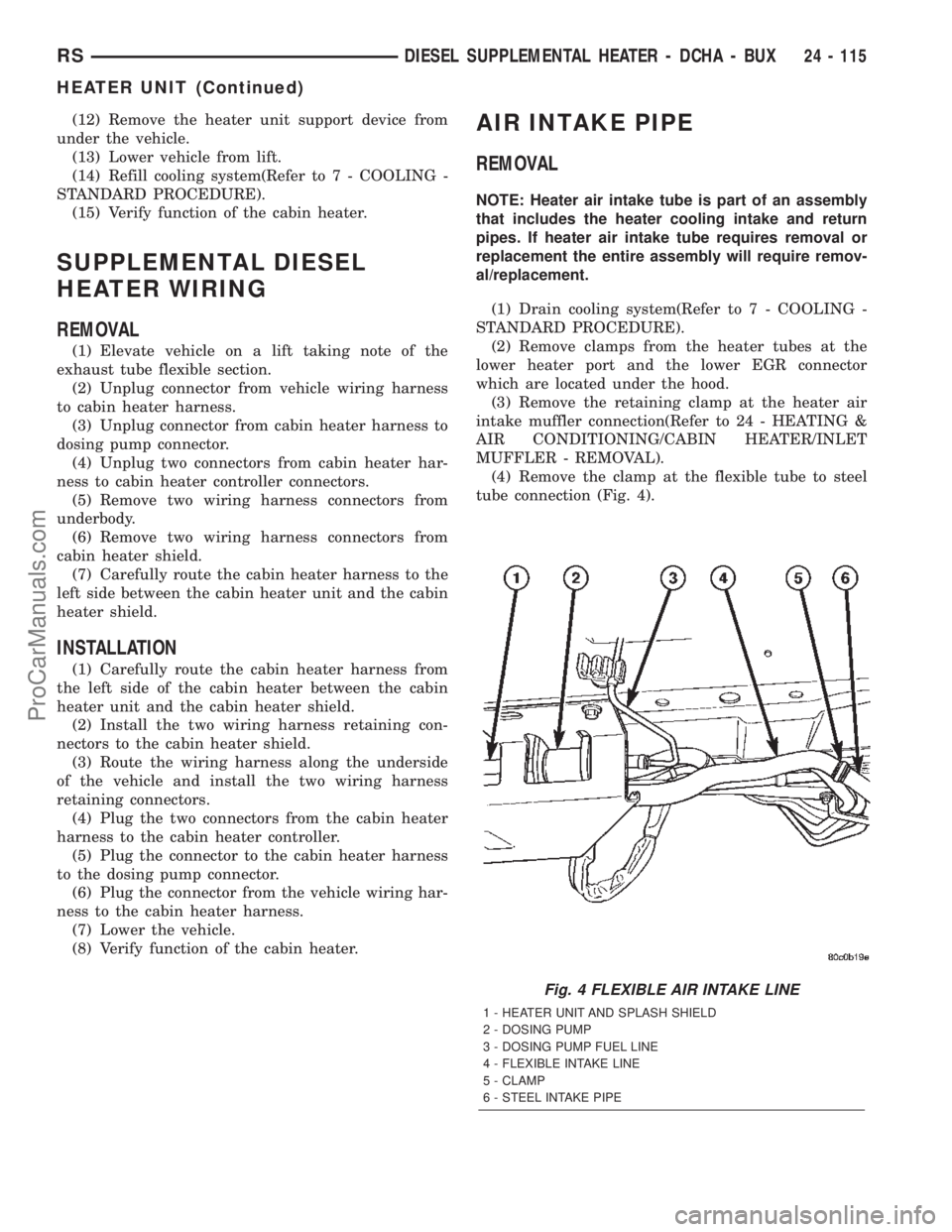
(4) Remove the clamp at the flexible tube to steel
tube connection (Fig. 4).
Fig. 4 FLEXIBLE AIR INTAKE LINE
1 - HEATER UNIT AND SPLASH SHIELD
2 - DOSING PUMP
3 - DOSING PUMP FUEL LINE
4 - FLEXIBLE INTAKE LINE
5 - CLAMP
6 - STEEL INTAKE PIPE
RSDIESEL SUPPLEMENTAL HEATER - DCHA - BUX24 - 115
HEATER UNIT (Continued)
ProCarManuals.com
Page 2359 of 2399

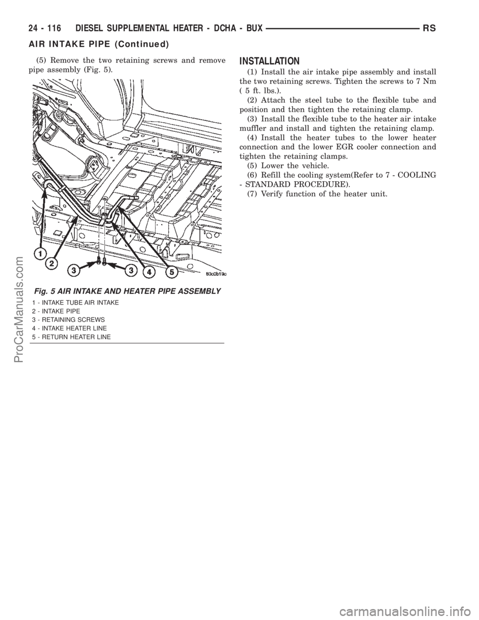
(5) Remove the two retaining screws and remove
pipe assembly (Fig. 5).INSTALLATION
(1) Install the air intake pipe assembly and install
the two retaining screws. Tighten the screws to 7 Nm
( 5 ft. lbs.).
(2) Attach the steel tube to the flexible tube and
position and then tighten the retaining clamp.
(3) Install the flexible tube to the heater air intake
muffler and install and tighten the retaining clamp.
(4) Install the heater tubes to the lower heater
connection and the lower EGR cooler connection and
tighten the retaining clamps.
(5) Lower the vehicle.
(6) Refill the cooling system(Refer to 7 - COOLING
- STANDARD PROCEDURE).
(7) Verify function of the heater unit.
Fig. 5 AIR INTAKE AND HEATER PIPE ASSEMBLY
1 - INTAKE TUBE AIR INTAKE
2 - INTAKE PIPE
3 - RETAINING SCREWS
4 - INTAKE HEATER LINE
5 - RETURN HEATER LINE
24 - 116 DIESEL SUPPLEMENTAL HEATER - DCHA - BUXRS
AIR INTAKE PIPE (Continued)
ProCarManuals.com
Page 2392 of 2399

VALVE COOLER
DESCRIPTION
The EGR valve on this engine uses a cooler to cool
the exhaust gases before the returned to the intake
manifold (Fig. 2). The EGR cooler attaches to the
EGR valve and is cooled with engine coolant.
REMOVAL
(1) Remove engine cover (Refer to 9 - ENGINE -
REMOVAL).
(2) Partially drain cooling system (Refer to 7 -
COOLING/ENGINE/COOLANT - STANDARD PRO-
CEDURE).
(3) Remove front wiper unit (Refer to 8 - ELEC-
TRICAL/WIPERS/WASHERS/WIPER MODULE -
REMOVAL).
(4) Disconnect coolant supply and return lines at
EGR cooler (Fig. 2).
(5) Remove EGR cooler to exhaust manifold retain-
ing bolt (Fig. 2).
(6) Remove EGR cooler to EGR valve retaining
bolts (Fig. 2) and remove cooler.
INSTALLATION
(1) Clean gasket sealing surfaces.
(2) Connect EGR valve cooler and new gasket to
EGR valve (Fig. 2). Torque bolts to 32.4N´m.
(3) Install EGR valve cooler to exhaust manifold
attaching bolt (Fig. 2). Torque bolt to 32.4N´m.
(4) Connect EGR cooler coolant supply and return
hoses to cooler (Fig. 2).
(5) Install front wiper unit (Refer to 8 - ELECTRI-
CAL/WIPERS/WASHERS/WIPER MODULE -
INSTALLATION).
(6) Refill cooling system (Refer to 7 - COOLING/
ENGINE/COOLANT - STANDARD PROCEDURE).
(7) Install engine cover (Refer to 9 - ENGINE -
INSTALLATION).
Fig. 2 EGR COMPONENTS
1 - HOSE CLAMP
2 - COOLANT HOSE
3 - HOSE CLAMP
4 - EGR VALVE RETAINING NUT
5 - E G R VA LV E
6 - COOLANT HOSE
7 - EGR VALVE GASKET
8 - EGR VALVE RETAINING STUDS
9 - EGR COOLER RETAINING BOLT
10 - HOSE CLAMP
11 - HOSE CLAMP
12 - EGR COOLER
13 - EGR COOLER TO EGR VALVE RETAINING BOLT
14 - TURBOCHARGER BRACKET
15 - TURBOCHARGER BRACKET RETAINING BOLT
16 - TURBOCHARGER DOWNPIPE
17 - TURBOCHARGER DOWNPIPE RETAINING NUT
18 - DOWNPIPE GASKET
19 - DOWNPIPE STUD
RGEXHAUST GAS RECIRCULATION25a-5
ProCarManuals.com