engine mount CHRYSLER CARAVAN 2002 Service Manual
[x] Cancel search | Manufacturer: CHRYSLER, Model Year: 2002, Model line: CARAVAN, Model: CHRYSLER CARAVAN 2002Pages: 2399, PDF Size: 57.96 MB
Page 2307 of 2399

(17) Remove the compressor from the engine com-
partment.
NOTE: If a replacement compressor is being
installed, be certain to drain and measure the refrig-
erant oil contained in the removed compressor.
This will determine how much oil the replacement
compressor must contain before it is installed.
(Refer to 24 - HEATING & AIR CONDITIONING/
PLUMBING - FRONT/REFRIGERANT OIL - STAN-
DARD PROCEDURE - REFRIGERANT OIL LEVEL).
REMOVAL - COMPRESSOR MOUNTING
BRACKET - 2.4L ENGINE
(1) Remove the compressor from the mounting
bracket. (Refer to 24 - HEATING & AIR CONDI-
TIONING/PLUMBING/COMPRESSOR - REMOVAL).
(2) Remove the four screws that secure the com-
pressor mounting bracket to the engine (Fig. 3).
(3) Remove the compressor mounting bracket from
the engine.
INSTALLATION
INSTALLATION - COMPRESSOR
NOTE: If a replacement compressor is being
installed, be certain to check the refrigerant oil
level. (Refer to 24 - HEATING & AIR CONDITIONING/
PLUMBING - FRONT/REFRIGERANT OIL - STAN-
DARD PROCEDURE - REFRIGERANT OIL LEVEL).
Use only refrigerant oil of the type recommended
for the compressor in the vehicle.(1) Position the compressor into the engine com-
partment.
(2) On models with the 2.4L engine, loosely install
the four screws that secure the compressor to the
mounting bracket on the engine. Tighten the screws
to 28 N´m (21 ft. lbs.).
(3) On models with the 3.3L and 3.8L engines,
loosely install the three screws and one nut that
secure the compressor to the engine. Tighten each of
the fasteners using the following sequence to 54 N´m
(40 ft. lbs.).
²The upper screw at the rear of the compressor.
²The lower screw at the rear of the compressor.
²The lower screw at the front of the compressor.
²The upper nut at the front of the compressor.
(4) On models with the 3.3L and 3.8L engines only,
engage the retainer on the engine wire harness com-
pressor clutch coil take out with the bracket on the
top of the compressor.
(5) Reconnect the engine wire harness connector
for the compressor clutch coil to the coil pigtail wire
connector on the top of the compressor.
(6) Reinstall the serpentine accessory drive belt
onto the front of the engine. (Refer to 7 - COOLING/
ACCESSORY DRIVE/DRIVE BELTS - 2.4L -
INSTALLATION) or (Refer to 7 - COOLING/ACCES-
SORY DRIVE/DRIVE BELTS - 3.3L/3.8L - INSTAL-
LATION).
(7) Lower the vehicle.
(8) Remove the tape or plugs from the compressor
discharge port and the discharge line fitting.
(9) Lubricate a new rubber O-ring seal with clean
refrigerant oil and install it on the discharge line fit-
ting.
(10) Reconnect the discharge line fitting to the
compressor discharge port.
(11) Install and tighten the nut that secures the
discharge line fitting to the compressor. Tighten the
nut to 23 N´m (17 ft. lbs.).
(12) Remove the tape or plugs from the compressor
suction port and the suction line fitting.
(13) Lubricate a new rubber O-ring seal with clean
refrigerant oil and install it on the suction line fit-
ting.
(14) Reconnect the suction line fitting to the com-
pressor suction port.
(15) Install and tighten the nut that secures the
suction line fitting to the compressor. Tighten the nut
to 23 N´m (17 ft. lbs.).
(16) Reconnect the battery negative cable.
(17) Evacuate the refrigerant system. (Refer to 24
- HEATING & AIR CONDITIONING/PLUMBING -
FRONT/REFRIGERANT - STANDARD PROCE-
DURE - REFRIGERANT SYSTEM EVACUATE).
(18) Charge the refrigerant system. (Refer to 24 -
HEATING & AIR CONDITIONING/PLUMBING -
Fig. 3 Compressor Mounting Bracket - 2.4L Engine
1 - MOUNTING BRACKET
2 - SCREWS (4)
3 - ENGINE
24 - 64 PLUMBING - FRONTRS
COMPRESSOR (Continued)
ProCarManuals.com
Page 2308 of 2399

FRONT/REFRIGERANT - STANDARD PROCE-
DURE - REFRIGERANT SYSTEM CHARGE).
INSTALLATION - COMPRESSOR MOUNTING
BRACKET - 2.4L ENGINE
(1) Position the compressor mounting bracket onto
the engine.
(2) Install and tighten the four screws that secure
the compressor mounting bracket to the engine.
Tighten the screws to 54 N´m (40 ft. lbs.).
(3) Reinstall the compressor onto the mounting
bracket. (Refer to 24 - HEATING & AIR CONDI-
TIONING/PLUMBING/COMPRESSOR - INSTALLA-
TION).
CONDENSER
DESCRIPTION
The condenser is integral to a cooling module
which includes the radiator, the electric cooling fan,
the fan shroud, air seals and an automatic transmis-
sion oil cooler. The cooling module is located in the
air flow in the front of the engine compartment
behind the radiator grille. The condenser cannot be
repaired or adjusted and, if faulty or damaged, it
must be replaced. The condenser may be removed
from the cooling module for service without removing
the cooling module from the vehicle.
OPERATION
The condenser is a heat exchanger that allows the
high-pressure refrigerant gas being discharged by the
compressor to give up its heat to the air passing over
the condenser fins. When the refrigerant gas gives up
its heat, it condenses. When the refrigerant leaves
the condenser, it has become a high-pressure liquid
refrigerant. The volume of air flowing over the con-
denser fins is critical to the proper cooling perfor-
mance of the air conditioning system. Therefore, it is
important that there are no objects placed in front of
the radiator grille openings in the front of the vehicle
or foreign material on the condenser fins that might
obstruct air flow. Also, any factory-installed air seals
or shrouds must be properly reinstalled following
radiator or condenser service.
REMOVAL
WARNING: REFER TO THE APPLICABLE WARN-
INGS AND CAUTIONS FOR THIS SYSTEM BEFORE
PERFORMING THE FOLLOWING OPERATION.
(Refer to 24 - HEATING & AIR CONDITIONING/
PLUMBING - FRONT - WARNING - A/C PLUMBING)
and (Refer to 24 - HEATING & AIR CONDITIONING/
PLUMBING - FRONT - CAUTION - A/C PLUMBING).NOTE: Before removing the condenser, note the
location of each of the radiator and condenser air
seals. These air seals are used to direct air through
the condenser and radiator. The air seals must be
reinstalled in their proper locations in order for the
air conditioning and engine cooling systems to per-
form as designed.
(1) Recover the refrigerant from the refrigerant
system. (Refer to 24 - HEATING & AIR CONDI-
TIONING/PLUMBING - FRONT/REFRIGERANT -
STANDARD PROCEDURE - REFRIGERANT
RECOVERY).
(2) Remove the two large screws that secure the
front fascia and the outboard ends of the radiator
sight shield to the radiator closure panel crossmem-
ber (Fig. 4).
(3) Remove the five small screws that secure the
front fascia grille inserts to the radiator sight shield.
(4) Remove the radiator sight shield from the radi-
ator closure panel crossmember.
(5) Remove the two screws that secure the hood
latch unit to the front of the radiator closure panel
crossmember and move the latch out of the way over
the top of the crossmember. Mark the location of
latch for reinstallation.
(6) Disconnect the hoses from the transmission oil
cooler fittings on the left side of the cooling module.
(Refer to 7 - COOLING/TRANSMISSION/TRANS
COOLER LINES - REMOVAL).
(7) Remove the nut that secures the discharge line
fitting to the condenser on the right side of the cool-
ing module.
Fig. 4 Radiator Sight Shield
1 - LARGE SCREWS (2)
2 - SMALL SCREWS (5)
3 - RADIATOR SIGHT SHIELD
4 - GRILLE INSERTS
5 - FRONT FASCIA
RSPLUMBING - FRONT24-65
COMPRESSOR (Continued)
ProCarManuals.com
Page 2309 of 2399

(8) Disconnect the discharge line fitting from the
condenser inlet port.
(9) Remove the seal from the discharge line fitting
and discard.
(10) Install plugs in, or tape over the opened dis-
charge line fitting and the condenser inlet port.
(11) Remove the nut that secures the liquid line
fitting to the condenser on the right side of the cool-
ing module.
(12) Disconnect the liquid line fitting from the con-
denser outlet port.
(13) Remove the seal from the liquid line fitting
and discard.
(14) Install plugs in, or tape over the opened liquid
line fitting and the condenser outlet port.
(15) Remove the screw that secures the top of the
mounting bracket on each side of the condenser to
the cooling module (Fig. 5).
(16) Lift the condenser, transmission oil cooler, and
mounting brackets as a unit far enough to disengage
the locating pin that secures the mounting brackets
in the lower mount rubber isolators on each side of
the cooling module.
(17) Remove the condenser, transmission oil cooler,
and mounting brackets from the vehicle as a unit.(18) Remove the two screws that secure each
mounting bracket to the sides of the condenser.
(19) Remove the one screw that secures the left
mounting bracket to the side of the transmission oil
cooler.
(20) Remove the left mounting bracket from the
side of the condenser and transmission oil cooler.
(21) Remove the condenser from the right mount-
ing bracket and transmission oil cooler unit.
INSTALLATION
NOTE: If the condenser is being replaced, add 30
milliliters (1 fluid ounce) of refrigerant oil to the
refrigerant system. Use only refrigerant oil of the
type recommended for the compressor in the vehi-
cle.
NOTE: Be certain that each of the radiator and con-
denser air seals are reinstalled in their proper loca-
tions. These air seals are required in order for the
air conditioning and engine cooling systems to per-
form as designed.
(1) Position the condenser to the right mounting
bracket and transmission oil cooler unit.
(2) Position the left mounting bracket onto the side
of the condenser and transmission oil cooler.
(3) Install and tighten the one screw that secures
the left mounting bracket to the side of the transmis-
sion oil cooler. Tighten the screw to 5 N´m (45 in.
lbs.).
(4) Install and tighten the two screws that secure
each mounting bracket to the sides of the condenser.
Tighten the screws to 5 N´m (45 in. lbs.).
(5) Position the condenser, transmission oil cooler,
and mounting brackets into the vehicle as a unit. Be
certain that the locating pins that secure the mount-
ing brackets are engaged in the lower mount rubber
isolators on each side of the cooling module.
NOTE: Verify that the condensor isolators are all
installed and positioned correctly.
(6) Install and tighten the two screws that secure
the top of the mounting bracket on each side of the
condenser to the cooling module. Tighten the screws
to 5 N´m (45 in. lbs.).
(7) Remove the tape or plugs from the condenser
outlet port and the liquid line fitting.
(8) Lubricate a new rubber O-ring seal with clean
refrigerant oil and install it on the liquid line fitting.
(9) Reconnect the liquid line fitting to the con-
denser outlet port on the right side of the cooling
module.
Fig. 5 Condenser Mounting
1 - SCREW (2)
2 - LOWER MOUNT ISOLATOR (2)
3 - CONDENSER
24 - 66 PLUMBING - FRONTRS
CONDENSER (Continued)
ProCarManuals.com
Page 2318 of 2399

ward far enough to disengage the engine compart-
ment ends of the tubes from the dash panel seal.
(14) Remove the heater core tubes and sealing
plate as a unit from beneath the instrument panel.
(15) Use absorbent toweling to clean up any
engine coolant spills from the preceding operation.
REMOVAL - HEATER CORE
WARNING: REFER TO THE APPLICABLE WARN-
INGS AND CAUTIONS FOR THIS SYSTEM BEFORE
PERFORMING THE FOLLOWING OPERATION.
(Refer to 24 - HEATING & AIR CONDITIONING/
PLUMBING FRONT - WARNING - HEATER PLUMB-
ING).
WARNING: ON VEHICLES EQUIPPED WITH AIR-
BAGS, DISABLE THE AIRBAG SYSTEM BEFORE
ATTEMPTING ANY STEERING WHEEL, STEERING
COLUMN, OR INSTRUMENT PANEL COMPONENT
DIAGNOSIS OR SERVICE. DISCONNECT AND ISO-
LATE THE BATTERY NEGATIVE (GROUND) CABLE,
THEN WAIT TWO MINUTES FOR THE AIRBAG SYS-
TEM CAPACITOR TO DISCHARGE BEFORE PER-
FORMING FURTHER DIAGNOSIS OR SERVICE. THIS
IS THE ONLY SURE WAY TO DISABLE THE AIRBAG
SYSTEM. FAILURE TO TAKE THE PROPER PRE-
CAUTIONS COULD RESULT IN ACCIDENTAL AIR-
BAG DEPLOYMENT AND POSSIBLE PERSONAL
INJURY.
(1) Drain the engine cooling system. (Refer to 7 -
COOLING - STANDARD PROCEDURE - COOLING
SYSTEM DRAIN).
(2) Disconnect and isolate the battery negative
cable.
(3) Remove the silencer boot fasteners located
around the base of the lower steering shaft from the
dash panel so that it may be pushed aside.
(4) Remove the brake lamp switch from its mount-
ing bracket. (Refer to 8 - ELECTRICAL/LAMPS/
LIGHTING - EXTERIOR/BRAKE LAMP SWITCH -
REMOVAL).
(5) Disconnect the power brake booster input rod
(push rod) from the pin on the brake pedal arm.
(Refer to 5 - BRAKES - ABS/HYDRAULIC/ME-
CHANICAL/POWER BRAKE BOOSTER - REMOV-
AL).
(6) Remove the three screws that secure the heater
core shield to the left end of the HVAC distribution
housing (Fig. 17).
(7) Pull the heater core shield rearward far enough
to disengage the two location tabs that position the
front of the shield to the receptacles in the two lower
finger formations of the evaporator housing near the
dash panel.(8) Remove the heater core shield from the distri-
bution housing.
(9) Take the proper precautions to protect the car-
peting below the heater core from spilled engine cool-
ant and have absorbent toweling readily available to
mop up any spills.
(10) Remove the screw that secures the heater core
tube sealing plate to the heater core supply and
return ports (Fig. 18).
Fig. 17 Heater Core Shield
1 - HEATER/ AIR CONDITIONER HOUSING
2 - HEATER CORE SHIELD
3 - DISTRIBUTION HOUSING
4 - SCREWS (3)
5 - LOCATION TABS (2)
Fig. 18 Heater Core
1 - SEALING PLATE
2 - SCREW
3 - SCREWS (2)
4 - HEATER CORE
5 - HEATER CORE TUBES
RSPLUMBING - FRONT24-75
HEATER CORE (Continued)
ProCarManuals.com
Page 2319 of 2399

(11) Push both heater core tubes simultaneously
toward the dash panel far enough to disengage their
fittings from the heater core supply and return ports.
(12) Install plugs in, or tape over the opened
heater core tube fittings and both heater core ports.
(13) Use absorbent toweling to mop up any engine
coolant spills from the preceding operation.
(14) Remove the two screws that secure the heater
core mounting plate to the distribution housing.
(15) While pulling the accelerator pedal upward
(Fig. 19) and pushing the brake pedal downward
(Fig. 20) far enough for clearance, pull the heater
core out of the distribution housing.(16) Use absorbent toweling to mop up any engine
coolant spills from the preceding operation. Also, if
the heater core was leaking, use absorbent toweling
and reach into the heater core opening to mop up
any residual engine coolant within the distribution
housing.
INSTALLATION
INSTALLATION- HEATER CORE EXTENSION
TUBES
WARNING: REFER TO THE APPLICABLE WARN-
INGS AND CAUTIONS FOR THIS SYSTEM BEFORE
PERFORMING THE FOLLOWING OPERATION.
(Refer to 24 - HEATING & AIR CONDITIONING/
PLUMBING FRONT - WARNING - HEATER PLUMB-
ING).
WARNING: ON VEHICLES EQUIPPED WITH AIR-
BAGS, DISABLE THE AIRBAG SYSTEM BEFORE
ATTEMPTING ANY STEERING WHEEL, STEERING
COLUMN, OR INSTRUMENT PANEL COMPONENT
DIAGNOSIS OR SERVICE. DISCONNECT AND ISO-
LATE THE BATTERY NEGATIVE (GROUND) CABLE,
THEN WAIT TWO MINUTES FOR THE AIRBAG SYS-
TEM CAPACITOR TO DISCHARGE BEFORE PER-
FORMING FURTHER DIAGNOSIS OR SERVICE. THIS
IS THE ONLY SURE WAY TO DISABLE THE AIRBAG
SYSTEM. FAILURE TO TAKE THE PROPER PRE-
CAUTIONS COULD RESULT IN ACCIDENTAL AIR-
BAG DEPLOYMENT AND POSSIBLE PERSONAL
INJURY.
(1) Remove the plugs or tape from both heater core
tube fittings and both heater core ports.
(2) Position the heater core tubes and sealing plate
as a unit beneath the instrument panel.
(3) Align the engine compartment ends of both
heater core tubes with the openings in the dash
panel seal and push them simultaneously forward
through the seal far enough to engage the heater
core ends of the tubes with the heater core supply
and return ports.
(4) Position both heater core tubes and the sealing
plate simultaneously to the heater core supply and
return ports.
(5) The heater core tubes each have a slot that
must be indexed to a location tab within each of the
heater core ports. Adjust the position of the tubes as
required so that the sealing plate fits flush against
the heater core supply and return ports, which indi-
cates that the tubes are properly indexed.
Fig. 19 Accelerator Pedal
1 - SLIDE HEATER CORE PAST ACCELERATOR PEDAL
Fig. 20 Brake Pedal
1 - SLIDE HEATER CORE PAST BRAKE PEDAL
2 - DEPRESS BRAKE PEDAL
24 - 76 PLUMBING - FRONTRS
HEATER CORE (Continued)
ProCarManuals.com
Page 2320 of 2399
(6) Install and tighten the screw that secures the
heater core tube sealing plate to the heater core sup-
ply and return ports. Tighten the screw to 3 N´m (27
in. lbs.).
(7) Position the heater core shield onto the distri-
bution housing. Be certain that the two location tabs
on the front of the shield are engaged in the recepta-
cles in the two lower finger formations of the evapo-
rator housing near the dash panel.
(8) Install and tighten the three screws that secure
the heater core shield to the left end of the HVAC
distribution housing. Tighten the screws to 2 N´m (17
in. lbs.).
(9) Reinstall the silencer under the driver side end
of the instrument panel. (Refer to 23 - BODY/IN-
STRUMENT PANEL/INSTRUMENT PANEL
SILENCER - INSTALLATION).
(10) Reconnect the heater hoses to the heater hose
tubes. (Refer to 24 - HEATING & AIR CONDITION-
ING/PLUMBING - FRONT/HEATER HOSE -
INSTALLATION).
(11) Reconnect the battery negative cable.
(12) Refill the engine cooling system. (Refer to 7 -
COOLING - STANDARD PROCEDURE - COOLING
SYSTEM REFILL).
INSTALLATION - HEATER CORE
WARNING: REFER TO THE APPLICABLE WARN-
INGS AND CAUTIONS FOR THIS SYSTEM BEFORE
PERFORMING THE FOLLOWING OPERATION.
(Refer to 24 - HEATING & AIR CONDITIONING/
PLUMBING FRONT - WARNING - HEATER PLUMB-
ING).
WARNING: ON VEHICLES EQUIPPED WITH AIR-
BAGS, DISABLE THE AIRBAG SYSTEM BEFORE
ATTEMPTING ANY STEERING WHEEL, STEERING
COLUMN, OR INSTRUMENT PANEL COMPONENT
DIAGNOSIS OR SERVICE. DISCONNECT AND ISO-
LATE THE BATTERY NEGATIVE (GROUND) CABLE,
THEN WAIT TWO MINUTES FOR THE AIRBAG SYS-
TEM CAPACITOR TO DISCHARGE BEFORE PER-
FORMING FURTHER DIAGNOSIS OR SERVICE. THIS
IS THE ONLY SURE WAY TO DISABLE THE AIRBAG
SYSTEM. FAILURE TO TAKE THE PROPER PRE-
CAUTIONS COULD RESULT IN ACCIDENTAL AIR-
BAG DEPLOYMENT AND POSSIBLE PERSONAL
INJURY.(1) While pushing the brake pedal downward and
pulling the accelerator pedal upward far enough for
clearance, slide the heater core into the distribution
housing.
(2) Install and tighten the two screws that secure
the heater core mounting plate to the distribution
housing. Tighten the screws to 2 N´m (17 in. lbs.).
(3) Remove the plugs or tape from the heater core
tube fittings and both heater core ports.
(4) Position both heater core tubes and the sealing
plate simultaneously to the heater core supply and
return ports.
(5) The heater core tubes each have a slot that
must be indexed to a location tab within each of the
heater core ports. Adjust the position of the tubes as
required so that the sealing plate fits flush against
the heater core supply and return ports, which indi-
cates that the tubes are properly indexed.
(6) Install and tighten the screw that secures the
heater core tube sealing plate to the heater core sup-
ply and return ports. Tighten the screw to 3 N´m (27
in. lbs.).
(7) Position the heater core shield onto the distri-
bution housing. Be certain that the two location tabs
on the front of the shield are engaged in the recepta-
cles in the two lower finger formations of the evapo-
rator housing near the dash panel.
(8) Install and tighten the three screws that secure
the heater core shield to the left end of the HVAC
distribution housing. Tighten the screws to 2 N´m (17
in. lbs.).
(9) Reconnect the power brake booster input rod
(push rod) to the pin on the brake pedal arm(Refer to
5 - BRAKES/HYDRAULIC/MECHANICAL/POWER
BRAKE BOOSTER - INSTALLATION).
(10) Reinstall the brake lamp switch into its
mounting bracket(Refer to 8 - ELECTRICAL/LAMPS/
LIGHTING - EXTERIOR/BRAKE LAMP SWITCH -
INSTALLATION).
(11) Reinstall the silencer boot around the base of
the lower steering shaft on the dash panel.
(12) Reconnect the battery negative cable.
(13) Refill the engine cooling system. (Refer to 7 -
COOLING - STANDARD PROCEDURE - COOLING
SYSTEM REFILL).
(14) Operate system for two thermostat cycles to
assure elimination of air in the system.
RSPLUMBING - FRONT24-77
HEATER CORE (Continued)
ProCarManuals.com
Page 2328 of 2399

FRONT/REFRIGERANT - STANDARD PROCE-
DURE - REFRIGERANT SYSTEM EVACUATE).
(17) Charge the refrigerant system. (Refer to 24 -
HEATING & AIR CONDITIONING/PLUMBING -
FRONT/REFRIGERANT - STANDARD PROCE-
DURE - REFRIGERANT SYSTEM CHARGE).
REAR SECTION
(1) Position the rear section of the front liquid line
into the engine compartment.
(2) Remove the tape or plugs from the suction line
and liquid line fittings and both expansion valve
ports.
(3) Lubricate new rubber O-ring seals with clean
refrigerant oil and install them on the suction line
and liquid line fittings.
(4) Reconnect the liquid line and suction line fit-
tings to the expansion valve.
(5) Install and tighten the nut that secures the
suction line and liquid line fittings to the expansion
valve. Tighten the nut to 23 N´m (17 ft. lbs.).
(6) Remove the tape or plugs from the liquid line
rear section fitting for the filter-drier and the filter-
drier outlet port.
(7) Lubricate a new rubber O-ring seal with clean
refrigerant oil and install it on the liquid line fitting.
(8) Reconnect the liquid line fitting to the filter-
drier outlet port on the top of the filter-drier.
(9) Install and tighten the screw that secures the
liquid line fitting to the filter-drier. Tighten the screw
to 2 N´m (16 in. lbs.).
(10) Reinstall the A/C ground strap eyelet terminal
connector onto the weld stud on the top of the right
front strut tower.
(11) Install and tighten the nut that secures the
A/C ground strap to the weld stud. Tighten the nut
to 12 N´m (106 in. lbs.).
(12) Reinstall the A/C pressure transducer onto
the fitting on the front liquid line rear section. (Refer
to 24 - HEATING & AIR CONDITIONING/CON-
TROLS - FRONT/A/C PRESSURE TRANSDUCER -
INSTALLATION).
(13) Reconnect the drain tube to the wiper module
drain on the right side of the engine compartment.
(14) Reinstall the air cleaner housing into the
right side of the engine compartment.
(15) Reconnect the battery negative cable.
(16) If the vehicle is equipped with the optional
rear air conditioner, go to Step 17. If the vehicle does
not have the optional rear air conditioner, go to Step
23.
(17) Raise and support the vehicle.
(18) Remove the tape or plugs from the liquid line
rear section extension fitting and the underbody liq-
uid line fitting.(19) Lubricate a new rubber O-ring seal with clean
refrigerant oil and install it on the underbody liquid
line fitting.
(20) Reconnect the liquid line rear section exten-
sion fitting to the underbody liquid line fitting.
Tighten the fittings to 23 N´m (17 ft. lbs.).
(21) Install a new tie strap just forward of the con-
nections between the underbody plumbing and the
engine compartment plumbing for the rear heater
and air conditioner.
(22) Lower the vehicle.
(23) Evacuate the refrigerant system. (Refer to 24
- HEATING & AIR CONDITIONING/PLUMBING -
FRONT/REFRIGERANT - STANDARD PROCE-
DURE - REFRIGERANT SYSTEM EVACUATE).
(24) Charge the refrigerant system. (Refer to 24 -
HEATING & AIR CONDITIONING/PLUMBING -
FRONT/REFRIGERANT - STANDARD PROCE-
DURE - REFRIGERANT SYSTEM CHARGE).
RECEIVER/DRIER
DESCRIPTION
The filter-drier is mounted in a bracket secured to
the right front strut tower in the engine compart-
ment. The filter-drier is connected between the front
and rear sections of the liquid line between the con-
denser outlet and the evaporator inlet. The filter-
drier cannot be repaired. If the filter-drier is faulty
or damaged, or if the refrigerant system has been
contaminated or left open to the atmosphere for an
indeterminable period, it must be replaced.
OPERATION
The filter-drier performs a filtering action to pre-
vent foreign material in the refrigerant from contam-
inating the expansion valve. A desiccant bag is
mounted inside the filter-drier canister to absorb any
moisture which may have entered and become
trapped within the refrigerant system. In addition,
during periods of high demand air conditioner opera-
tion, the filter-drier acts as a reservoir to store sur-
plus refrigerant. Refrigerant enters the filter-drier as
a high-pressure, low temperature liquid.
REMOVAL
WARNING: REFER TO THE APPLICABLE WARN-
INGS AND CAUTIONS FOR THIS SYSTEM BEFORE
PERFORMING THE FOLLOWING OPERATION.
(Refer to 24 - HEATING & AIR CONDITIONING/
PLUMBING - FRONT - WARNING - A/C PLUMBING)
and (Refer to 24 - HEATING & AIR CONDITIONING/
PLUMBING - FRONT - CAUTION - A/C PLUMBING).
RSPLUMBING - FRONT24-85
LIQUID LINE (Continued)
ProCarManuals.com
Page 2329 of 2399
(1) Recover the refrigerant from the refrigerant
system. (Refer to 24 - HEATING & AIR CONDI-
TIONING/PLUMBING - FRONT/REFRIGERANT -
STANDARD PROCEDURE - REFRIGERANT
RECOVERY).
(2) Remove the air cleaner housing from the right
side of the engine compartment.
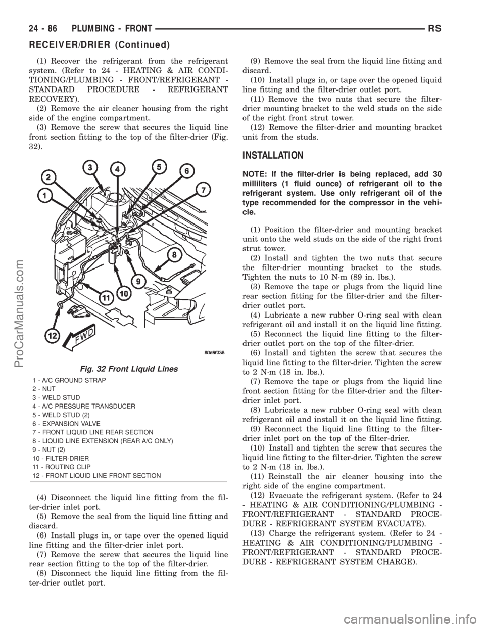
(3) Remove the screw that secures the liquid line
front section fitting to the top of the filter-drier (Fig.
32).
(4) Disconnect the liquid line fitting from the fil-
ter-drier inlet port.
(5) Remove the seal from the liquid line fitting and
discard.
(6) Install plugs in, or tape over the opened liquid
line fitting and the filter-drier inlet port.
(7) Remove the screw that secures the liquid line
rear section fitting to the top of the filter-drier.
(8) Disconnect the liquid line fitting from the fil-
ter-drier outlet port.(9) Remove the seal from the liquid line fitting and
discard.
(10) Install plugs in, or tape over the opened liquid
line fitting and the filter-drier outlet port.
(11) Remove the two nuts that secure the filter-
drier mounting bracket to the weld studs on the side
of the right front strut tower.
(12) Remove the filter-drier and mounting bracket
unit from the studs.
INSTALLATION
NOTE: If the filter-drier is being replaced, add 30
milliliters (1 fluid ounce) of refrigerant oil to the
refrigerant system. Use only refrigerant oil of the
type recommended for the compressor in the vehi-
cle.
(1) Position the filter-drier and mounting bracket
unit onto the weld studs on the side of the right front
strut tower.
(2) Install and tighten the two nuts that secure
the filter-drier mounting bracket to the studs.
Tighten the nuts to 10 N´m (89 in. lbs.).
(3) Remove the tape or plugs from the liquid line
rear section fitting for the filter-drier and the filter-
drier outlet port.
(4) Lubricate a new rubber O-ring seal with clean
refrigerant oil and install it on the liquid line fitting.
(5) Reconnect the liquid line fitting to the filter-
drier outlet port on the top of the filter-drier.
(6) Install and tighten the screw that secures the
liquid line fitting to the filter-drier. Tighten the screw
to 2 N´m (18 in. lbs.).
(7) Remove the tape or plugs from the liquid line
front section fitting for the filter-drier and the filter-
drier inlet port.
(8) Lubricate a new rubber O-ring seal with clean
refrigerant oil and install it on the liquid line fitting.
(9) Reconnect the liquid line fitting to the filter-
drier inlet port on the top of the filter-drier.
(10) Install and tighten the screw that secures the
liquid line fitting to the filter-drier. Tighten the screw
to 2 N´m (18 in. lbs.).
(11) Reinstall the air cleaner housing into the
right side of the engine compartment.
(12) Evacuate the refrigerant system. (Refer to 24
- HEATING & AIR CONDITIONING/PLUMBING -
FRONT/REFRIGERANT - STANDARD PROCE-
DURE - REFRIGERANT SYSTEM EVACUATE).
(13) Charge the refrigerant system. (Refer to 24 -
HEATING & AIR CONDITIONING/PLUMBING -
FRONT/REFRIGERANT - STANDARD PROCE-
DURE - REFRIGERANT SYSTEM CHARGE).
Fig. 32 Front Liquid Lines
1 - A/C GROUND STRAP
2 - NUT
3 - WELD STUD
4 - A/C PRESSURE TRANSDUCER
5 - WELD STUD (2)
6 - EXPANSION VALVE
7 - FRONT LIQUID LINE REAR SECTION
8 - LIQUID LINE EXTENSION (REAR A/C ONLY)
9 - NUT (2)
10 - FILTER-DRIER
11 - ROUTING CLIP
12 - FRONT LIQUID LINE FRONT SECTION
24 - 86 PLUMBING - FRONTRS
RECEIVER/DRIER (Continued)
ProCarManuals.com
Page 2330 of 2399

REFRIGERANT
DESCRIPTION
The refrigerant used in this air conditioning sys-
tem is a HydroFluoroCarbon (HFC), type R-134a.
Unlike R-12, which is a ChloroFluoroCarbon (CFC),
R-134a refrigerant does not contain ozone-depleting
chlorine. R-134a refrigerant is a non-toxic, non-flam-
mable, clear, and colorless liquefied gas. Even though
R-134a does not contain chlorine, it must be
reclaimed and recycled just like CFC-type refriger-
ants. This is because R-134a is a greenhouse gas and
can contribute to global warming.
OPERATION
R-134a refrigerant is not compatible with R-12
refrigerant in an air conditioning system. Even a
small amount of R-12 added to an R-134a refrigerant
system will cause compressor failure, refrigerant oil
sludge or poor air conditioning system performance.
In addition, the PolyAlkylene Glycol (PAG) synthetic
refrigerant oils used in an R-134a refrigerant system
are not compatible with the mineral-based refriger-
ant oils used in an R-12 refrigerant system. R-134a
refrigerant system service ports, service tool couplers
and refrigerant dispensing bottles have all been
designed with unique fittings to ensure that an
R-134a system is not accidentally contaminated with
the wrong refrigerant (R-12). There are also labels
posted in the engine compartment of the vehicle and
on the compressor identifying to service technicians
that the air conditioning system is equipped with
R-134a.
DIAGNOSIS AND TESTING
DIAGNOSIS AND TESTING - REFRIGERANT
SYSTEM CHARGE LEVEL
WARNING: REFER TO THE APPLICABLE WARN-
INGS AND CAUTIONS FOR THIS SYSTEM BEFORE
PERFORMING THE FOLLOWING OPERATION.
(Refer to 24 - HEATING & AIR CONDITIONING/
PLUMBING - FRONT - WARNING - A/C PLUMBING)
and (Refer to 24 - HEATING & AIR CONDITIONING/
PLUMBING - FRONT - CAUTION - A/C PLUMBING).
NOTE: The proper amount of R-134a refrigerant for
the refrigerant system in this model is:
²Single or Dual Zone (Front Unit Only) - 0.96
kilograms (2.13 pounds or 34 ounces)
²Three Zone (Front and Rear Units) - 1.31 kilo-
grams (2.88 pounds or 46 ounces)The procedure that follows should be used to deter-
mine whether the refrigerant system contains the
proper refrigerant charge. Symptoms of an improper
refrigerant charge (low) include: poor air conditioner
performance, fog emitted from the air conditioner
outlets, a hissing sound from the expansion valve/
evaporator area. There are two different methods
with which the refrigerant charge level may be
tested:
²Using a DRBIIItscan tool, a thermocouple and
the Charge Determination Chart (Fig. 33). Refer to
the appropriate diagnostic information.
²Using a manifold gauge set, a thermocouple and
the Charge Determination Chart (Fig. 33).
A temperature probe is required to measure liquid
line temperature. The clamp-on, Type K thermocou-
ple temperature probe used in this procedure is
available through the DaimlerChrysler Professional
Service Equipment (PSE) program. This probe (PSE
#66-324-0014 or #80PK-1A) is compatible with tem-
perature-measuring instruments that accept Type K
thermocouples, and have a miniature connector
input. Other temperature probes are available
through aftermarket sources; however, all references
in this procedure will reflect the use of the probe
made available through the PSE program.
In order to use the temperature probe, a digital
thermometer will also be required. If a digital ther-
mometer is not available, an adapter is available
through the PSE program that will convert any stan-
dard digital multimeter into a digital thermometer.
This adapter is designed to accept any standard Type
K thermocouple. If a digital multimeter is not avail-
able, this tool is also available through the PSE pro-
gram.
NOTE: When connecting the service equipment
couplings to the refrigerant system service ports,
be certain that the valve of each coupling is fully
closed. This will reduce the amount of effort
required to make the connection.
(1) Remove the caps from the refrigerant system
service ports and attach a manifold gauge set or a
R-134a refrigerant recovery/recycling/charging sta-
tion that meets SAE Standard J2210 to the refriger-
ant system.
(2) Attach a clamp-on thermocouple to the liquid
line. The thermocouple must be placed as close to the
A/C pressure transducer as possible to accurately
observe liquid line temperature.
(3) Bring the refrigerant system up to operating
temperature and pressure. This is done by allowing
the engine to run at idle under the following condi-
tions for five minutes.
(a) Front windows are open.
(b) Transaxle in Park.
RSPLUMBING - FRONT24-87
ProCarManuals.com
Page 2332 of 2399

location of a possible refrigerant leak, the exact leak
location should be confirmed with an electronic leak
detector prior to component repair or replacement.
An electronic leak detector designed for R-134a
refrigerant is recommended for locating and confirm-
ing refrigerant system leaks. See the operating
instructions supplied by the equipment manufacturer
for proper care and use of this equipment.
To detect a leak in the refrigerant system, perform
one of the following procedures as indicated by the
results of the refrigerant system charge level test.
SYSTEM EMPTY
(1) Evacuate the refrigerant system. (Refer to 24 -
HEATING & AIR CONDITIONING/PLUMBING -
FRONT/REFRIGERANT - STANDARD PROCE-
DURE - REFRIGERANT SYSTEM EVACUATE).
(2) Connect and dispense 0.283 kilograms (0.625
pounds or 10 ounces) of R-134a refrigerant into the
evacuated refrigerant system. (Refer to 24 - HEAT-
ING & AIR CONDITIONING/PLUMBING - FRONT/
REFRIGERANT - STANDARD PROCEDURE -
REFRIGERANT SYSTEM CHARGE).
(3) Proceed to the SYSTEM LOW procedures.
SYSTEM LOW
(1) Position the vehicle in a wind-free work area.
This will aid in detecting small leaks.
(2) Bring the refrigerant system up to operating
temperature and pressure. This is done by allowing
the engine to run at idle under the following condi-
tions for five minutes, then turning the engine off.
(a) Front windows are open.
(b) Rear air conditioner Off (if equipped).
(c) Transaxle in Park.
(d) Front heater-A/C controls set to outside air,
panel mode, blower high, and compressor engaged.
(3) Wait five to seven minutes and, with the
engine not running, use a electronic R-134a leak
detector and search for leaks. Because R-134a refrig-
erant is heavier than air, the leak detector probe
should be moved slowly along the bottom side of all
refrigerant lines, connector fittings and components.
(4) To inspect an evaporator for leaks, insert the
electronic leak detector probe into a floor outlet or
the recirculation air intake.
DIAGNOSIS AND TESTING - REFRIGERANT
SYSTEM CHARGE LEVEL 2.5L DIESEL
WARNING: REFER TO THE APPLICABLE WARN-
INGS AND CAUTIONS FOR THIS SYSTEM BEFORE
PERFORMING THE FOLLOWING OPERATION.
(Refer to 24 - HEATING & AIR CONDITIONING/
PLUMBING - FRONT - WARNING - A/C PLUMBING)and (Refer to 24 - HEATING & AIR CONDITIONING/
PLUMBING - FRONT - CAUTION - A/C PLUMBING).
NOTE: The proper amount of R-134a refrigerant for
the refrigerant system in this model is:
²Single or Dual Zone (Front Unit Only - 2.5L Die-
sel) ± 0.91 kilograms (2.00 pounds or 32 ounces)
²Single or Dual Zone (Front Unit Only) - 0.96
kilograms (2.13 pounds or 34 ounces)
²Three Zone (Front and Rear Units) - 1.31 kilo-
grams (2.88 pounds or 46 ounces)
The procedure that follows should be used to deter-
mine whether the refrigerant system contains the
proper refrigerant charge. Symptoms of an improper
refrigerant charge (low) include: poor air conditioner
performance, fog emitted from the air conditioner
outlets, a hissing sound from the expansion valve/
evaporator area. There are two different methods
with which the refrigerant charge level may be
tested:
²Using a DRBIIItscan tool, a thermocouple and
the Charge Determination Chart (Fig. 34). Refer to
the appropriate diagnostic information.
²Using a manifold gauge set, a thermocouple and
the Charge Determination Chart (Fig. 34).
A temperature probe is required to measure liquid
line temperature. The clamp-on, Type K thermocou-
ple temperature probe used in this procedure is
available through the DaimlerChrysler Professional
Service Equipment (PSE) program. This probe (PSE
#66-324-0014 or #80PK-1A) is compatible with tem-
perature-measuring instruments that accept Type K
thermocouples, and have a miniature connector
input. Other temperature probes are available
through aftermarket sources; however, all references
in this procedure will reflect the use of the probe
made available through the PSE program.
In order to use the temperature probe, a digital
thermometer will also be required. If a digital ther-
mometer is not available, an adapter is available
through the PSE program that will convert any stan-
dard digital multimeter into a digital thermometer.
This adapter is designed to accept any standard Type
K thermocouple. If a digital multimeter is not avail-
able, this tool is also available through the PSE pro-
gram.
NOTE: When connecting the service equipment
couplings to the refrigerant system service ports,
be certain that the valve of each coupling is fully
closed. This will reduce the amount of effort
required to make the connection.
(1) Remove the caps from the refrigerant system
service ports and attach a manifold gauge set or a
R-134a refrigerant recovery/recycling/charging sta-
RSPLUMBING - FRONT24-89
REFRIGERANT (Continued)
ProCarManuals.com