reset CHRYSLER CARAVAN 2002 Workshop Manual
[x] Cancel search | Manufacturer: CHRYSLER, Model Year: 2002, Model line: CARAVAN, Model: CHRYSLER CARAVAN 2002Pages: 2399, PDF Size: 57.96 MB
Page 596 of 2399

The switch is secured to the back of the seat cush-
ion side shield with two screws. However, the control
knobs for the seat switch unit must be removed
before the seat switch can be removed from the side
shield.
The power seat switch cannot be repaired. If one
switch is damaged or faulty, the entire power seat
switch unit must be replaced.
OPERATION
When a power seat switch control knob or knobs
are actuated, a battery feed and a ground path are
applied through the switch contacts to the power seat
track or recliner adjuster motor. The selected
adjuster motor operates to move the seat track or
recliner through its drive unit in the selected direc-
tion until the switch is released, or until the travel
limit of the adjuster is reached. When the switch is
moved in the opposite direction, the battery feed and
ground path to the motor are reversed through the
switch contacts. This causes the adjuster motor to
run in the opposite direction.
No power seat switch should be held applied in any
direction after the adjuster has reached its travel
limit. The power seat adjuster motors each contain a
self-resetting circuit breaker to protect them from
overload. However, consecutive or frequent resetting
of the circuit breaker must not be allowed to con-
tinue, or the motor may be damaged. See the owner's
manual in the vehicle glove box for more information
on the power seat switch functions and the seat
adjusting procedures.
DIAGNOSIS AND TESTING - DRIVER SEAT
SWITCH
(1) Remove the power seat switch, refer to the
Switch Removal and Installation procedures in this
section.
(2) Using an ohmmeter, check pin #1 of the power
seat switch connector for continuity to ground. It
should be present, If OK go to Step3,IfNOTOK
repair the open ground circuit as required.
(3) Using an voltmeter, check pin #5 of the power
seat switch connector for approx. 12v. It should be
present, If OK go to Step4,IfNOTOKrepair the
open voltage supply circuit as required.
(4) Using an ohmmeter, verify the Seat Switch
Continuity Test table, using the seat switch connec-
tor (Fig. 3). If there is no continuity at any of the
switch positions, replace the power seat switch.
DRIVER SEAT SWITCH CONTINUITY TEST
TABLE
SWITCH
POSITIONCONTINUITY BETWEEN
PINS
DRIVER
OFF PIN5&4
PIN5&3
PIN5&2
PIN5&10
PIN5&9
PIN5&8
PIN5&7
PIN5&6
FRONT RISER
UPPIN5&6
PIN1&9
FRONT RISER
DOWNPIN5&9
PIN1&6
CENTER
SWITCH
FORWARDPIN5&3
PIN1&10
CENTER
SWITCH
REARWARDPIN5&10
PIN3&1
REAR RISER UP PIN5&7
PIN1&8
REAR RISER
DOWNPIN5&8
PIN1&7
RECLINER UP PIN5&2
PIN4&1
RECLINER
DOWNPIN5&4
PIN2&1
REMOVAL
(1) Disconnect and isolate the battery negative
cable.
(2) On models equipped with the eight-way power
seat, using a push pin remover or another suitable
wide flat-bladed tool, gently pry the power seat and
power recliner switch knobs off of the switch levers
(Fig. 4).
Fig. 3 Seat Switch Pin Call-Out
RSPOWER SEAT SYSTEM8N-55
DRIVER SEAT SWITCH (Continued)
ProCarManuals.com
Page 598 of 2399

See the owner's manual in the vehicle glove box for
more information on the features, use and operation
of the memory switch.
DIAGNOSIS AND TESTING - MEMORY SWITCH
(1) Remove the memory set switch from the driv-
ers door panel (Refer to 8 - ELECTRICAL/POWER
SEATS/MEMORY SET SWITCH - REMOVAL).
(2) Using an ohmmeter, check for continuity on the
memory select switch MUX circuit between the body
control module C2 electrical connector and the mem-
ory switch connector. Continuity should be present, If
OK go to Step 3, If NOT OK repair the open or
shorted MUX circuit as required.
(3) Using an ohmmeter, check for continuity on the
memory select switch RETURN circuit between the
body control module C2 electrical connector and the
memory switch connector. Continuity should be
present, If OK go to Step 4, If NOT OK repair the
open or shorted RETURN circuit as required.
(4) Using an ohmmeter, test the resistances of the
memory switch in each switch position. See the Mem-
ory Switch Test Table. If OK, refer toDiagnosis and
Testing Memory Systemin this section. If not OK,
replace the faulty memory set switch.
MEMORY SWITCH TEST TABLE
MEMORY
SWITCH
POSITIONRESISTANCE
BETWEEN
PINSRESISTANCE
RANGE
(OHMS)
NEUTRAL 1&2 24650 5%
(24.65 k)
MEMORY 1 1&2 6850 5%
(6.85 k)
MEMORY 2 1&2 2100 5%
(2.10 k)
SET 1&2 4490 5%
(4.49 k)
REMOVAL
(1) Disconnect and isolate the battery negative
cable.
(2) Remove the front door trim panel switch bezel
from the driver side front door. Using a thin flat-
bladed pry tool, gently pry the switch bezel away
from the drivers door trim panel.
(3) Disconnect the memory switch wire harness
connector from the memory switch.
(4) Remove the two screws that secure the memory
switch to the back of the driver side front door trim
panel switch bezel.
(5) Remove the memory switch.
INSTALLATION
(1) Position the memory switch and install and
tighten the two screws that secure the memory
switch to the back of the driver side front door trim
panel switch bezel. Tighten the screws to 2.2 N´m (20
in. lbs.).
(2) Reconnect the memory switch wire harness
connector to the memory switch.
(3) Install the trim panel switch bezel onto the
driver side front door.
(4) Reconnect the battery negative cable.
PASSENGER SEAT SWITCH
DESCRIPTION
Vehicles equipped with power seats utilize a ten-
way power seat switch. This ten-way power seat
switch features two knobs ganged together on the
outboard seat cushion side shield.
The switch is secured to the back of the seat cush-
ion side shield with two screws. However, the control
knobs for the seat switch unit must be removed
before the seat switch can be removed from the side
shield.
The power seat switch cannot be repaired. If one
switch is damaged or faulty, the entire power seat
switch unit must be replaced.
OPERATION
When a power seat switch control knob or knobs
are actuated, a battery feed and a ground path are
applied through the switch contacts to the power seat
track or recliner adjuster motor. The selected
adjuster motor operates to move the seat track or
recliner through its drive unit in the selected direc-
tion until the switch is released, or until the travel
limit of the adjuster is reached. When the switch is
moved in the opposite direction, the battery feed and
ground path to the motor are reversed through the
switch contacts. This causes the adjuster motor to
run in the opposite direction.
No power seat switch should be held applied in any
direction after the adjuster has reached its travel
limit. The power seat adjuster motors each contain a
self-resetting circuit breaker to protect them from
overload. However, consecutive or frequent resetting
of the circuit breaker must not be allowed to con-
tinue, or the motor may be damaged. See the owner's
manual in the vehicle glove box for more information
on the power seat switch functions and the seat
adjusting procedures.
RSPOWER SEAT SYSTEM8N-57
MEMORY SET SWITCH (Continued)
ProCarManuals.com
Page 601 of 2399
DRIVER POWER SEAT TRACK
DESCRIPTION
The eight-way power seat option includes a electri-
cally operated power seat track located under each
front seat. The left side power seat track also pro-
vides the mounting location for the body control mod-
ule on this vehicle. The power seat circuit breakers
are mounted on the rear of each power seat track,
just behind the seat rear trim panel. The lower half
of the power seat track is secured to the floor panel
via four studs and nuts that must be accessed from
the underside of the vehicle. Four bolts secure the
bottom of the seat cushion pan to the upper half of
the power seat track unit. Four additional bolts
secure the seat back frame to the power seat track
unit.
The power seat track unit includes four reversible
electric motors that are secured to the upper half of
the track unit. Each motor moves the seat adjuster
through a combination of worm-drive gearboxes and
screw-type drive units. Each of the four power seat
track motors used on models equipped with the
optional memory system incorporates a position
potentiometer integral to the motor assembly, which
electronically monitors the motor position. This
enables the memory system to function by referenc-
ing the motor positions programmed into the memory
seat/mirror module.
The front and rear of the seat are operated by two
separate vertical adjustment motors. These motors
can be operated independently of each other, tilting
the entire seat assembly forward or rearward; or,
they can be operated in unison by selecting the
proper power seat switch functions, which will raise
or lower the entire seat assembly. A third motor is
the horizontal adjustment motor, which moves the
seat track in the forward and rearward directions.
The forth motor is the recliner adjustment motor,
which moves the seat back in the forward and rear-
ward directions.
The power seat track unit cannot be repaired, and
is serviced only as a complete unit. If any component
in this unit is faulty or damaged, the entire power
seat track unit must be replaced.
OPERATION
When a power seat switch control knob or knobs
are actuated, a battery feed and a ground path are
applied through the switch contacts to the power seat
track or recliner adjuster motor. The selected
adjuster motor operates to move the seat track or
recliner through its drive unit in the selected direc-
tion until the switch is released, or until the travel
limit of the adjuster is reached. When the switch is
moved in the opposite direction, the battery feed andground path to the motor are reversed through the
switch contacts. This causes the adjuster motor to
run in the opposite direction.
No power seat switch should be held applied in any
direction after the adjuster has reached its travel
limit. The power seat adjuster motors each contain a
self-resetting circuit breaker to protect them from
overload. However, consecutive or frequent resetting
of the circuit breaker must not be allowed to con-
tinue, or the motor may be damaged.
See the owner's manual in the vehicle glove box for
more information on the power seat switch functions
and the seat adjusting procedures.
DIAGNOSIS AND TESTING - DRIVER POWER
SEAT TRACK
WARNING: SOME VEHICLES ARE EQUIPPED WITH
SEATBACK MOUNTED AIRBAGS. BEFORE
ATTEMPTING TO DIAGNOSE OR SERVICE ANY
SEAT OR POWER SEAT SYSTEM COMPONENT
YOU MUST FIRST DISCONNECT AND ISOLATE THE
BATTERY NEGATIVE CABLE. THEN WAIT TWO MIN-
UTES FOR THE SYSTEM CAPACITOR TO DIS-
CHARGE BEFORE FURTHER SYSTEM SERVICE.
THIS IS THE ONLY SURE WAY TO DISABLE THE
AIRBAG SYSTEM. FAILURE TO DO SO COULD
RESULT IN ACCIDENTAL AIRBAG DEPLOYMENT
AND POSSIBLE PERSONAL INJURY.
Actuate the power seat switch to move all three
power seat track adjusters in each direction. The
power seat track adjusters should move in each of
the selected directions. If a power seat track adjuster
fails to operate in only one direction, move the
adjuster a short distance in the opposite direction
and test again to be certain that the adjuster is not
at its travel limit. If the power seat track adjuster
still fails to operate in only one direction, refer to
Diagnosis and Testing Power Seat Switchin this
section. If the power seat track adjuster fails to oper-
ate in more than one direction, perform the following
tests. For complete circuit diagrams, refer toWiring
Diagrams.
TESTING POWER SEAT TRACK MOTORS
(1) Check the power seat circuit breaker under the
seat. If OK, go to Step 2. If not OK, replace the
faulty power seat circuit breaker.
(2) Check for battery voltage at the power seat cir-
cuit breaker under the seat. If OK, go to Step 3. If
not OK, repair the open fused B(+) circuit to the fuse
in the Intelligent Power Module as required.
(3) Remove the outboard seat cushion side shield
from the seat. Disconnect the seat wire harness con-
nector from the power seat switch connector recepta-
8N - 60 POWER SEAT SYSTEMRS
ProCarManuals.com
Page 603 of 2399
The power seat track unit cannot be repaired, and
is serviced only as a complete unit. If any component
in this unit is faulty or damaged, the entire power
seat track unit must be replaced.
OPERATION
When a power seat switch control knob or knobs
are actuated, a battery feed and a ground path are
applied through the switch contacts to the power seat
track or recliner adjuster motor. The selected
adjuster motor operates to move the seat track or
recliner through its drive unit in the selected direc-
tion until the switch is released, or until the travel
limit of the adjuster is reached. When the switch is
moved in the opposite direction, the battery feed and
ground path to the motor are reversed through the
switch contacts. This causes the adjuster motor to
run in the opposite direction.
No power seat switch should be held applied in any
direction after the adjuster has reached its travel
limit. The power seat adjuster motors each contain a
self-resetting circuit breaker to protect them from
overload. However, consecutive or frequent resetting
of the circuit breaker must not be allowed to con-
tinue, or the motor may be damaged.
See the owner's manual in the vehicle glove box for
more information on the power seat switch functions
and the seat adjusting procedures.
DIAGNOSIS AND TESTING - POWER SEAT
TRACK
WARNING: SOME VEHICLES ARE EQUIPPED WITH
SEATBACK MOUNTED AIRBAGS. BEFORE
ATTEMPTING TO DIAGNOSE OR SERVICE ANY
SEAT OR POWER SEAT SYSTEM COMPONENT
YOU MUST FIRST DISCONNECT AND ISOLATE THE
BATTERY NEGATIVE CABLE. THEN WAIT TWO MIN-
UTES FOR THE SYSTEM CAPACITOR TO DIS-
CHARGE BEFORE FURTHER SYSTEM SERVICE.
THIS IS THE ONLY SURE WAY TO DISABLE THE
AIRBAG SYSTEM. FAILURE TO DO SO COULD
RESULT IN ACCIDENTAL AIRBAG DEPLOYMENT
AND POSSIBLE PERSONAL INJURY.
Actuate the power seat switch to move all three
power seat track adjusters in each direction. The
power seat track adjusters should move in each of
the selected directions. If a power seat track adjuster
fails to operate in only one direction, move the
adjuster a short distance in the opposite direction
and test again to be certain that the adjuster is notat its travel limit. If the power seat track adjuster
still fails to operate in only one direction, refer to
Diagnosis and Testing Power Seat Switchin this
section. If the power seat track adjuster fails to oper-
ate in more than one direction, perform the following
tests. For complete circuit diagrams, refer toWiring
Diagrams.
(1) Check the power seat circuit breaker under the
seat. If OK, go to Step 2. If not OK, replace the
faulty power seat circuit breaker.
(2) Check for battery voltage at the power seat cir-
cuit breaker under the seat. If OK, go to Step 3. If
not OK, repair the open fused B(+) circuit to the fuse
in the Intelligent Power Module as required.
(3) Remove the outboard seat cushion side shield
from the seat. Disconnect the seat wire harness con-
nector from the power seat switch connector recepta-
cle. Check for battery voltage at the fused B(+)
circuit cavity of the power seat wire harness connec-
tor for the power seat switch. If OK, go to Step 4. If
not OK, repair the open fused B(+) circuit to the
power seat circuit breaker under the seat as
required.
(4) Check for continuity between the ground cir-
cuit cavity of the power seat wire harness connector
for the power seat switch and a good ground. There
should be continuity. If OK, go to Step 5. If not OK,
repair the open ground circuit to ground as required.
(5) Test the power seat switch. Refer toDiagnosis
and Testing Power Seat Switchin this section. If
the switch tests OK, test the circuits of the power
seat wire harness between the inoperative power seat
track adjuster motor and the power seat switch for
shorts or opens. If the circuits check OK, replace the
faulty power seat track unit. If the circuits are not
OK, repair the power seat wire harness as required.
REMOVAL
WARNING: SOME VEHICLES ARE EQUIPPED WITH
SEATBACK MOUNTED AIRBAGS. BEFORE
ATTEMPTING TO DIAGNOSE OR SERVICE ANY
SEAT OR POWER SEAT SYSTEM COMPONENT
YOU MUST FIRST DISCONNECT AND ISOLATE THE
BATTERY NEGATIVE CABLE. THEN WAIT TWO MIN-
UTES FOR THE SYSTEM CAPACITOR TO DIS-
CHARGE BEFORE FURTHER SYSTEM SERVICE.
THIS IS THE ONLY SURE WAY TO DISABLE THE
AIRBAG SYSTEM. FAILURE TO DO SO COULD
RESULT IN ACCIDENTAL AIRBAG DEPLOYMENT
AND POSSIBLE PERSONAL INJURY.
8N - 62 POWER SEAT SYSTEMRS
PASSENGER POWER SEAT TRACK (Continued)
ProCarManuals.com
Page 1196 of 2399
8W-97 POWER DISTRIBUTION SYSTEM
TABLE OF CONTENTS
page page
POWER DISTRIBUTION SYSTEM
DESCRIPTION..........................1
OPERATION............................1
SPECIAL TOOLS
POWER DISTRIBUTION SYSTEMS.........2
ACCESSORY RELAY
DESCRIPTION..........................2
OPERATION............................2
DIAGNOSIS AND TESTING
DIAGNOSIS & TESTING - ACCESSORY
RELAY...............................2
REMOVAL.............................3
INSTALLATION..........................3
INTEGRATED POWER MODULE
DESCRIPTION..........................3OPERATION............................3
REMOVAL.............................4
INSTALLATION..........................4
IOD FUSE
DESCRIPTION..........................4
OPERATION............................5
REMOVAL.............................5
INSTALLATION..........................5
POWER OUTLET
DESCRIPTION..........................5
OPERATION............................5
DIAGNOSIS AND TESTING
DIAGNOSIS & TESTING - POWER OUTLET . . 5
REMOVAL.............................6
INSTALLATION..........................6
POWER DISTRIBUTION
SYSTEM
DESCRIPTION
This group covers the various standard and
optional power distribution components used on this
model. The power distribution system for this vehicle
consists of the following components:
²Integrated Power Module (IPM)
²Front Control Module (FCM)
²Power Outlets
Refer to Wiring Diagrams for complete circuit sche-
matics.
The power distribution system also incorporates
various types of circuit control and protection fea-
tures, including:
²Automatic resetting circuit breakers
²Blade-type fuses
²Bus bars
²Cartridge fuses
²Circuit splice blocks
²Flashers
²Fusible links
²Relays
Following are general descriptions of the major
components in the power distribution system. See the
owner's manual in the vehicle glove box for more
information on the features and use of all of the
power distribution system components.
OPERATION
The power distribution system for this vehicle is
designed to provide safe, reliable, and centralized dis-
tribution points for the electrical current required to
operate all of the many standard and optional facto-
ry-installed electrical and electronic powertrain,
chassis, safety, security, comfort and convenience sys-
tems. At the same time, the power distribution sys-
tem was designed to provide ready access to these
electrical distribution points for the vehicle techni-
cian to use when conducting diagnosis and repair of
faulty circuits. The power distribution system can
also prove useful for the sourcing of additional elec-
trical circuits that may be required to provide the
electrical current needed to operate many accessories
that the vehicle owner may choose to have installed
in the aftermarket.
RS8W-97 POWER DISTRIBUTION SYSTEM8W-97-1
ProCarManuals.com
Page 1468 of 2399
FUEL INJECTION
OPERATION
OPERATION - INJECTION SYSTEM
All engines used in this section have a sequential
Multi-Port Electronic Fuel Injection system. The MPI
system is computer regulated and provides precise
air/fuel ratios for all driving conditions. The Power-
train Control Module (PCM) operates the fuel injec-
tion system.
The PCM regulates:
²Ignition timing
²Air/fuel ratio
²Emission control devices
²Cooling fan
²Charging system
²Idle speed
²Vehicle speed control
Various sensors provide the inputs necessary for
the PCM to correctly operate these systems. In addi-
tion to the sensors, various switches also provide
inputs to the PCM.
The PCM can adapt its programming to meet
changing operating conditions.
Fuel is injected into the intake port above the
intake valve in precise metered amounts through
electrically operated injectors. The PCM fires the
injectors in a specific sequence. Under most operat-
ing conditions, the PCM maintains an air fuel ratio
of 14.7 parts air to 1 part fuel by constantly adjust-
ing injector pulse width. Injector pulse width is the
length of time the injector is open.
The PCM adjusts injector pulse width by opening
and closing the ground path to the injector. Engine
RPM (speed) and manifold absolute pressure (air
density) are theprimaryinputs that determine
injector pulse width.
OPERATION - MODES OF OPERATION
As input signals to the PCM change, the PCM
adjusts its response to output devices. For example,
the PCM must calculate a different injector pulse
width and ignition timing for idle than it does for
Wide Open Throttle (WOT). There are several differ-
ent modes of operation that determine how the PCM
responds to the various input signals.
There are two different areas of operation, OPEN
LOOP and CLOSED LOOP.
During OPEN LOOP modes the PCM receives
input signals and responds according to preset PCM
programming. Inputs from the upstream and down-
stream heated oxygen sensors are not monitored dur-
ing OPEN LOOP modes, except for heated oxygensensor diagnostics (they are checked for shorted con-
ditions at all times).
During CLOSED LOOP modes the PCM monitors
the inputs from the upstream and downstream
heated oxygen sensors. The upstream heated oxygen
sensor input tells the PCM if the calculated injector
pulse width resulted in the ideal air-fuel ratio of 14.7
to one. By monitoring the exhaust oxygen content
through the upstream heated oxygen sensor, the
PCM can fine tune injector pulse width. Fine tuning
injector pulse width allows the PCM to achieve opti-
mum fuel economy combined with low emissions.
For the PCM to enter CLOSED LOOP operation,
the following must occur:
(1) Engine coolant temperature must be over 35ÉF.
²If the coolant is over 35ÉF the PCM will wait 38
seconds.
²If the coolant is over 50ÉF the PCM will wait 15
seconds.
²If the coolant is over 167ÉF the PCM will wait 3
seconds.
(2) For other temperatures the PCM will interpo-
late the correct waiting time.
(3) O2 sensor must read either greater than 0.745
volts or less than 0.29 volt.
(4) The multi-port fuel injection systems has the
following modes of operation:
²Ignition switch ON (Zero RPM)
²Engine start-up
²Engine warm-up
²Cruise
²Idle
²Acceleration
²Deceleration
²Wide Open Throttle
²Ignition switch OFF
(5) The engine start-up (crank), engine warm-up,
deceleration with fuel shutoff and wide open throttle
modes are OPEN LOOP modes. Under most operat-
ing conditions, the acceleration, deceleration (with
A/C on), idle and cruise modes,with the engine at
operating temperatureare CLOSED LOOP modes.
IGNITION SWITCH ON (ZERO RPM) MODE
When the ignition switch activates the fuel injec-
tion system, the following actions occur:
²The PCM monitors the engine coolant tempera-
ture sensor and throttle position sensor input. The
PCM determines basic fuel injector pulse width from
this input.
²The PCM determines atmospheric air pressure
from the MAP sensor input to modify injector pulse
width.
When the key is in the ON position and the engine
is not running (zero rpm), the Auto Shutdown (ASD)
and fuel pump relays de-energize after approximately
RSFUEL INJECTION14-17
ProCarManuals.com
Page 1470 of 2399

The PCM compares the upstream and downstream
heated oxygen sensor inputs to measure catalytic con-
vertor efficiency. If the catalyst efficiency drops below
the minimum acceptable percentage, the PCM stores a
diagnostic trouble code in memory, after 2 trips.
During certain idle conditions, the PCM may enter
a variable idle speed strategy. During variable idle
speed strategy the PCM adjusts engine speed based
on the following inputs.
²A/C sense
²Battery voltage
²Battery temperature or Calculated Battery Tem-
perature
²Engine coolant temperature
²Engine run time
²Inlet/Intake air temperature
²Vehicle mileage
ACCELERATION MODE
This is a CLOSED LOOP mode. The PCM recog-
nizes an abrupt increase in Throttle Position sensor
output voltage or MAP sensor output voltage as a
demand for increased engine output and vehicle
acceleration. The PCM increases injector pulse width
in response to increased fuel demand.
²Wide Open Throttle-open loop
DECELERATION MODE
This is a CLOSED LOOP mode. During decelera-
tion the following inputs are received by the PCM:
²A/C sense
²Battery voltage
²Inlet/Intake air temperature
²Engine coolant temperature
²Crankshaft position (engine speed)
²Exhaust gas oxygen content (upstream heated
oxygen sensor)
²Knock sensor
²Manifold absolute pressure
²Throttle position sensor
²IAC motor (solenoid) control changes in response
to MAP sensor feedback
The PCM may receive a closed throttle input from
the Throttle Position Sensor (TPS) when it senses an
abrupt decrease in manifold pressure. This indicates a
hard deceleration (Open Loop). In response, the PCM
may momentarily turn off the injectors. This helps
improve fuel economy, emissions and engine braking.
WIDE-OPEN-THROTTLE MODE
This is an OPEN LOOP mode. During wide-open-
throttle operation, the following inputs are used by
the PCM:
²Inlet/Intake air temperature
²Engine coolant temperature
²Engine speed
²Knock sensor²Manifold absolute pressure
²Throttle position
When the PCM senses a wide-open-throttle condi-
tion through the Throttle Position Sensor (TPS) it de-
energizes the A/C compressor clutch relay. This
disables the air conditioning system and disables
EGR (if equipped).
The PCM adjusts injector pulse width to supply a
predetermined amount of additional fuel, based on
MAP and RPM.
IGNITION SWITCH OFF MODE
When the operator turns the ignition switch to the
OFF position, the following occurs:
²All outputs are turned off, unless 02 Heater
Monitor test is being run. Refer to the Emission sec-
tion for On-Board Diagnostics.
²No inputs are monitored except for the heated
oxygen sensors. The PCM monitors the heating ele-
ments in the oxygen sensors and then shuts down.
FUEL CORRECTION or ADAPTIVE MEMORIES
DESCRIPTION
In Open Loop, the PCM changes pulse width with-
out feedback from the O2 Sensors. Once the engine
warms up to approximately 30 to 35É F, the PCM
goes into closed loopShort Term Correctionand
utilizes feedback from the O2 Sensors. Closed loop
Long Term Adaptive Memoryis maintained above
170É to 190É F unless the PCM senses wide open
throttle. At that time the PCM returns to Open Loop
operation.
OPERATION
Short Term
The first fuel correction program that begins func-
tioning is the short term fuel correction. This system
corrects fuel delivery in direct proportion to the read-
ings from the Upstream O2 Sensor.
The PCM monitors the air/fuel ratio by using the
input voltage from the O2 Sensor. When the voltage
reaches its preset high or low limit, the PCM begins
to add or remove fuel until the sensor reaches its
switch point. The short term corrections then begin.
The PCM makes a series of quick changes in the
injector pulse-width until the O2 Sensor reaches its
opposite preset limit or switch point. The process
then repeats itself in the opposite direction.
Short term fuel correction will keep increasing or
decreasing injector pulse-width based upon the
upstream O2 Sensor input. The maximum range of
authority for short term memory is 25% (+/-) of base
pulse-width. Short term is violated and is lost when
ignition is turned OFF.
RSFUEL INJECTION14-19
FUEL INJECTION (Continued)
ProCarManuals.com
Page 1661 of 2399

ADJUSTMENTS
GEARSHIFT CABLE ADJUSTMENT
Lift and rotate the gearshift hand lever into the
park (P) gate position and remove the ignition key.
This confirms the shift lever is in the gated park (P)
position.
After confirming the park gate position, turn the
ignition switch . If the starter will operate, the park
gate position is correct. Move the shift lever into the
neutral (N) position. If the starter will operate in this
position, the linkage is properly adjusted. If the
starter fails to operate in either position, linkage
adjustment is required.
(1) Park the vehicle on level ground and set the
parking brake.
(2) Place the gearshift lever in park (P) gate posi-
tion and remove key.
(3) Loosen the cable adjustment screw at the
transaxle operating lever (Fig. 181).
(4) Pull the transaxle operating lever fully forward
to the park detent position.
(5) Release the park brake, then rock the vehicle
to assure it is in park lock. Reset the park brake.
(6) Tighten the cable adjustment screw to 8 N´m
(70 in. lbs.). Gearshift cable should now be properly
adjusted.
(7) Verify PRNDL indicator still displays the corre-
sponding gear completely. If not, readjustment of
PRNDL may be required.
(8) Check adjustment by using the preceding pro-
cedure.
GOVERNOR
DESCRIPTION
The governor assembly is fastened to the transaxle
transfer shaft. It consists of a governor body, weight,
valve, and shaft.
OPERATION
The governor meters hydraulic pressure, and this
metered pressure is used to signal the transmission
when it is time for a shift to occur. It does this by
balancing governor pressure on one side of a shift
valve, and throttle pressure on the other. When gov-
ernor pressure increases far enough to overcome the
throttle pressure on the valve, a shift occurs.
With the gearshift selector in a forward driving
range, line pressure flows from the manual valve and
down to the governor valve. When the output shaft
starts to rotate with vehicle motion, the governor
weight assembly will start to move outward due to
centrifugal force. As the weight is moved outward, it
will pull the valve with it until the land of the valve
uncovers the line pressure port. As the port begins to
become uncovered, governor pressure is metered. As
the vehicle's speed continues to increase, the weight
assembly will be at a point at which governor pres-
sure is acting on the left side of the reaction area of
the valve. This produces sufficient force to compress
the spring and allow the outer weight to move out
against the outer governor body retaining ring. At a
very high speed, the governor valve will be opened as
far as possible. In this condition, it is possible for
governor pressure to meet, but not to exceed, line
pressure. Generally governor pressure ranges from
0-100 psi from idle to maximum speed, and rises pro-
portionally with the increase in output shaft speed.
Governor pressure and throttle pressure are acting
upon the shift valves to determine when a shift will
occur. Governor pressure is a direct indication of road
speed, and throttle pressure is an indication of
engine load. When both parameters have been met
by the throttle and governor pressures, an upshift or
downshift will occur.
CLEANING
Thoroughly clean all the governor parts in a suit-
able cleaning solution but do not use any type of
caustic cleaning agents.
The governor weight components and the governor
valve, must slide freely in their bores when clean and
dry. Minor surface scratches and burrs can be
smoothed with crocus cloth.
INSPECTION
The aluminum governor valve and outer weight
have a hard coating on them. Check condition of this
Fig. 181 Gearshift Cable Adjustment
1 - SHIFT CABLE ADJUSTMENT
2 - SHIFT CABLE
21 - 104 31TH AUTOMATIC TRANSAXLERS
ProCarManuals.com
Page 1811 of 2399
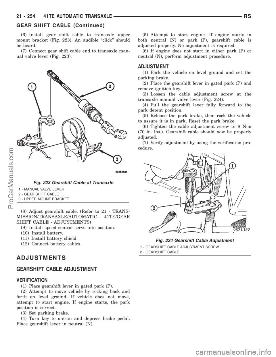
(6) Install gear shift cable to transaxle upper
mount bracket (Fig. 223). An audible ªclickº should
be heard.
(7) Connect gear shift cable end to transaxle man-
ual valve lever (Fig. 223).
(8) Adjust gearshift cable. (Refer to 21 - TRANS-
MISSION/TRANSAXLE/AUTOMATIC - 41TE/GEAR
SHIFT CABLE - ADJUSTMENTS)
(9) Install speed control servo into position.
(10) Install battery.
(11) Install battery shield.
(12) Connect battery cables.
ADJUSTMENTS
GEARSHIFT CABLE ADJUSTMENT
VERIFICATION
(1) Place gearshift lever in gated park (P).
(2) Attempt to move vehicle by rocking back and
forth on level ground. If vehicle does not move,
attempt to start engine. If engine starts, the park
position is correct.
(3) Set parking brake.
(4) Turn key to on/run and depress brake pedal.
Place gearshift lever in neutral (N).(5) Attempt to start engine. If engine starts in
both neutral (N) or park (P), gearshift cable is
adjusted properly. No adjustment is required.
(6) If engine does not start in either park (P) or
neutral (N), perform adjustment procedure.
ADJUSTMENT
(1) Park the vehicle on level ground and set the
parking brake.
(2) Place the gearshift lever in gated park (P) and
remove ignition key.
(3) Loosen the cable adjustment screw at the
transaxle manual valve lever (Fig. 224).
(4) Pull the gearshift lever fully forward to the
park detent position.
(5) Release the park brake, then rock the vehicle
to assure it is in park. Reset the park brake.
(6) Tighten the cable adjustment screw to 8 N´m
(70 in. lbs.). Gearshift cable should now be properly
adjusted.
(7) Verify adjustment by using the verification pro-
cedure.
Fig. 223 Gearshift Cable at Transaxle
1 - MANUAL VALVE LEVER
2 - GEAR SHIFT CABLE
3 - UPPER MOUNT BRACKET
Fig. 224 Gearshift Cable Adjustment
1 - GEARSHIFT CABLE ADJUSTMENT SCREW
2 - GEARSHIFT CABLE
21 - 254 41TE AUTOMATIC TRANSAXLERS
GEAR SHIFT CABLE (Continued)
ProCarManuals.com
Page 1848 of 2399
TRANSMISSION CONTROL
RELAY
DESCRIPTION
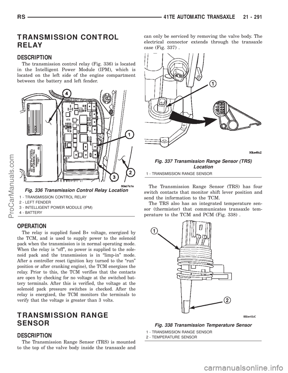
The transmission control relay (Fig. 336) is located
in the Intelligent Power Module (IPM), which is
located on the left side of the engine compartment
between the battery and left fender.
OPERATION
The relay is supplied fused B+ voltage, energized by
the TCM, and is used to supply power to the solenoid
pack when the transmission is in normal operating mode.
When the relay is ªoffº, no power is supplied to the sole-
noid pack and the transmission is in ªlimp-inº mode.
After a controller reset (ignition key turned to the ªrunº
position or after cranking engine), the TCM energizes the
relay. Prior to this, the TCM verifies that the contacts
are open by checking for no voltage at the switched bat-
tery terminals. After this is verified, the voltage at the
solenoid pack pressure switches is checked. After the
relay is energized, the TCM monitors the terminals to
verify that the voltage is greater than 3 volts.
TRANSMISSION RANGE
SENSOR
DESCRIPTION
The Transmission Range Sensor (TRS) is mounted
to the top of the valve body inside the transaxle andcan only be serviced by removing the valve body. The
electrical connector extends through the transaxle
case (Fig. 337) .
The Transmission Range Sensor (TRS) has four
switch contacts that monitor shift lever position and
send the information to the TCM.
The TRS also has an integrated temperature sen-
sor (thermistor) that communicates transaxle tem-
perature to the TCM and PCM (Fig. 338) .
Fig. 336 Transmission Control Relay Location
1 - TRANSMISSION CONTROL RELAY
2 - LEFT FENDER
3 - INTELLIGENT POWER MODULE (IPM)
4 - BATTERY
Fig. 337 Transmission Range Sensor (TRS)
Location
1 - TRANSMISSION RANGE SENSOR
Fig. 338 Transmission Temperature Sensor
1 - TRANSMISSION RANGE SENSOR
2 - TEMPERATURE SENSOR
RS41TE AUTOMATIC TRANSAXLE21 - 291
ProCarManuals.com