reset CHRYSLER CARAVAN 2002 Workshop Manual
[x] Cancel search | Manufacturer: CHRYSLER, Model Year: 2002, Model line: CARAVAN, Model: CHRYSLER CARAVAN 2002Pages: 2399, PDF Size: 57.96 MB
Page 1970 of 2399

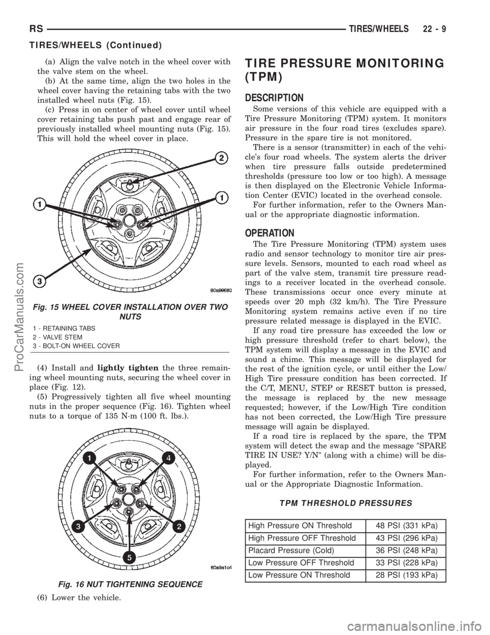
(a) Align the valve notch in the wheel cover with
the valve stem on the wheel.
(b) At the same time, align the two holes in the
wheel cover having the retaining tabs with the two
installed wheel nuts (Fig. 15).
(c) Press in on center of wheel cover until wheel
cover retaining tabs push past and engage rear of
previously installed wheel mounting nuts (Fig. 15).
This will hold the wheel cover in place.
(4) Install andlightly tightenthe three remain-
ing wheel mounting nuts, securing the wheel cover in
place (Fig. 12).
(5) Progressively tighten all five wheel mounting
nuts in the proper sequence (Fig. 16). Tighten wheel
nuts to a torque of 135 N´m (100 ft. lbs.).
(6) Lower the vehicle.TIRE PRESSURE MONITORING
(TPM)
DESCRIPTION
Some versions of this vehicle are equipped with a
Tire Pressure Monitoring (TPM) system. It monitors
air pressure in the four road tires (excludes spare).
Pressure in the spare tire is not monitored.
There is a sensor (transmitter) in each of the vehi-
cle's four road wheels. The system alerts the driver
when tire pressure falls outside predetermined
thresholds (pressure too low or too high). A message
is then displayed on the Electronic Vehicle Informa-
tion Center (EVIC) located in the overhead console.
For further information, refer to the Owners Man-
ual or the appropriate diagnostic information.
OPERATION
The Tire Pressure Monitoring (TPM) system uses
radio and sensor technology to monitor tire air pres-
sure levels. Sensors, mounted to each road wheel as
part of the valve stem, transmit tire pressure read-
ings to a receiver located in the overhead console.
These transmissions occur once every minute at
speeds over 20 mph (32 km/h). The Tire Pressure
Monitoring system remains active even if no tire
pressure related message is displayed in the EVIC.
If any road tire pressure has exceeded the low or
high pressure threshold (refer to chart below), the
TPM system will display a message in the EVIC and
sound a chime. This message will be displayed for
the rest of the ignition cycle, or until either the Low/
High Tire pressure condition has been corrected. If
the C/T, MENU, STEP or RESET button is pressed,
the message is replaced by the new message
requested; however, if the Low/High Tire condition
has not been corrected, the Low/High Tire pressure
message will again be displayed.
If a road tire is replaced by the spare, the TPM
system will detect the swap and the message9SPARE
TIRE IN USE? Y/N9(along with a chime) will be dis-
played.
For further information, refer to the Owners Man-
ual or the Appropriate Diagnostic Information.
TPM THRESHOLD PRESSURES
High Pressure ON Threshold 48 PSI (331 kPa)
High Pressure OFF Threshold 43 PSI (296 kPa)
Placard Pressure (Cold) 36 PSI (248 kPa)
Low Pressure OFF Threshold 33 PSI (228 kPa)
Low Pressure ON Threshold 28 PSI (193 kPa)
Fig. 15 WHEEL COVER INSTALLATION OVER TWO
NUTS
1 - RETAINING TABS
2 - VALVE STEM
3 - BOLT-ON WHEEL COVER
Fig. 16 NUT TIGHTENING SEQUENCE
RSTIRES/WHEELS22-9
TIRES/WHEELS (Continued)
ProCarManuals.com
Page 1972 of 2399

NOTE: Use the following procedure to retrain all
four (4) road wheel tire pressure sensors. No
attempt should be made to retrain individual sen-
sors.
(1) Retrieve Re-learn Magnet, Special Tool 8821.
(2) Press MENU Button on EVIC until9RETRAIN
TIRE SENSORS - NO9is displayed.
(3) Press STEP button to select9YES9.
NOTE: There is a 60 second timer for training the
first sensor and a 30 second timer between training
the remaining sensors. If either of these timers
expire, the EVIC will abort the training procedure.
NOTE: If at any time the EVIC display reads(TRAIN-
ING ABORTED(, move the vehicle ahead at least
one foot and repeat the entire retraining procedure.
(4) Press MENU button to start retraining. Dis-
play will read9TRAIN LEFT FRONT TIRE9
NOTE: The order for retraining all five sensors is:
²Left Front
²Right Front
²Right Rear
²Left Rear
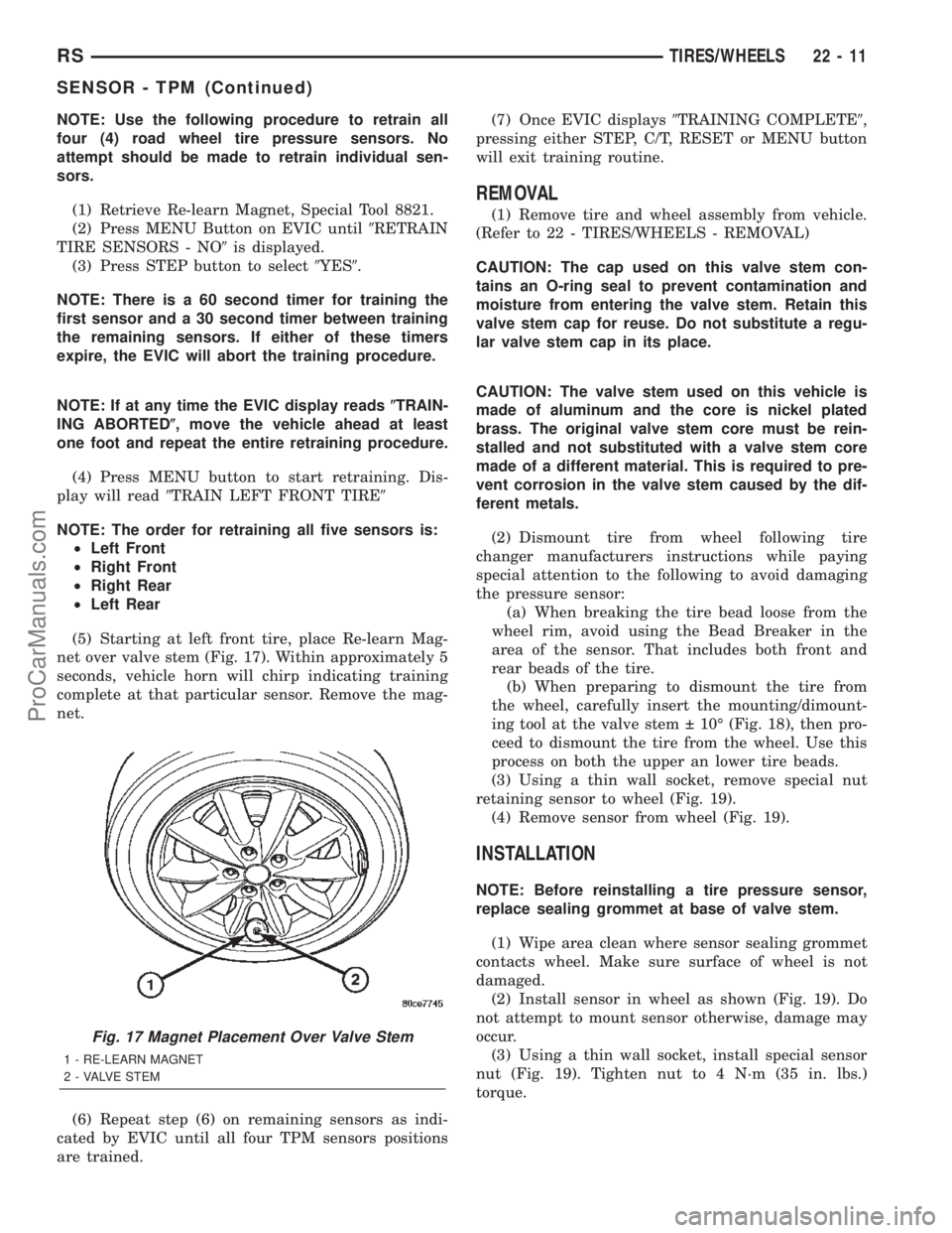
(5) Starting at left front tire, place Re-learn Mag-
net over valve stem (Fig. 17). Within approximately 5
seconds, vehicle horn will chirp indicating training
complete at that particular sensor. Remove the mag-
net.
(6) Repeat step (6) on remaining sensors as indi-
cated by EVIC until all four TPM sensors positions
are trained.(7) Once EVIC displays9TRAINING COMPLETE9,
pressing either STEP, C/T, RESET or MENU button
will exit training routine.
REMOVAL
(1) Remove tire and wheel assembly from vehicle.
(Refer to 22 - TIRES/WHEELS - REMOVAL)
CAUTION: The cap used on this valve stem con-
tains an O-ring seal to prevent contamination and
moisture from entering the valve stem. Retain this
valve stem cap for reuse. Do not substitute a regu-
lar valve stem cap in its place.
CAUTION: The valve stem used on this vehicle is
made of aluminum and the core is nickel plated
brass. The original valve stem core must be rein-
stalled and not substituted with a valve stem core
made of a different material. This is required to pre-
vent corrosion in the valve stem caused by the dif-
ferent metals.
(2) Dismount tire from wheel following tire
changer manufacturers instructions while paying
special attention to the following to avoid damaging
the pressure sensor:
(a) When breaking the tire bead loose from the
wheel rim, avoid using the Bead Breaker in the
area of the sensor. That includes both front and
rear beads of the tire.
(b) When preparing to dismount the tire from
the wheel, carefully insert the mounting/dimount-
ing tool at the valve stem 10É (Fig. 18), then pro-
ceed to dismount the tire from the wheel. Use this
process on both the upper an lower tire beads.
(3) Using a thin wall socket, remove special nut
retaining sensor to wheel (Fig. 19).
(4) Remove sensor from wheel (Fig. 19).
INSTALLATION
NOTE: Before reinstalling a tire pressure sensor,
replace sealing grommet at base of valve stem.
(1) Wipe area clean where sensor sealing grommet
contacts wheel. Make sure surface of wheel is not
damaged.
(2) Install sensor in wheel as shown (Fig. 19). Do
not attempt to mount sensor otherwise, damage may
occur.
(3) Using a thin wall socket, install special sensor
nut (Fig. 19). Tighten nut to 4 N´m (35 in. lbs.)
torque.
Fig. 17 Magnet Placement Over Valve Stem
1 - RE-LEARN MAGNET
2 - VALVE STEM
RSTIRES/WHEELS22-11
SENSOR - TPM (Continued)
ProCarManuals.com
Page 2273 of 2399

bezel with the snap clip receptacles on the retainer
above the headliner.
(7) Using hand pressure, press the top edge of the
rear heater-A/C control bezel upward until the two
snap clips are fully seated in their receptacles.
(8) Reconnect the battery negative cable.
(9) Using the DRB-IIItreset the Rear Tempera-
ture Selector calibration values.
(10) Verify that the Actuator Calibration of the
Front Control has passed. If an Actuator Calibration
has not passed correct any errors before proceeding
further.
(11) Rotate the Rear Temperature Selector counter
clockwise to the Cold Position, allow the Selector to
remain in the Cold Position for 5 seconds.
(12) Rotate the Rear Temperature Selector Clock-
wise to the Hot Position, allow the Selector to remain
in the Cold Position for 5 seconds.
(13) calibration is now complete.
BLEND DOOR ACTUATOR
DESCRIPTION
The blend door actuator is a reversible, 12-volt
Direct Current (DC), servo motor (Fig. 3). The single
blend door actuator is located on the outboard side of
the rear heater-A/C unit housing, below the mode
door actuator. The blend door actuator is mechani-
cally connected to the blend air door. The blend door
actuator is interchangeable with the actuator for the
mode door. Each actuator is contained within an
identical black molded plastic housing with an inte-gral wire connector receptacle. Two integral mount-
ing tabs allow the actuator to be secured with two
screws to the rear heater-A/C unit housing. Each
actuator also has an identical output shaft with
splines that connects it to the pivot or linkage of the
proper door. The blend door actuator does not require
mechanical indexing to the blend air door pivot, as it
is electronically calibrated by the front heater-A/C
control module. The blend door actuator cannot be
adjusted or repaired and, if damaged or faulty, it
must be replaced.
OPERATION
The blend door actuator is connected to the front
heater-A/C control module through the vehicle elec-
trical system by a dedicated two-wire take out and
connector of the rear HVAC wire harness. The blend
door actuator can move the blend air door in two
directions. When the front heater-A/C control module
pulls the voltage on one side of the motor connection
Fig. 2 Heater-A/C Control Bezel
1 - BEZEL
2 - SNAP CLIP (2)
3 - HEATER-A/C CONTROL
4 - SCREW (3)
5 - LOCATOR TAB (2)
Fig. 3 Blend Door Actuator
1 - SCREW (2)
2 - MODE DOOR ACTUATOR
3 - SCREW (2)
4 - CONNECTOR
5 - BLEND DOOR ACTUATOR
6 - CONNECTOR
24 - 30 CONTROLS - REARRS
A/C-HEATER CONTROL (Continued)
ProCarManuals.com