diagram CHRYSLER CARAVAN 2003 Owners Manual
[x] Cancel search | Manufacturer: CHRYSLER, Model Year: 2003, Model line: CARAVAN, Model: CHRYSLER CARAVAN 2003Pages: 2177, PDF Size: 59.81 MB
Page 1616 of 2177
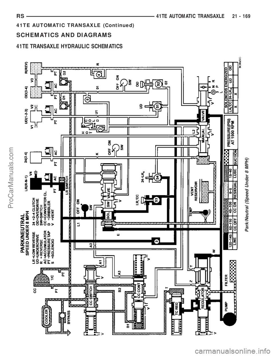
SCHEMATICS AND DIAGRAMS
41TE TRANSAXLE HYDRAULIC SCHEMATICS
Park/Neutral (Speed Under 8 MPH)
RS41TE AUTOMATIC TRANSAXLE21 - 169
41TE AUTOMATIC TRANSAXLE (Continued)
ProCarManuals.com
Page 1846 of 2177
SUNROOF
TABLE OF CONTENTS
page page
SUNROOF
DESCRIPTION........................113
DIAGNOSIS AND TESTING - SUNROOF.....113
DRAIN TUBE
REMOVAL............................116
INSTALLATION........................117
GLASS PANEL
REMOVAL............................117
INSTALLATION........................117
ADJUSTMENTS
SUNROOF GLASS PANEL ADJUSTMENT . . 117
SUNROOF ASSEMBLY
REMOVAL............................117
INSTALLATION........................117
SUNSHADE
REMOVAL............................117INSTALLATION........................118
WIND DEFLECTOR
REMOVAL............................118
INSTALLATION........................118
WATER CHANNEL
REMOVAL............................118
INSTALLATION........................118
SUNROOF MOTOR
REMOVAL............................118
INSTALLATION........................118
ADJUSTMENTS
ADJUSTMENT.......................119
SUNROOF SWITCH
REMOVAL............................120
INSTALLATION........................120
SUNROOF
DESCRIPTION
WARNING: Keep fingers and other body parts out
of sunroof opening at all times.
The sun roof features consists of: (Fig. 1)
²Sun roof glass
²Sun roof sun shade
The sunroof power sliding glass panel and sun-
shade can be positioned anywhere along its travel,
rearward of glass panel front edge.
The sunroof is electrically operated from a switch
located in the overhead console. To operate the sun-
roof the ignition switch must be in the Accessory or
On/Run position. Both switchs are a rocker style
design that open or close the sunroof. When pressing
and releasing the open button once, the sunroof will
express open to the comfort stop and the wind deflec-
tor will raise. If the button is pressed a second time,
the sunroof will continue to open to full travel unless
the button is released, at which time it will stop in
that position. Pressing and holding the close button
will close the sunroof. If the close button is released
before the glass fully closes, the sunroof will stop in
that position. The vent switch operates in a similar
manor. The sunroof will also operate for up to fifteen
minutes after the ignition key is turned off for cus-
tomer comfort and convenance while parking.
DIAGNOSIS AND TESTING - SUNROOF
Refer to Sunroof Diagnostic Chart for possible
causes. Before beginning sunroof diagnostics verify
that all other power accessories are in proper operat-
ing condition. If not, a common electrical problem
may exist. Refer to Wiring Diagrams, in this publica-
tion for circuit, splice and component descriptions.
Check the condition of the circuit protection (20 amp
circuit breaker in the Junction Block). Inspect all
wiring connector pins for proper engagement and
continuity. Check for battery voltage at the power
sunroof controller, refer to Wiring Diagrams, for cir-
cuit information. If battery voltage of more than 10
volts is detected at the controller, proceed with the
following tests (the controller will not operate at less
than 10 volts).
Before beginning diagnosis for wind noise or water
leaks, verify that the problem was not caused by
releasing the control switch before the sunroof was
fully closed. The sunroof module has a water-man-
agement system. If however, the sunroof glass is in a
partial closed position, high pressure water may be
forced beyond the water management system bound-
aries and onto the headlining.
RSSUNROOF23 - 113
ProCarManuals.com
Page 2010 of 2177
conditioner housing. Tighten the screws to 2 N´m (17
in. lbs.).
(6) Reinstall the silencer under the driver side end
of the instrument panel. (Refer to 23 - BODY/IN-
STRUMENT PANEL/INSTRUMENT PANEL
SILENCER - INSTALLATION).
(7) Reconnect the battery negative cable.
(8) Perform the heater-A/C control calibration pro-
cedure. (Refer to 24 - HEATING & AIR CONDITION-
ING/CONTROLS - FRONT/A/C-HEATER CONTROL
- STANDARD PROCEDURE - HEATER-A/C CON-
TROL CALIBRATION).
BLOWER MOTOR RELAY
DESCRIPTION
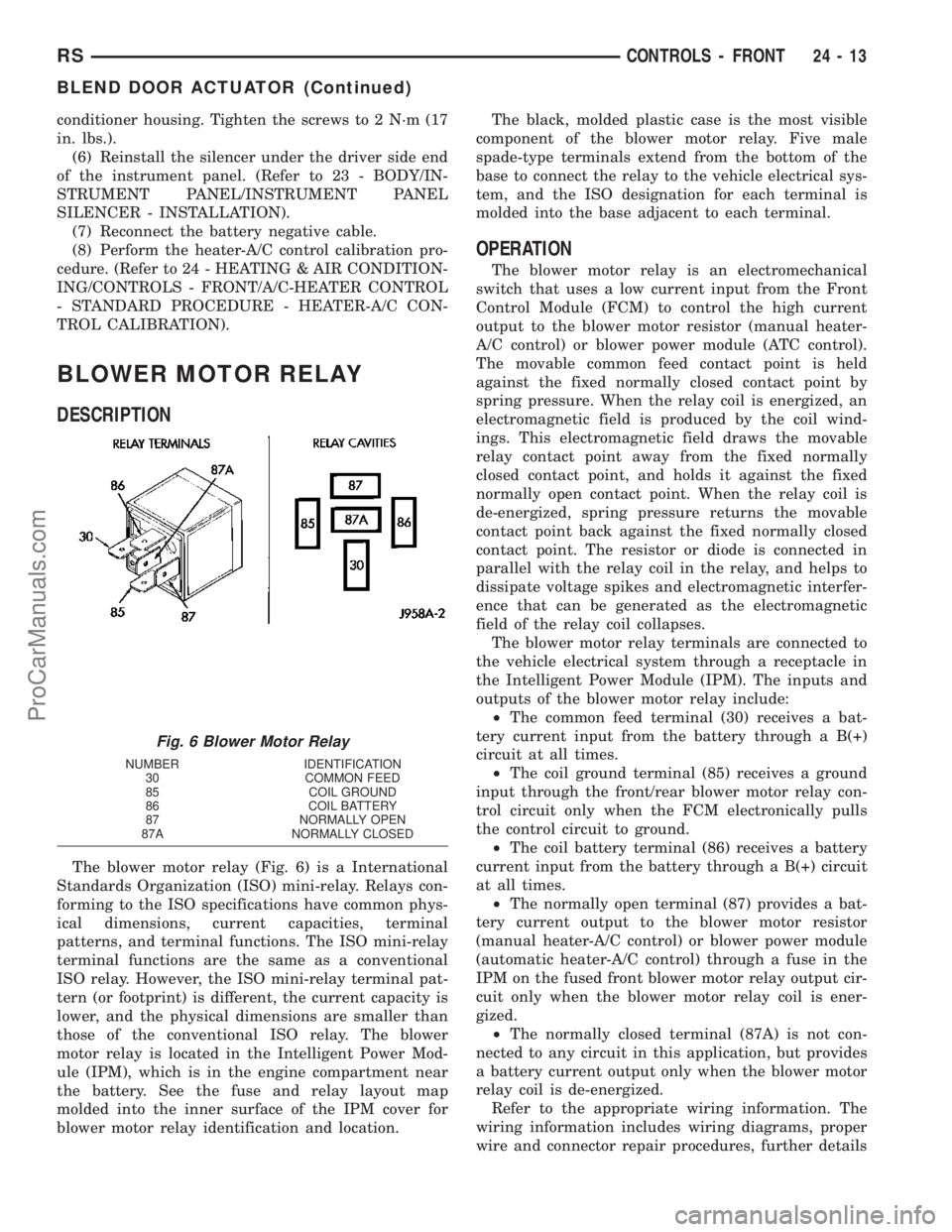
The blower motor relay (Fig. 6) is a International
Standards Organization (ISO) mini-relay. Relays con-
forming to the ISO specifications have common phys-
ical dimensions, current capacities, terminal
patterns, and terminal functions. The ISO mini-relay
terminal functions are the same as a conventional
ISO relay. However, the ISO mini-relay terminal pat-
tern (or footprint) is different, the current capacity is
lower, and the physical dimensions are smaller than
those of the conventional ISO relay. The blower
motor relay is located in the Intelligent Power Mod-
ule (IPM), which is in the engine compartment near
the battery. See the fuse and relay layout map
molded into the inner surface of the IPM cover for
blower motor relay identification and location.The black, molded plastic case is the most visible
component of the blower motor relay. Five male
spade-type terminals extend from the bottom of the
base to connect the relay to the vehicle electrical sys-
tem, and the ISO designation for each terminal is
molded into the base adjacent to each terminal.
OPERATION
The blower motor relay is an electromechanical
switch that uses a low current input from the Front
Control Module (FCM) to control the high current
output to the blower motor resistor (manual heater-
A/C control) or blower power module (ATC control).
The movable common feed contact point is held
against the fixed normally closed contact point by
spring pressure. When the relay coil is energized, an
electromagnetic field is produced by the coil wind-
ings. This electromagnetic field draws the movable
relay contact point away from the fixed normally
closed contact point, and holds it against the fixed
normally open contact point. When the relay coil is
de-energized, spring pressure returns the movable
contact point back against the fixed normally closed
contact point. The resistor or diode is connected in
parallel with the relay coil in the relay, and helps to
dissipate voltage spikes and electromagnetic interfer-
ence that can be generated as the electromagnetic
field of the relay coil collapses.
The blower motor relay terminals are connected to
the vehicle electrical system through a receptacle in
the Intelligent Power Module (IPM). The inputs and
outputs of the blower motor relay include:
²The common feed terminal (30) receives a bat-
tery current input from the battery through a B(+)
circuit at all times.
²The coil ground terminal (85) receives a ground
input through the front/rear blower motor relay con-
trol circuit only when the FCM electronically pulls
the control circuit to ground.
²The coil battery terminal (86) receives a battery
current input from the battery through a B(+) circuit
at all times.
²The normally open terminal (87) provides a bat-
tery current output to the blower motor resistor
(manual heater-A/C control) or blower power module
(automatic heater-A/C control) through a fuse in the
IPM on the fused front blower motor relay output cir-
cuit only when the blower motor relay coil is ener-
gized.
²The normally closed terminal (87A) is not con-
nected to any circuit in this application, but provides
a battery current output only when the blower motor
relay coil is de-energized.
Refer to the appropriate wiring information. The
wiring information includes wiring diagrams, proper
wire and connector repair procedures, further details
Fig. 6 Blower Motor Relay
NUMBER IDENTIFICATION
30 COMMON FEED
85 COIL GROUND
86 COIL BATTERY
87 NORMALLY OPEN
87A NORMALLY CLOSED
RSCONTROLS - FRONT24-13
BLEND DOOR ACTUATOR (Continued)
ProCarManuals.com
Page 2012 of 2177
module, instead of the blower motor resistor. The
blower motor resistor is installed in a mounting hole
in the heater/AC housing, directly behind the glove
box opening of the instrument panel. The resistor
consists of a molded plastic mounting plate with two
integral connector receptacles. Concealed behind the
mounting plate within the heater/AC housing are
four coiled resistor wires contained within a protec-
tive stamped steel cage. The resistor mounting plate
is secured with two screws to the heater/AC housing
and is accessed for service by rolling down the glove
box from the instrument panel.
The blower motor resistor wires will get hot when
in use. Do not touch the resistor wires or the protec-
tive cage if the blower motor has been running. The
blower motor resistor cannot be adjusted or repaired
and, if faulty or damaged, it must be replaced.
OPERATION
The blower motor resistor is connected to the vehi-
cle electrical system through a dedicated take out
and connector of the instrument panel wire harness.
A second connector receptacle receives the pigtail
wire connector from the blower motor. The blower
motor resistor has multiple resistor wires, each of
which will reduce the current flow through the
blower motor to change the blower motor speed. The
blower motor switch in the manual heater-A/C con-
trol directs the ground path for the blower motor
through the correct resistor wire to obtain theselected speed. With the blower motor switch in the
lowest speed position, the ground path for the motor
is applied through all of the resistor wires. Each
higher speed selected with the blower motor switch
applies the blower motor ground path through fewer
of the resistor wires, increasing the blower motor
speed. When the blower motor switch is in the high-
est speed position, the blower motor resistor wires
are bypassed and the blower motor receives a direct
path to ground through the blower motor switch. The
blower motor resistor may be diagnosed using con-
ventional diagnostic tools and methods.
DIAGNOSIS AND TESTING - BLOWER MOTOR
RESISTOR
Refer to the appropriate wiring information. The
wiring information includes wiring diagrams, proper
wire and connector repair procedures, details of wire
harness routing and retention, connector pin-out
information and location views for the various wire
harness connectors, splices and grounds.
WARNING: ON VEHICLES EQUIPPED WITH AIR-
BAGS, DISABLE THE AIRBAG SYSTEM BEFORE
ATTEMPTING ANY STEERING WHEEL, STEERING
COLUMN, OR INSTRUMENT PANEL COMPONENT
DIAGNOSIS OR SERVICE. DISCONNECT AND ISO-
LATE THE BATTERY NEGATIVE (GROUND) CABLE,
THEN WAIT TWO MINUTES FOR THE AIRBAG SYS-
TEM CAPACITOR TO DISCHARGE BEFORE PER-
FORMING FURTHER DIAGNOSIS OR SERVICE. THIS
IS THE ONLY SURE WAY TO DISABLE THE AIRBAG
SYSTEM. FAILURE TO TAKE THE PROPER PRE-
CAUTIONS COULD RESULT IN ACCIDENTAL AIR-
BAG DEPLOYMENT AND POSSIBLE PERSONAL
INJURY.
(1) Disconnect and isolate the battery negative
cable.
(2) Disconnect the instrument panel wire harness
connector for the blower motor resistor and the
blower motor pigtail wire connector from the resistor
connector receptacles.
(3) Check for continuity between each of the
blower motor switch input terminals of the blower
motor resistor and the resistor output terminal. In
each case there should be continuity. If OK, repair
the instrument panel wire harness circuits between
the blower motor switch and the blower motor resis-
tor or the blower motor pigtail wires as required. If
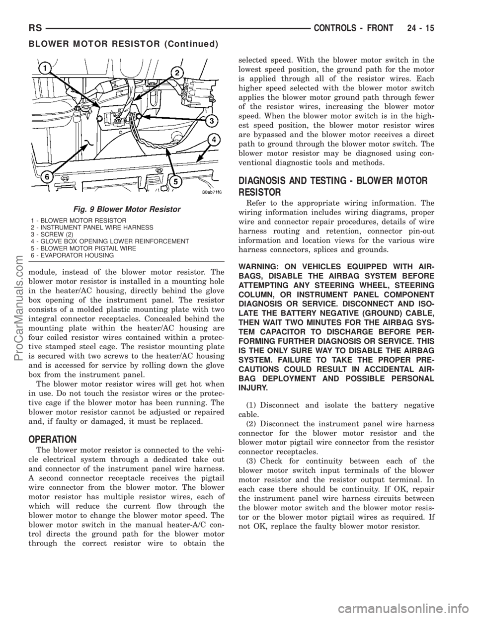
not OK, replace the faulty blower motor resistor.Fig. 9 Blower Motor Resistor
1 - BLOWER MOTOR RESISTOR
2 - INSTRUMENT PANEL WIRE HARNESS
3 - SCREW (2)
4 - GLOVE BOX OPENING LOWER REINFORCEMENT
5 - BLOWER MOTOR PIGTAIL WIRE
6 - EVAPORATOR HOUSING
RSCONTROLS - FRONT24-15
BLOWER MOTOR RESISTOR (Continued)
ProCarManuals.com
Page 2018 of 2177
DRBIIItscan tool to perform further diagnosis. Refer
to the appropriate diagnostic information.
TESTS
(1) Verify the battery state of charge. (Refer to 8 -
ELECTRICAL/BATTERY SYSTEM/BATTERY -
DIAGNOSIS AND TESTING).
(2) Connect an ammeter (0 to 10 ampere scale
selected) in series with the clutch coil feed terminal.
Connect a voltmeter (0 to 20 volt scale selected) to
measure voltage across the battery and the clutch
coil.
(3) With the heater-A/C control in the A/C mode
and the blower at low speed, start the engine and
allow it to run at a normal idle speed.
(4) The compressor clutch should engage immedi-
ately, and the clutch coil voltage should be within
two volts of the battery voltage. If the coil voltage is
not within two volts of battery voltage, test the
clutch coil feed circuit for excessive voltage drop. If
the compressor clutch does not engage, use a
DRBIIItscan tool to perform further diagnosis. Refer
to the appropriate diagnostic information.
(5) With the ambient temperature at 21É C (70É F),
the compressor clutch coil is acceptable if the current
draw is 2.0 to 3.7 amperes at 11.5 to 12.5 volts at the
clutch coil. If the voltage is more than 12.5 volts, add
electrical loads by turning on electrical accessories
until the voltage reads below 12.5 volts.
(a) If the compressor clutch coil current reading
is zero, the coil is open and must be replaced.
(b) If the compressor clutch coil current reading
is four amperes or more, the coil is shorted and
must be replaced.
COMPRESSOR CLUTCH RELAY
DESCRIPTION
The compressor clutch relay (Fig. 17) is a Interna-
tional Standards Organization (ISO) micro-relay.
Relays conforming to the ISO specifications have
common physical dimensions, current capacities, ter-
minal patterns, and terminal functions. The ISO
micro-relay terminal functions are the same as a con-
ventional ISO relay. However, the ISO micro-relay
terminal pattern (or footprint) is different, the cur-
rent capacity is lower, and the physical dimensions
are smaller than those of the conventional ISO relay.
The compressor clutch relay is located in the Intelli-
gent Power Module (IPM), which is in the engine
compartment near the battery. See the fuse and relay
layout map molded into the inner surface of the IPM
cover for compressor clutch relay identification and
location.The black, molded plastic case is the most visible
component of the compressor clutch relay. Five male
spade-type terminals extend from the bottom of the
base to connect the relay to the vehicle electrical sys-
tem, and the ISO designation for each terminal is
molded into the base adjacent to each terminal.
OPERATION
The compressor clutch relay is an electromechani-
cal switch that uses a low current input from the
Powertrain Control Module (PCM) to control the high
current output to the compressor clutch electromag-
netic coil. The movable common feed contact point is
held against the fixed normally closed contact point
by spring pressure. When the relay coil is energized,
an electromagnetic field is produced by the coil wind-
ings. This electromagnetic field draws the movable
relay contact point away from the fixed normally
closed contact point, and holds it against the fixed
normally open contact point. When the relay coil is
de-energized, spring pressure returns the movable
contact point back against the fixed normally closed
contact point. The resistor or diode is connected in
parallel with the relay coil in the relay, and helps to
dissipate voltage spikes and electromagnetic interfer-
ence that can be generated as the electromagnetic
field of the relay coil collapses.
The compressor clutch relay terminals are con-
nected to the vehicle electrical system through a
receptacle in the Intelligent Power Module (IPM).
The inputs and outputs of the compressor clutch
relay include:
²The common feed terminal (30) receives a bat-
tery current input from a fuse in the IPM through a
fused B(+) circuit at all times.
²The coil ground terminal (85) receives a ground
input from the PCM through the compressor clutch
relay control circuit only when the PCM electroni-
cally pulls the control circuit to ground.
²The coil battery terminal (86) receives a battery
current input from the PCM through a fused ignition
switch output (run-start) circuit only when the igni-
tion switch is in the On or Start positions.
²The normally open terminal (87) provides a bat-
tery current output to the compressor clutch coil
through the compressor clutch relay output circuit
only when the compressor clutch relay coil is ener-
gized.
²The normally closed terminal (87A) is not con-
nected to any circuit in this application, but provides
a battery current output only when the compressor
clutch relay coil is de-energized.
Refer to the appropriate wiring information. The
wiring information includes wiring diagrams, proper
wire and connector repair procedures, further details
on wire harness routing and retention, as well as
RSCONTROLS - FRONT24-21
COMPRESSOR CLUTCH COIL (Continued)
ProCarManuals.com
Page 2030 of 2177
trol circuit only when the FCM electronically pulls
the control circuit to ground.
²The coil battery terminal (86) receives a battery
current input from the battery through a B(+) circuit
at all times.
²The normally open terminal (87) provides a bat-
tery current output to the blower motor resistor
(manual heater-A/C control) or blower power module
(automatic heater-A/C control) through a fuse in the
IPM on the fused rear blower motor relay output cir-
cuit only when the blower motor relay coil is ener-
gized.
²The normally closed terminal (87A) is not con-
nected to any circuit in this application, but provides
a battery current output only when the blower motor
relay coil is de-energized.
Refer to the appropriate wiring information. The
wiring information includes wiring diagrams, proper
wire and connector repair procedures, further details
on wire harness routing and retention, as well as
pin-out and location views for the various wire har-
ness connectors, splices, and grounds.
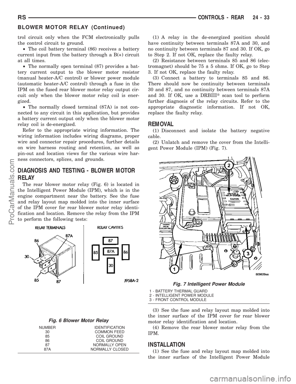
DIAGNOSIS AND TESTING - BLOWER MOTOR
RELAY
The rear blower motor relay (Fig. 6) is located in
the Intelligent Power Module (IPM), which is in the
engine compartment near the battery. See the fuse
and relay layout map molded into the inner surface
of the IPM cover for rear blower motor relay identi-
fication and location. Remove the relay from the IPM
to perform the following tests:(1) A relay in the de-energized position should
have continuity between terminals 87A and 30, and
no continuity between terminals 87 and 30. If OK, go
to Step 2. If not OK, replace the faulty relay.
(2) Resistance between terminals 85 and 86 (elec-
tromagnet) should be 75 5 ohms. If OK, go to Step
3. If not OK, replace the faulty relay.
(3) Connect a battery to terminals 85 and 86.
There should now be continuity between terminals
30 and 87, and no continuity between terminals 87A
and 30. If OK, use a DRBIIItscan tool to perform
further diagnosis of the relay circuits. Refer to the
appropriate diagnostic information. If not OK,
replace the faulty relay.
REMOVAL
(1) Disconnect and isolate the battery negative
cable.
(2) Unlatch and remove the cover from the Intelli-
gent Power Module (IPM) (Fig. 7).
(3) See the fuse and relay layout map molded into
the inner surface of the IPM cover for rear blower
motor relay identification and location.
(4) Remove the rear blower motor relay from the
IPM.
INSTALLATION
(1) See the fuse and relay layout map molded into
the inner surface of the Intelligent Power Module
Fig. 6 Blower Motor Relay
NUMBER IDENTIFICATION
30 COMMON FEED
85 COIL GROUND
86 COIL GROUND
87 NORMALLY OPEN
87A NORMALLY CLOSED
Fig. 7 Intelligent Power Module
1 - BATTERY THERMAL GUARD
2 - INTELLIGENT POWER MODULE
3 - FRONT CONTROL MODULE
RSCONTROLS - REAR24-33
BLOWER MOTOR RELAY (Continued)
ProCarManuals.com
Page 2031 of 2177
(IPM) cover for rear blower motor relay identification
and location.
(2) Position the rear blower motor relay to the
proper receptacle in the IPM.
(3) Align the rear blower motor relay terminals
with the terminal cavities in the IPM relay recepta-
cle.
(4) Push down firmly on the rear blower motor
relay until the terminals are fully seated in the ter-
minal cavities in the IPM receptacle.
(5) Install and latch the cover onto the IPM.
(6) Reconnect the battery negative cable.
BLOWER MOTOR RESISTOR
DESCRIPTION
A blower motor resistor is used on this model when
it is equipped with the manual heater-A/C control
(Fig. 8). Models equipped with the optional Auto-
matic Temperature Control (ATC) use a blower powermodule, instead of the blower motor resistor. The
blower motor resistor is installed in a mounting hole
on the back of the rear heater-A/C unit housing,
directly above the expansion valve. The resistor con-
sists of a molded plastic mounting plate with an inte-
gral connector receptacle. Concealed behind the
mounting plate within the rear heater-A/C unit hous-
ing is an electrical circuit board.. The resistor mount-
ing plate is secured with two screws to the rear
heater-A/C unit housing and is accessed for service
by removing the right quarter and D-pillar trim pan-
els.
The blower motor resistor cannot be adjusted or
repaired and, if faulty or damaged, it must be
replaced.
OPERATION
The blower motor resistor is connected to the vehi-
cle electrical system through a dedicated take out
and connector of the rear HVAC wire harness. The
blower motor resistor has an electrical circuit board
which will reduce the current flow through the
blower motor to change the blower motor speed. The
blower motor switch in the manual heater-A/C con-
trol directs the ground path for the blower motor
through the correct resistor wire to obtain the
selected speed. With the blower motor switch in the
lowest speed position, the ground path for the motor
is applied through both resistor wires. Each higher
speed selected with the blower motor switch applies
the blower motor ground path through fewer of the
resistor wires, increasing the blower motor speed.
When the blower motor switch is in the highest
speed position, the blower motor resistor wires are
bypassed and the blower motor receives a direct path
to ground through the blower motor switch. The
blower motor resistor may be diagnosed using con-
ventional diagnostic tools and methods.
DIAGNOSIS AND TESTING - BLOWER MOTOR
RESISTOR
Refer to the appropriate wiring information. The
wiring information includes wiring diagrams, proper
wire and connector repair procedures, details of wire
harness routing and retention, connector pin-out
information and location views for the various wire
harness connectors, splices and grounds.
(1) Disconnect and isolate the battery negative
cable.
(2) Disconnect the rear HVAC wire harness con-
nector for the blower motor resistor from the resistor
connector receptacle.
(3) Check for continuity between each of the
blower motor switch input terminals of the blower
motor resistor and the resistor output terminal. In
each case there should be continuity. If OK, repair
Fig. 8 Blower Motor Resistor
1 - REAR HEATER-A/C UNIT HOUSING
2 - D-PILLAR
3 - BLOWER PIGTAIL WIRE
4 - CONNECTOR
5 - EXPANSION VALVE
6 - SCREW (2)
7 - BLOWER MOTOR RESISTOR
24 - 34 CONTROLS - REARRS
BLOWER MOTOR RELAY (Continued)
ProCarManuals.com
Page 2148 of 2177
CUSHION SIDE COVER - INSTALLATION,
FRONT SEAT........................23-93
CUSHION SIDE COVER - REMOVAL,
FRONT SEAT........................23-93
CV BOOT - INNER - INSTALLATION........3-6
CV BOOT - INNER - REMOVAL............3-6
CV BOOT - INNER/OUTER -
INSTALLATION........................3-17
CV BOOT - INNER/OUTER - REMOVAL.....3-15
CV BOOT - OUTER - INSTALLATION.......3-10
CV BOOT - OUTER - REMOVAL...........3-10
CYCLE - STANDARD PROCEDURE,
POWER DOOR LEARN................8N-28
CYCLE - STANDARD PROCEDURE,
POWER LIFTGATE LEARN...............8N-9
CYLINDER - DESCRIPTION, KEY/LOCK....19-20
CYLINDER - DESCRIPTION, STANDARD 4 . . . 8I-9
CYLINDER - INSTALLATION, KEY/LOCK . . . 19-20
CYLINDER - INSTALLATION, LOCK . . 23-20,23-41
CYLINDER - INSTALLATION, SLAVE.......6-11
CYLINDER - INSTALLATION, SUPPORT....23-42
CYLINDER - LHD - INSTALLATION,
MASTER............................6-10
CYLINDER - LHD - REMOVAL, MASTER.....6-9
CYLINDER - OPERATION, KEY/LOCK......19-20
CYLINDER - REMOVAL, KEY/LOCK.......19-20
CYLINDER - REMOVAL, LOCK......23-19,23-41
CYLINDER - REMOVAL, SLAVE...........6-11
CYLINDER - REMOVAL, SUPPORT.......23-42
CYLINDER - RHD - INSTALLATION,
MASTER.............................6-9
CYLINDER - RHD - REMOVAL, MASTER.....6-8
CYLINDER BLEEDING - STANDARD
PROCEDURE, MASTER.................5-35
CYLINDER BORE FITTING - STANDARD
PROCEDURE, PISTON TO...............9-42
CYLINDER BORE HONING - STANDARD
PROCEDURE....................9-112,9-35
CYLINDER COMBUSTION PRESSURE
LEAKAGE TEST - DIAGNOSIS AND
TESTING.........................9-83,9-9
CYLINDER COMPRESSION PRESSURE
TEST - DIAGNOSIS AND TESTING.....9-83,9-9
CYLINDER (FLUID RESERVOIR) -
ASSEMBLY, MASTER...................5-38
CYLINDER (FLUID RESERVOIR) -
DISASSEMBLY, MASTER................5-37
CYLINDER HEAD - CLEANING.......9-100,9-26
CYLINDER HEAD - DESCRIPTION.....9-24,9-99
CYLINDER HEAD - INSPECTION.....9-101,9-26
CYLINDER HEAD - INSTALLATION . . . 9-101,9-26
CYLINDER HEAD - REMOVAL.......9-100,9-25
CYLINDER HEAD COVER - CLEANING......9-31
CYLINDER HEAD COVER - INSPECTION....9-31
CYLINDER HEAD COVER -
INSTALLATION........................9-31
CYLINDER HEAD COVER - LEFT -
INSTALLATION.......................9-103
CYLINDER HEAD COVER - LEFT -
REMOVAL..........................9-103
CYLINDER HEAD COVER - REMOVAL......9-31
CYLINDER HEAD COVER - RIGHT -
INSTALLATION.......................9-103
CYLINDER HEAD COVER - RIGHT -
REMOVAL..........................9-102
CYLINDER HEAD COVER(S) -
DESCRIPTION.......................9-102
CYLINDER HEAD GASKET - DIAGNOSIS
AND TESTING....................9-24,9-99
CYLINDER HEAD OFF - INSTALLATION . . . 9-108,
9-33
CYLINDER HEAD OFF - REMOVAL . . . 9-106,9-32
CYLINDER HEAD ON - INSTALLATION....9-108,
9-33
CYLINDER HEAD ON - REMOVAL....9-106,9-32
CYLINDER HOUSING - INSTALLATION,
LOCK..............................19-19
CYLINDER HOUSING - REMOVAL, LOCK . . 19-17
CYLINDER LOCK SWITCH -
DESCRIPTION, DOOR
.................8N-40
CYLINDER LOCK SWITCH - DIAGNOSIS
AND TESTING, DOOR
.................8N-40
CYLINDER LOCK SWITCH -
INSTALLATION, DOOR
.................8N-41
CYLINDER LOCK SWITCH - OPERATION,
DOOR
.............................8N-40
CYLINDER LOCK SWITCH - REMOVAL,
DOOR
.............................8N-41CYLINDERS - INSPECTION, WHEEL.......5-57
CYLINDERS - INSTALLATION, WHEEL.....5-57
CYLINDERS - REMOVAL, WHEEL.........5-57
DAMAGED OR WORN THREADS -
STANDARD PROCEDURE, REPAIR OF . . 9-10,9-86
DAMPER - INSTALLATION, VIBRATION . . . 9-130,
9-47
DAMPER - REMOVAL, VIBRATION . . . 9-130,9-47
DATA BUS COMMUNICATION RECEIVE -
PCM INPUT - OPERATION..............8E-15
DATA LINK CONNECTOR - DESCRIPTION . . . 8E-6
DATA LINK CONNECTOR - OPERATION.....8E-7
DAY / NIGHT MIRROR - DESCRIPTION,
AUTOMATIC........................8N-47
DAY / NIGHT MIRROR - DIAGNOSIS AND
TESTING, AUTOMATIC................8N-47
DAY / NIGHT MIRROR - OPERATION,
AUTOMATIC........................8N-47
DCHA - DIAGNOSIS AND TESTING,
DIESEL SUPPLEMENTAL HEATER.......24-107
DCHA - EXPORT - DESCRIPTION, DIESEL
SUPPLEMENTAL HEATER.............24-106
DEAERATION - DIAGNOSIS AND
TESTING, COOLING SYSTEM.............7-4
DECOUPLER PULLEY - DESCRIPTION,
GENERATOR........................8F-25
DECOUPLER PULLEY - DIAGNOSIS AND
TESTING, GENERATOR................8F-25
DECOUPLER PULLEY - INSTALLATION,
GENERATOR........................8F-26
DECOUPLER PULLEY - OPERATION,
GENERATOR..........................8F-25
DECOUPLER PULLEY - REMOVAL,
GENERATOR........................8F-26
DEFINITION - DESCRIPTION, TRIP........25-1
DEFLECTOR - INSTALLATION, WIND.....23-118
DEFLECTOR - REMOVAL, WIND........23-118
DEFOGGER RELAY - DESCRIPTION.......8G-2
DEFOGGER SWITCH - DESCRIPTION,
REAR WINDOW.......................8G-2
DEFOGGER SWITCH - OPERATION, REAR
WINDOW............................8G-2
DEFROSTER DUCT - INSTALLATION......24-48
DEFROSTER DUCT - REMOVAL..........24-47
DEMAGNETIZING - STANDARD
PROCEDURE, COMPASS...............8M-4
DEMISTER DUCTS - INSTALLATION......24-48
DEMISTER DUCTS - REMOVAL..........24-48
DEMISTER OUTLET - INSTALLATION.....24-42
DEMISTER OUTLET - REMOVAL.........24-41
DEPLOYMENT - STANDARD
PROCEDURE, SERVICE AFTER AN
AIRBAG.............................8O-3
DETECTION ASSY - INSTALLATION,
NATURAL VAC LEAK..................25-13
DETECTION ASSY - REMOVAL, NATURAL
VAC LEAK..........................25-13
DETECTION PUMP - INSTALLATION,
LEAK..............................25-13
DETECTION PUMP - REMOVAL, LEAK....25-13
DEVICES - STANDARD PROCEDURE,
ELECTROSTATIC DISCHARGE (ESD)
SENSITIVE........................8W-01-8
DIAGNOSTIC SYSTEM - DIAGNOSIS AND
TESTING, ON-BOARD.................8F-21
DIAGNOSTIC TROUBLE CODES -
STANDARD PROCEDURE, OBTAINING.....8E-15
DIAGRAMS - 41TE TRANSAXLE
HYDRAULIC SCHEMATICS,
SCHEMATICS.......................21-169
DIAGRAMS - DESCRIPTION, HOW TO
USE WIRING......................8W-01-1
DIESEL - DESCRIPTION, 2.5L...........19-51
DIESEL - INSTALLATION, 2.5L..........19-52
DIESEL - REMOVAL, 2.5L..............19-51
DIESEL ENGINE - DESCRIPTION, FUEL
REQUIREMENTS.......................0-6
DIESEL ENGINES - DESCRIPTION,
ENGINE OIL...........................0-6
DIESEL HEATER WIRING -
INSTALLATION, SUPPLEMENTAL
........24-112
DIESEL HEATER WIRING - REMOVAL,
SUPPLEMENTAL
....................24-112
DIESEL SUPPLEMENTAL HEATER - DCHA
- DIAGNOSIS AND TESTING
...........24-107
DIESEL SUPPLEMENTAL HEATER - DCHA
- EXPORT - DESCRIPTION
............24-106
DIFFERENTIAL - ASSEMBLY
............21-66DIFFERENTIAL - DESCRIPTION..........21-62
DIFFERENTIAL - DISASSEMBLY.........21-62
DIFFERENTIAL - OPERATION............21-62
DIFFERENTIAL ASSEMBLY -
DESCRIPTION........................3-39
DIFFERENTIAL ASSEMBLY - OPERATION . . . 3-39
DIFFERENTIAL ASSEMBLY FLUID
CHANGE - STANDARD PROCEDURE.......3-40
DIFFERENTIAL BEARING PRELOAD -
ADJUSTMENT......................21-199
DIFFERENTIAL CARRIER SEAL -
INSTALLATION........................21-9
DIFFERENTIAL CARRIER SEAL -
REMOVAL...........................21-9
DIFFERENTIAL SIDE GEAR END PLAY -
ADJUSTMENT.......................21-70
DIFFERENTIAL TURNING TORQUE -
ADJUSTMENT.......................21-69
DIMENSIONS - SPECIFICATIONS, BODY
OPENING..........................23-124
DIMENSIONS, SPECIFICATIONS - FRAME . . . 13-4
DIODE - INSTALLATION............8W-01-14
DIODE - REMOVAL................8W-01-14
DISC AND PRESSURE PLATE - 2.5L TD -
INSTALLATION, CLUTCH................6-12
DISC AND PRESSURE PLATE - 2.5L TD -
REMOVAL, CLUTCH....................6-11
DISC BRAKE CALIPER - INSTALLATION,
REAR...............................5-30
DISC BRAKE CALIPER - REMOVAL,
REAR...............................5-27
DISC BRAKE CALIPER ADAPTER -
INSTALLATION, FRONT.................5-31
DISC BRAKE CALIPER ADAPTER -
REMOVAL, FRONT.....................5-31
DISC BRAKE CALIPER (DISC/DISC
BRAKES) - INSTALLATION, FRONT........5-27
DISC BRAKE CALIPER (DISC/DISC
BRAKES) - REMOVAL, FRONT............5-24
DISC BRAKE CALIPER (DISC/DRUM
BRAKES) - INSTALLATION, FRONT........5-27
DISC BRAKE CALIPER (DISC/DRUM
BRAKES) - REMOVAL, FRONT............5-24
DISC BRAKE CALIPER GUIDE PINS
(DISC/DRUM BRAKES) -
INSTALLATION........................5-31
DISC BRAKE CALIPER GUIDE PINS
(DISC/DRUM BRAKES) - REMOVAL.......5-31
DISC BRAKE SHOES - CLEANING.....5-16,5-18
DISC BRAKE SHOES - INSPECTION . . . 5-16,5-18
DISC BRAKE SHOES - INSTALLATION,
REAR...............................5-19
DISC BRAKE SHOES - REMOVAL, REAR....5-17
DISC BRAKE SHOES (DISC/DISC
BRAKES) - INSTALLATION, FRONT........5-16
DISC BRAKE SHOES (DISC/DISC
BRAKES) - REMOVAL, FRONT............5-14
DISC BRAKE SHOES (DISC/DRUM
BRAKES) - INSTALLATION, FRONT........5-17
DISC BRAKE SHOES (DISC/DRUM
BRAKES) - REMOVAL, FRONT............5-15
DISC BRAKES (EXPORT) - DESCRIPTION . . . 5-13
DISC BRAKES (FRONT) - DESCRIPTION....5-11
DISC BRAKES (FRONT) - OPERATION......5-13
DISC BRAKES (REAR) - DESCRIPTION.....5-12
DISC BRAKES (REAR) - OPERATION......5-13
DISC RUNOUT - DIAGNOSIS AND
TESTING, CLUTCH COVER...............6-6
DISCHARGE (ESD) SENSITIVE DEVICES -
STANDARD PROCEDURE,
ELECTROSTATIC...................8W-01-8
DISCHARGE LINE - INSTALLATION.......24-69
DISCHARGE LINE - REMOVAL..........24-68
DISPLAY TEST MODE, OPERATION - DRB
IIITSTATE ...........................25-9
DISTRIBUTION DUCT - INSTALLATION,
A/C................................24-53
DISTRIBUTION DUCT - INSTALLATION,
REAR HEATER.......................24-59
DISTRIBUTION DUCT - REMOVAL, A/C
....24-53
DISTRIBUTION DUCT - REMOVAL, REAR
HEATER
............................24-59
DISTRIBUTION DUCTS - INSTALLATION,
FLOOR
.............................24-49
DISTRIBUTION DUCTS - REMOVAL,
FLOOR
.............................24-48
DISTRIBUTION SYSTEM - DESCRIPTION,
POWER
..........................8W-97-1
RSINDEX9
Description Group-Page Description Group-Page Description Group-Page
ProCarManuals.com
Page 2155 of 2177
HINGE - INSTALLATION, LOWER........23-28
HINGE - INSTALLATION, UPPER.........23-35
HINGE - REMOVAL.........23-18,23-39,23-59
HINGE - REMOVAL, BENCH SEAT BACK . . 23-100
HINGE - REMOVAL, CENTER............23-24
HINGE - REMOVAL, LOWER............23-28
HINGE - REMOVAL, UPPER.............23-35
HINGE COVERS - QUAD BUCKET, 50/50
SPLIT, BENCH - INSTALLATION, SEAT
BACK.............................23-100
HINGE COVERS - QUAD BUCKET, 50/50
SPLIT, BENCH - REMOVAL, SEAT BACK . . 23-100
HOISTING - STANDARD PROCEDURE......0-15
HOLD OPEN LATCH - INSTALLATION.....23-25
HOLD OPEN LATCH - REMOVAL.........23-25
HOLD OPEN LATCH CABLE -
INSTALLATION.......................23-38
HOLD OPEN LATCH CABLE - REMOVAL . . . 23-37
HOLD OPEN LATCH STRIKER -
INSTALLATION.......................23-26
HOLD OPEN LATCH STRIKER -
REMOVAL..........................23-26
HOLDDOWN - DESCRIPTION, BATTERY . . . 8F-15
HOLDDOWN - INSTALLATION, BATTERY . . . 8F-16
HOLDDOWN - OPERATION, BATTERY.....8F-15
HOLDDOWN - REMOVAL, BATTERY......8F-16
HOLDER - INSTALLATION, CUP.........23-63
HOLDER - INSTALLATION, QUAD
BUCKET SEAT SIDE SHIELD - NO CUP.....23-96
HOLDER - INSTALLATION, QUAD
BUCKET SEAT SIDE SHIELD/CUP........23-95
HOLDER - REMOVAL, CUP.............23-63
HOLDER - REMOVAL, QUAD BUCKET
SEAT SIDE SHIELD - NO CUP...........23-96
HOLDER - REMOVAL, QUAD BUCKET
SEAT SIDE SHIELD/CUP...............23-95
HOLDING CLUTCHES - DESCRIPTION....21-207
HOLDING CLUTCHES - OPERATION.....21-207
HOLE REPAIR - DESCRIPTION,
THREADED........................Intro.-5
HONING - STANDARD PROCEDURE,
CYLINDER BORE.................9-112,9-35
HOOD - INSTALLATION................23-60
HOOD - REMOVAL....................23-59
HOOD AJAR SWITCH - EXPORT -
INSTALLATION.......................8Q-3
HOOD AJAR SWITCH - EXPORT -
REMOVAL...........................8Q-3
HORN - DIAGNOSIS AND TESTING.......8H-3
HORN - INSTALLATION.................8H-5
HORN - REMOVAL....................8H-5
HORN CHIRP PREFERENCE - STANDARD
PROCEDURE........................8N-42
HORN RELAY - DIAGNOSIS AND
TESTING............................8H-5
HORN RELAY - INSTALLATION...........8H-5
HORN RELAY - REMOVAL..............8H-5
HORN SWITCH - DESCRIPTION..........8H-5
HORN SYSTEM - DESCRIPTION..........8H-1
HORN SYSTEM - DIAGNOSIS AND
TESTING............................8H-1
HORN SYSTEM - OPERATION............8H-1
HOSE - EXPORT - INSTALLATION,
HEADLAMP WASHER.................8R-12
HOSE - EXPORT - REMOVAL, HEADLAMP
WASHER...........................8R-12
HOSE - INSTALLATION, HEATER . . . 24-101,24-80
HOSE - REMOVAL, HEATER......24-100,24-78
HOSE CLAMPS - DESCRIPTION...........7-1
HOSE CLAMPS - OPERATION.............7-2
HOSES - DESCRIPTION, BRAKE TUBES
....5-14
HOSES - INSPECTION, BRAKE TUBES
.....5-14
HOSES - INSTALLATION, WASHER
.......8R-16
HOSES - OPERATION, BRAKE TUBES
......5-14
HOSES - REMOVAL, WASHER
..........8R-16
HOSES AND CLAMP - STANDARD
PROCEDURE
.........................14-6
HOUSING - INSTALLATION, AIR
CLEANER
........................9-24,9-99
HOUSING - INSTALLATION, HVAC
........24-50
HOUSING - INSTALLATION, LOCK
CYLINDER
..........................19-19
HOUSING - INSTALLATION, REAR
HEATER-A/C
.........................24-58
HOUSING - REMOVAL, AIR CLEANER
. . 9-24,9-99
HOUSING - REMOVAL, HVAC
...........24-49
HOUSING - REMOVAL, LOCK CYLINDER
. . 19-17HOUSING - REMOVAL, REAR HEATER-A/
C .................................24-56
HOUSING FLUID CHANGE - STANDARD
PROCEDURE, OVERRUNNING CLUTCH.....3-41
HOUSING FLUID LEAKAGE - DIAGNOSIS
AND TESTING, TORQUE CONVERTER....21-123
HOW TO USE WIRING DIAGRAMS -
DESCRIPTION.....................8W-01-1
HUB / BEARING - DESCRIPTION.......2-30,2-5
HUB / BEARING - INSTALLATION......2-32,2-5
HUB / BEARING - OPERATION........2-30,2-5
HUB / BEARING - REMOVAL..........2-31,2-5
HUB AND BEARING - DIAGNOSIS AND
TESTING.........................2-30,2-5
HVAC - LWB - INSTALLATION, SEAT
BELT & RETRACTOR - SECOND ROW -
RIGHT OUTBOARD WITH REAR.........8O-15
HVAC - LWB - REMOVAL, SEAT BELT &
RETRACTOR - SECOND ROW - RIGHT
OUTBOARD WITH REAR...............8O-15
HVAC HOUSING - INSTALLATION........24-50
HVAC HOUSING - REMOVAL............24-49
HVAC LOUVER - INSTALLATION, REAR . . . 23-79
HVAC LOUVER - REMOVAL, REAR.......23-79
HYDRAULIC CIRCUITS AND VALVES -
OPERATION..........................5-83
HYDRAULIC LASH ADJUSTER NOISE
DIAGNOSIS - DIAGNOSIS AND
TESTING............................9-34
HYDRAULIC LASH ADJUSTERS -
INSTALLATION........................9-34
HYDRAULIC LASH ADJUSTERS -
REMOVAL...........................9-34
HYDRAULIC LIFTERS - DIAGNOSIS AND
TESTING...........................9-113
HYDRAULIC LIFTERS (CAM IN BLOCK) -
DESCRIPTION.......................9-113
HYDRAULIC LIFTERS (CAM IN BLOCK) -
INSTALLATION.......................9-114
HYDRAULIC LIFTERS (CAM IN BLOCK) -
REMOVAL..........................9-114
HYDRAULIC PRESSURE TESTS -
DIAGNOSIS AND TESTING............21-120
HYDRAULIC SCHEMATICS, SCHEMATICS
AND DIAGRAMS - 41TE TRANSAXLE....21-169
HYDROSTATIC LOCKED ENGINE -
STANDARD PROCEDURE............9-10,9-85
ICU - ASSEMBLY......................5-94
ICU - DISASSEMBLY...................5-93
ICU (INTEGRATED CONTROL UNIT) -
DESCRIPTION........................5-89
ICU (INTEGRATED CONTROL UNIT) -
OPERATION..........................5-90
IDENTIFICATION - DESCRIPTION,
FASTENER.........................Intro.-2
IDENTIFICATION - DESCRIPTION,
VEHICLE............................23-1
IDENTIFICATION AND INFORMATION -
DESCRIPTION, SECTION.............8W-01-6
IDENTIFICATION, DIAGNOSIS AND
TESTING - SEAL......................21-3
IDENTIFICATION NUMBER -
DESCRIPTION, VEHICLE..............Intro.-9
IDLE AIR CONTROL MOTOR -
DESCRIPTION.......................14-28
IDLE AIR CONTROL MOTOR -
INSTALLATION.......................14-29
IDLE AIR CONTROL MOTOR -
OPERATION.........................14-28
IDLE AIR CONTROL MOTOR - REMOVAL
. . 14-29
IGNITION COIL - DESCRIPTION
...........8I-6
IGNITION COIL - OPERATION
.............8I-6
IGNITION INTERLOCK - DESCRIPTION
....19-17
IGNITION SENSE - PCM INPUT -
OPERATION
.........................8E-15
IGNITION SWITCH - INSTALLATION
......19-16
IGNITION SWITCH - REMOVAL
..........19-14
IGNITION SYSTEM - DESCRIPTION
........8I-1
IGNITION SYSTEM - OPERATION
..........8I-1
IGNITION-OFF DRAW TEST - STANDARD
PROCEDURE
........................8F-13
IIITSTATE DISPLAY TEST MODE,
OPERATION - DRB
....................25-9
ILLUMINATION LAMPS - INSTALLATION,
CLUSTER
...........................8L-26
ILLUMINATION LAMPS - REMOVAL,
CLUSTER
...........................8L-26IMMOBILIZER MODULE - DESCRIPTION,
SENTRY KEY........................8E-18
IMMOBILIZER MODULE - INSTALLATION,
SENTRY KEY........................8E-19
IMMOBILIZER MODULE - OPERATION,
SENTRY KEY........................8E-18
IMMOBILIZER MODULE - REMOVAL,
SENTRY KEY........................8E-18
IMMOBILIZER SYSTEM - DIAGNOSIS
AND TESTING, SENTRY KEY.............8Q-3
IMPACT AIRBAG CONTROL MODULE -
DESCRIPTION, SIDE..................8O-17
IMPACT AIRBAG CONTROL MODULE -
INSTALLATION, SIDE.................8O-17
IMPACT AIRBAG CONTROL MODULE -
OPERATION, SIDE....................8O-17
IMPACT AIRBAG CONTROL MODULE -
REMOVAL, SIDE.....................8O-17
INBOARD - 50/50 BENCH -
INSTALLATION, SEAT BELT BUCKLE -
SECOND ROW.......................8O-12
INBOARD - 50/50 BENCH - REMOVAL,
SEAT BELT BUCKLE - SECOND ROW.....8O-12
INBOARD - INSTALLATION, SEAT BELT
BUCKLE - FRONT....................8O-11
INBOARD - QUAD BUCKET -
INSTALLATION, SEAT BELT BUCKLE -
FIRST ROW.........................8O-11
INBOARD - QUAD BUCKET - REMOVAL,
SEAT BELT BUCKLE - FIRST ROW.......8O-11
INBOARD - REMOVAL, SEAT BELT
BUCKLE - FRONT....................8O-11
INDICATOR LAMP - DESCRIPTION,
VTSS/SKIS..........................8Q-5
INDICATOR LAMP - OPERATION,
VTSS/SKIS..........................8Q-5
INDICATORS - DIAGNOSIS AND
TESTING, TREAD WEAR...............22-16
INFLATION PRESSURES - STANDARD
PROCEDURE, TIRE...................22-16
INFO CENTER - DESCRIPTION,
ELECTRONIC VEHICLE.................8M-6
INFO CENTER - INSTALLATION,
ELECTRONIC VEHICLE.................8M-9
INFO CENTER - OPERATION,
ELECTRONIC VEHICLE.................8M-7
INFO CENTER - REMOVAL, ELECTRONIC
VEHICLE............................8M-9
INFRARED TEMPERATURE SENSOR -
DESCRIPTION..................24-23,24-35
INFRARED TEMPERATURE SENSOR -
OPERATION....................24-24,24-35
INITIAL OPERATION - STANDARD
PROCEDURE, POWER STEERING
PUMP.............................19-37
INJECTION SYSTEM - OPERATION.......14-18
INJECTOR - DESCRIPTION, FUEL........14-26
INJECTOR - OPERATION, FUEL..........14-26
INLET AIR TEMPERATURE SENSOR -
DESCRIPTION.......................14-29
INLET AIR TEMPERATURE SENSOR -
OPERATION.........................14-29
INLET FILTER - INSTALLATION..........14-13
INLET FILTER - REMOVAL..............14-13
INLET TUBE - 2.4L - DESCRIPTION,
WATER PUMP........................7-35
INLET TUBE - 2.4L - INSTALLATION,
WATER PUMP........................7-35
INLET TUBE - 2.4L - REMOVAL, WATER
PUMP..............................7-35
INLET TUBE - 3.3/3.8L - INSTALLATION,
WATER PUMP........................7-36
INLET TUBE - 3.3/3.8L - REMOVAL,
WATER PUMP........................7-36
INNER - INSTALLATION, CV BOOT.........3-6
INNER - REMOVAL, CV BOOT.............3-6
INNER BELT MOLDING - INSTALLATION,
FRONT DOOR......................23-112
INNER BELT MOLDING - REMOVAL,
FRONT DOOR......................23-112
INNER SEAL - INSTALLATION, HALF
SHAFT.............................21-12
INNER SEAL - REMOVAL, HALF SHAFT
. . . 21-12
INNER/OUTER - INSTALLATION, CV
BOOT
...............................3-17
INNER/OUTER - REMOVAL, CV BOOT
......3-15
INPUT - DESCRIPTION, SPEED SENSOR
. 21-239
INPUT - INSTALLATION, SPEED SENSOR
. 21-240
16 INDEXRS
Description Group-Page Description Group-Page Description Group-Page
ProCarManuals.com
Page 2166 of 2177
RETRACTOR - SECOND ROW - LEFT
OUTBOARD - REMOVAL, SEAT BELT.....8O-16
RETRACTOR - SECOND ROW - RIGHT
OUTBOARD - INSTALLATION, SEAT
BELT ..............................8O-14
RETRACTOR - SECOND ROW - RIGHT
OUTBOARD - REMOVAL, SEAT BELT.....8O-14
RETRACTOR - SECOND ROW - RIGHT
OUTBOARD WITH REAR HVAC - LWB -
INSTALLATION, SEAT BELT.............8O-15
RETRACTOR - SECOND ROW - RIGHT
OUTBOARD WITH REAR HVAC - LWB -
REMOVAL, SEAT BELT................8O-15
RETRAIN - STANDARD PROCEDURE,
TIRE PRESSURE SENSOR..............22-10
RETURN - PCM INPUT - OPERATION,
SENSOR............................8E-15
RHD - DESCRIPTION...................5-35
RHD - INSTALLATION..........5-39,5-47,5-95
RHD - INSTALLATION, MASTER
CYLINDER............................6-9
RHD - INSTALLATION, PEDAL TORQUE
SHAFT..............................5-39
RHD - REMOVAL..............5-37,5-43,5-91
RHD - REMOVAL, MASTER CYLINDER......6-8
RHD - REMOVAL, PEDAL TORQUE
SHAFT..............................5-39
RHD GEAR - INSTALLATION............19-33
RHD GEAR - REMOVAL................19-31
RIGHT - CLEANING, EXHAUST
MANIFOLD..........................9-151
RIGHT - INSPECTION, EXHAUST
MANIFOLD...........................9-151
RIGHT - INSTALLATION, CYLINDER
HEAD COVER........................9-103
RIGHT - INSTALLATION, EXHAUST
MANIFOLD..........................9-151
RIGHT - REMOVAL, CYLINDER HEAD
COVER.............................9-102
RIGHT - REMOVAL, EXHAUST MANIFOLD . 9-150
RIGHT B-PILLAR SWITCH -
DESCRIPTION.......................8N-32
RIGHT B-PILLAR SWITCH -
INSTALLATION......................8N-32
RIGHT B-PILLAR SWITCH - OPERATION . . 8N-32
RIGHT B-PILLAR SWITCH - REMOVAL....8N-32
RIGHT D-PILLAR TRIM PANEL -
INSTALLATION.......................23-80
RIGHT D-PILLAR TRIM PANEL -
REMOVAL..........................23-80
RIGHT MOUNT - INSTALLATION.....9-135,9-51
RIGHT MOUNT - REMOVAL........9-135,9-51
RIGHT OUTBOARD - INSTALLATION,
SEAT BELT & RETRACTOR - SECOND
ROW ..............................8O-14
RIGHT OUTBOARD - REMOVAL, SEAT
BELT & RETRACTOR - SECOND ROW....8O-14
RIGHT OUTBOARD WITH REAR HVAC -
LWB - INSTALLATION, SEAT BELT &
RETRACTOR - SECOND ROW...........8O-15
RIGHT OUTBOARD WITH REAR HVAC -
LWB - REMOVAL, SEAT BELT &
RETRACTOR - SECOND ROW...........8O-15
RIGHT QUARTER TRIM PANEL -
INSTALLATION.......................23-78
RIGHT QUARTER TRIM PANEL -
REMOVAL..........................23-78
RING, FITTING - PISTON
................9-45
RING FITTING - STANDARD
PROCEDURE, PISTON
.................9-121
RINGS - INSTALLATION, PISTON
........9-121
RINGS - REMOVAL, PISTON
............9-121
RISER - 50/50 SPLIT - INSTALLATION,
BENCH SEAT
........................23-99
RISER - 50/50 SPLIT - REMOVAL,
BENCH SEAT
........................23-99
RISER - INSTALLATION, LUGGAGE RACK
. . 23-55
RISER - INSTALLATION, QUAD BUCKET
SEAT
..............................23-96
RISER - MANUAL TRACK -
INSTALLATION, FRONT SEAT
...........23-93
RISER - MANUAL TRACK - REMOVAL,
FRONT SEAT
........................23-93
RISER - REMOVAL, LUGGAGE RACK
.....23-54
RISER - REMOVAL, QUAD BUCKET SEAT
. . 23-96
RISER - SECOND ROW - INSTALLATION,
BENCH SEAT
.......................23-100RISER - SECOND ROW - REMOVAL,
BENCH SEAT........................23-99
RISER - THIRD ROW - INSTALLATION,
BENCH SEAT.......................23-100
RISER - THIRD ROW - REMOVAL,
BENCH SEAT.......................23-100
RKE TRANSMITTER PROGRAMING -
STANDARD PROCEDURE..............8N-43
ROAD TEST - DIAGNOSIS AND TESTING . . . 8P-3
ROAD TEST - DIAGNOSIS AND TESTING . 21-119
ROCKER ARMS - DESCRIPTION.........9-109
ROCKER ARMS - INSPECTION...........9-35
ROCKER ARMS - INSTALLATION.........9-35
ROCKER ARMS - OPERATION...........9-109
ROCKER ARMS - REMOVAL.............9-34
ROCKER ARMS AND SHAFT - ASSEMBLY . 9-109
ROCKER ARMS AND SHAFT -
DISASSEMBLY.......................9-109
ROCKER ARMS AND SHAFT -
INSTALLATION.......................9-110
ROCKER ARMS AND SHAFT - REMOVAL . . 9-109
ROD - DESCRIPTION, LIFT GEAR & LINK . 8N-16
ROD - DESCRIPTION, PISTON &
CONNECTING....................9-116,9-42
ROD - INSTALLATION, LIFT GEAR &
LINK..............................8N-16
ROD - INSTALLATION, OUTER TIE.......19-34
ROD - INSTALLATION, PISTON &
CONNECTING.........................9-44
ROD - OPERATION, LIFT GEAR & LINK.....8N-16
ROD - REMOVAL, LIFT GEAR & LINK.....8N-16
ROD - REMOVAL, OUTER TIE...........19-34
ROD - REMOVAL, PISTON &
CONNECTING.........................9-43
ROD BEARING CLEARANCE - STANDARD
PROCEDURE, MEASURING
CONNECTING........................9-120
ROD, FITTING - CONNECTING............9-45
RODS - STANDARD PROCEDURE,
FITTING CONNECTING.................9-116
ROOF JOINT MOLDING - INSTALLATION . . 23-57
ROOF JOINT MOLDING - REMOVAL......23-57
ROTATION - STANDARD PROCEDURE,
TIRE AND WHEEL.....................22-7
ROTOR - DIAGNOSIS AND TESTING,
BRAKE..............................5-51
ROTOR - INSTALLATION, FRONT BRAKE . . . 5-54
ROTOR - REMOVAL, FRONT BRAKE.......5-54
ROTOR, EXPORT - BRAKE..............5-55
ROTOR MACHINING - STANDARD
PROCEDURE, BRAKE...................5-53
ROTOR, SPECIFICATIONS - BRAKE........5-55
ROW - BENCH - INSTALLATION, SEAT
BELT BUCKLE - FIRST................8O-12
ROW - BENCH - REMOVAL, SEAT BELT
BUCKLE - FIRST.....................8O-12
ROW - INSTALLATION, BENCH SEAT
RISER - SECOND
....................23-100
ROW - INSTALLATION, BENCH SEAT
RISER - THIRD
.....................23-100
ROW - LEFT OUTBOARD -
INSTALLATION, SEAT BELT &
RETRACTOR - SECOND
...............8O-16
ROW - LEFT OUTBOARD - REMOVAL,
SEAT BELT & RETRACTOR - SECOND
....8O-16
ROW - OUTBOARD - INSTALLATION,
SEAT BELT & RETRACTOR - FIRST
......8O-13
ROW - OUTBOARD - REMOVAL, SEAT
BELT & RETRACTOR - FIRST
...........8O-13
ROW - REMOVAL, BENCH SEAT RISER -
SECOND
............................23-99
ROW - REMOVAL, BENCH SEAT RISER -
THIRD
............................23-100
ROW - RIGHT OUTBOARD -
INSTALLATION, SEAT BELT &
RETRACTOR - SECOND
...............8O-14
ROW - RIGHT OUTBOARD - REMOVAL,
SEAT BELT & RETRACTOR - SECOND
....8O-14
ROW - RIGHT OUTBOARD WITH REAR
HVAC - LWB - INSTALLATION, SEAT
BELT & RETRACTOR - SECOND
.........8O-15
ROW - RIGHT OUTBOARD WITH REAR
HVAC - LWB - REMOVAL, SEAT BELT &
RETRACTOR - SECOND
...............8O-15
ROW - THREE PASSENGER BENCH -
INSTALLATION, SEAT BELT BUCKLE -
SECOND
...........................8O-14ROW - THREE PASSENGER BENCH -
REMOVAL, SEAT BELT BUCKLE -
SECOND...........................8O-14
ROW INBOARD - 50/50 BENCH -
INSTALLATION, SEAT BELT BUCKLE -
SECOND...........................8O-12
ROW INBOARD - 50/50 BENCH -
REMOVAL, SEAT BELT BUCKLE -
SECOND...........................8O-12
ROW INBOARD - QUAD BUCKET -
INSTALLATION, SEAT BELT BUCKLE -
FIRST.............................8O-11
ROW INBOARD - QUAD BUCKET -
REMOVAL, SEAT BELT BUCKLE - FIRST . . . 8O-11
RUN WEATHERSTRIP - INSTALLATION,
FRONT DOOR GLASS................23-110
RUN WEATHERSTRIP - REMOVAL,
FRONT DOOR GLASS................23-110
RUNOUT - DIAGNOSIS AND TESTING,
CLUTCH COVER AND DISC...............6-6
RUNOUT, SPECIFICATIONS - TONE
WHEEL.............................5-79
SAFETY CERTIFICATION LABEL -
DESCRIPTION, VEHICLE.............Intro.-11
SAFETY PRECAUTIONS AND WARNINGS,
WARNING...........................23-1
SAFETY PRECAUTIONS, WARNING -
WINDSHIELD.......................23-105
SANDING/BUFFING & POLISHING -
DESCRIPTION, FINESSE...............23-84
SBEC CONTROLLER - INSTALLATION.....8E-17
SBEC CONTROLLER - OPERATION,
8-VOLT SUPPLY - PCM OUTPUT.........8E-15
SBEC CONTROLLER - REMOVAL.........8E-16
SCHEDULES - DESCRIPTION,
MAINTENANCE........................0-7
SCHEMATICS AND DIAGRAMS - 41TE
TRANSAXLE HYDRAULIC SCHEMATICS . . 21-169
SCHEMATICS, SCHEMATICS AND
DIAGRAMS - 41TE TRANSAXLE
HYDRAULIC........................21-169
SCREEN - DESCRIPTION, VIDEO........8A-16
SCREEN - INSTALLATION, VIDEO........8A-16
SCREEN - OPERATION, VIDEO..........8A-16
SCREEN - REMOVAL, VIDEO............8A-16
SCUFF PAD - INSTALLATION, REAR
FASCIA..............................13-4
SCUFF PAD - REMOVAL, REAR FASCIA....13-3
SDP POWER TRANSFER UNIT, SPECIAL
TOOLS..............................21-8
SEAL - ASSEMBLY, CALIPER PISTON . . 5-26,5-29
SEAL - DIAGNOSIS AND TESTING,
RADIATOR CAP TO FILLER NECK.........7-27
SEAL - DISASSEMBLY, CALIPER PISTON . . . 5-24,
5-28
SEAL - FRONT - INSTALLATION,
CRANKSHAFT OIL................9-127,9-40
SEAL - FRONT - REMOVAL,
CRANKSHAFT OIL................9-127,9-40
SEAL - INSTALLATION, DIFFERENTIAL
CARRIER............................21-9
SEAL - INSTALLATION, END COVER......21-11
SEAL - INSTALLATION, HALF SHAFT
INNER.............................21-12
SEAL - INSTALLATION, INPUT FLANGE....3-45
SEAL - INSTALLATION, INPUT SHAFT.....21-18
SEAL - INSTALLATION, INPUT SHAFT
COVER.............................21-14
SEAL - INSTALLATION, INPUT SHAFT
END ...............................21-16
SEAL - INSTALLATION, OUTER HALF
SHAFT.............................21-19
SEAL - INSTALLATION, OUTPUT FLANGE . . . 3-46
SEAL - OIL PUMP - INSTALLATION.....21-233
SEAL - OIL PUMP - REMOVAL.........21-232
SEAL - REAR - INSTALLATION,
CRANKSHAFT OIL................9-129,9-42
SEAL - REAR - REMOVAL, CRANKSHAFT
OIL ...........................9-128,9-41
SEAL - REMOVAL, DIFFERENTIAL
CARRIER............................21-9
SEAL - REMOVAL, END COVER..........21-11
SEAL - REMOVAL, HALF SHAFT INNER . . . 21-12
SEAL - REMOVAL, INPUT FLANGE
........3-44
SEAL - REMOVAL, INPUT SHAFT
........21-17
SEAL - REMOVAL, INPUT SHAFT COVER
. . 21-13
SEAL - REMOVAL, INPUT SHAFT END
....21-15
SEAL - REMOVAL, OUTER HALF SHAFT
. . . 21-19
RSINDEX27
Description Group-Page Description Group-Page Description Group-Page
ProCarManuals.com