drain bolt CHRYSLER CARAVAN 2003 User Guide
[x] Cancel search | Manufacturer: CHRYSLER, Model Year: 2003, Model line: CARAVAN, Model: CHRYSLER CARAVAN 2003Pages: 2177, PDF Size: 59.81 MB
Page 279 of 2177
for checking coolant level and adjusting level at
atmospheric pressure without removing the radiator
pressure cap. It also provides some reserve coolant to
cover deaeration, evaporation, or boiling losses.
DIAGNOSIS AND TESTING - COOLANT
RECOVERY SYSTEM
The cooling system is closed and designed to main-
tain coolant level to the top of the radiator.
(1) With the engineoffand cooling systemnot
under pressure, drain several ounces of coolant from
the radiator draincock while observing the coolant
recovery container. Coolant level in the container
should drop.
(2) Remove the radiator pressure cap. The coolant
level should be full to the top radiator neck. If not,
and the coolant level in the container is at or above
the MIN mark, there is an air leak in the coolant
recovery system.
(3) Check hose and hose connections to the con-
tainer, radiator filler neck or the pressure cap seal to
the radiator filler neck for leaks.
REMOVAL
(1) Raise the vehicle on hoist.
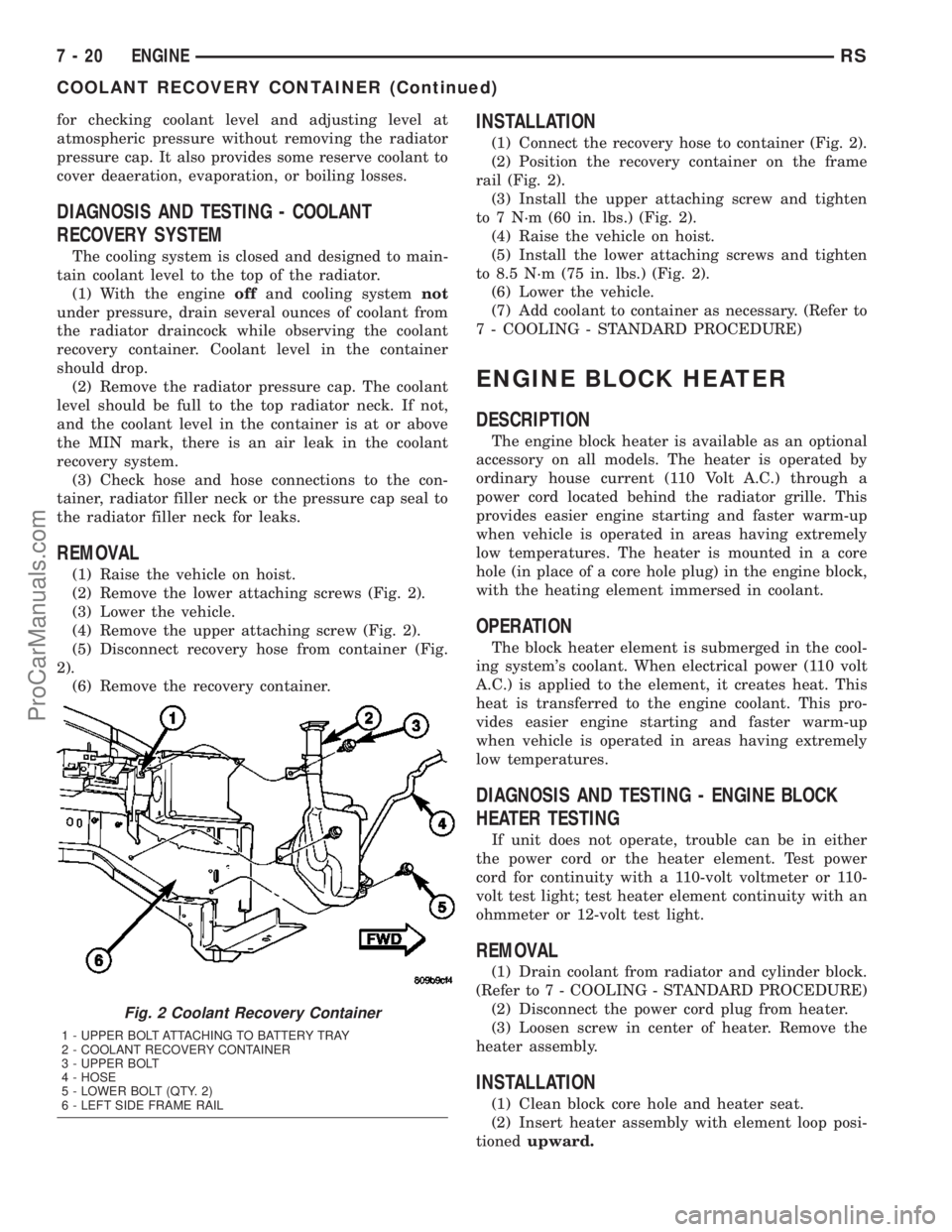
(2) Remove the lower attaching screws (Fig. 2).
(3) Lower the vehicle.
(4) Remove the upper attaching screw (Fig. 2).
(5) Disconnect recovery hose from container (Fig.
2).
(6) Remove the recovery container.
INSTALLATION
(1) Connect the recovery hose to container (Fig. 2).
(2) Position the recovery container on the frame
rail (Fig. 2).
(3) Install the upper attaching screw and tighten
to 7 N´m (60 in. lbs.) (Fig. 2).
(4) Raise the vehicle on hoist.
(5) Install the lower attaching screws and tighten
to 8.5 N´m (75 in. lbs.) (Fig. 2).
(6) Lower the vehicle.
(7) Add coolant to container as necessary. (Refer to
7 - COOLING - STANDARD PROCEDURE)
ENGINE BLOCK HEATER
DESCRIPTION
The engine block heater is available as an optional
accessory on all models. The heater is operated by
ordinary house current (110 Volt A.C.) through a
power cord located behind the radiator grille. This
provides easier engine starting and faster warm-up
when vehicle is operated in areas having extremely
low temperatures. The heater is mounted in a core
hole (in place of a core hole plug) in the engine block,
with the heating element immersed in coolant.
OPERATION
The block heater element is submerged in the cool-
ing system's coolant. When electrical power (110 volt
A.C.) is applied to the element, it creates heat. This
heat is transferred to the engine coolant. This pro-
vides easier engine starting and faster warm-up
when vehicle is operated in areas having extremely
low temperatures.
DIAGNOSIS AND TESTING - ENGINE BLOCK
HEATER TESTING
If unit does not operate, trouble can be in either
the power cord or the heater element. Test power
cord for continuity with a 110-volt voltmeter or 110-
volt test light; test heater element continuity with an
ohmmeter or 12-volt test light.
REMOVAL
(1) Drain coolant from radiator and cylinder block.
(Refer to 7 - COOLING - STANDARD PROCEDURE)
(2) Disconnect the power cord plug from heater.
(3) Loosen screw in center of heater. Remove the
heater assembly.
INSTALLATION
(1) Clean block core hole and heater seat.
(2) Insert heater assembly with element loop posi-
tionedupward.
Fig. 2 Coolant Recovery Container
1 - UPPER BOLT ATTACHING TO BATTERY TRAY
2 - COOLANT RECOVERY CONTAINER
3 - UPPER BOLT
4 - HOSE
5 - LOWER BOLT (QTY. 2)
6 - LEFT SIDE FRAME RAIL
7 - 20 ENGINERS
COOLANT RECOVERY CONTAINER (Continued)
ProCarManuals.com
Page 280 of 2177
(3) With heater seated, tighten center screw
securely to assure a positive seal.
(4) Install power cord plug to heater.
(5) Fill cooling system with coolant to the proper
level. (Refer to 7 - COOLING - STANDARD PROCE-
DURE)
ENGINE COOLANT
TEMPERATURE SENSOR - 2.4L
DESCRIPTION
The engine coolant temperature sensor threads
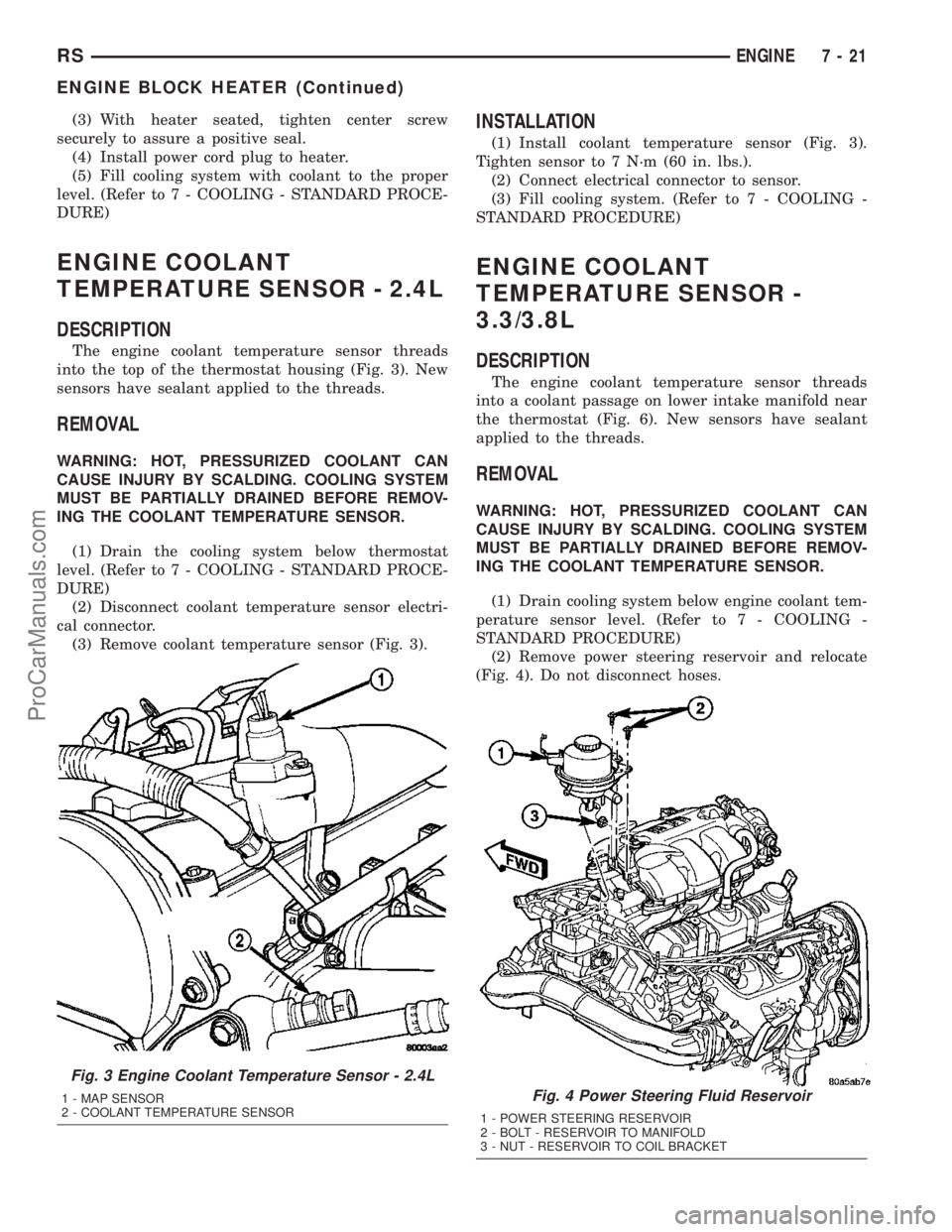
into the top of the thermostat housing (Fig. 3). New
sensors have sealant applied to the threads.
REMOVAL
WARNING: HOT, PRESSURIZED COOLANT CAN
CAUSE INJURY BY SCALDING. COOLING SYSTEM
MUST BE PARTIALLY DRAINED BEFORE REMOV-
ING THE COOLANT TEMPERATURE SENSOR.
(1) Drain the cooling system below thermostat
level. (Refer to 7 - COOLING - STANDARD PROCE-
DURE)
(2) Disconnect coolant temperature sensor electri-
cal connector.
(3) Remove coolant temperature sensor (Fig. 3).
INSTALLATION
(1) Install coolant temperature sensor (Fig. 3).
Tighten sensor to 7 N´m (60 in. lbs.).
(2) Connect electrical connector to sensor.
(3) Fill cooling system. (Refer to 7 - COOLING -
STANDARD PROCEDURE)
ENGINE COOLANT
TEMPERATURE SENSOR -
3.3/3.8L
DESCRIPTION
The engine coolant temperature sensor threads
into a coolant passage on lower intake manifold near
the thermostat (Fig. 6). New sensors have sealant
applied to the threads.
REMOVAL
WARNING: HOT, PRESSURIZED COOLANT CAN
CAUSE INJURY BY SCALDING. COOLING SYSTEM
MUST BE PARTIALLY DRAINED BEFORE REMOV-
ING THE COOLANT TEMPERATURE SENSOR.
(1) Drain cooling system below engine coolant tem-
perature sensor level. (Refer to 7 - COOLING -
STANDARD PROCEDURE)
(2) Remove power steering reservoir and relocate
(Fig. 4). Do not disconnect hoses.
Fig. 3 Engine Coolant Temperature Sensor - 2.4L
1 - MAP SENSOR
2 - COOLANT TEMPERATURE SENSORFig. 4 Power Steering Fluid Reservoir
1 - POWER STEERING RESERVOIR
2 - BOLT - RESERVOIR TO MANIFOLD
3 - NUT - RESERVOIR TO COIL BRACKET
RSENGINE7-21
ENGINE BLOCK HEATER (Continued)
ProCarManuals.com
Page 282 of 2177
DIAGNOSIS AND TESTING - ENGINE COOLANT
THERMOSTAT
The thermostat is operated by a wax filled cham-
ber (pellet) which is sealed. When heated coolant
reaches a predetermined temperature the wax pellet
expands enough to overcome the closing spring and
water pump pressure, which forces the valve to open.
Coolant leakage into the pellet will cause a thermo-
stat to fail open. Do not attempt to free up a thermo-
stat with a screwdriver.
Thermostat diagnostics is included in powertrain
control module's (PCM) programing for on-board
diagnosis. The malfunction indicator light (MIL) will
illuminate and a diagnostic trouble code (DTC) will
be set when an ªopen too soonº condition occurs. Do
not change a thermostat for lack of heater perfor-
mance or temperature gauge position, unless a DTC
is present. For other probable causes, (Refer to 7 -
COOLING/ENGINE - DIAGNOSIS AND TESTING).
Thermostat failing shut is the normal long term
mode of failure, and normally, only on high mileage
vehicles. The temperature gauge will indicate this
(Refer to 7 - COOLING/ENGINE - DIAGNOSIS AND
TESTING).
ENGINE COOLANT
THERMOSTAT - 2.4L
REMOVAL
(1) Drain cooling system below the thermostat
level. (Refer to 7 - COOLING - STANDARD PROCE-
DURE)
(2) Remove radiator upper hose from the coolant
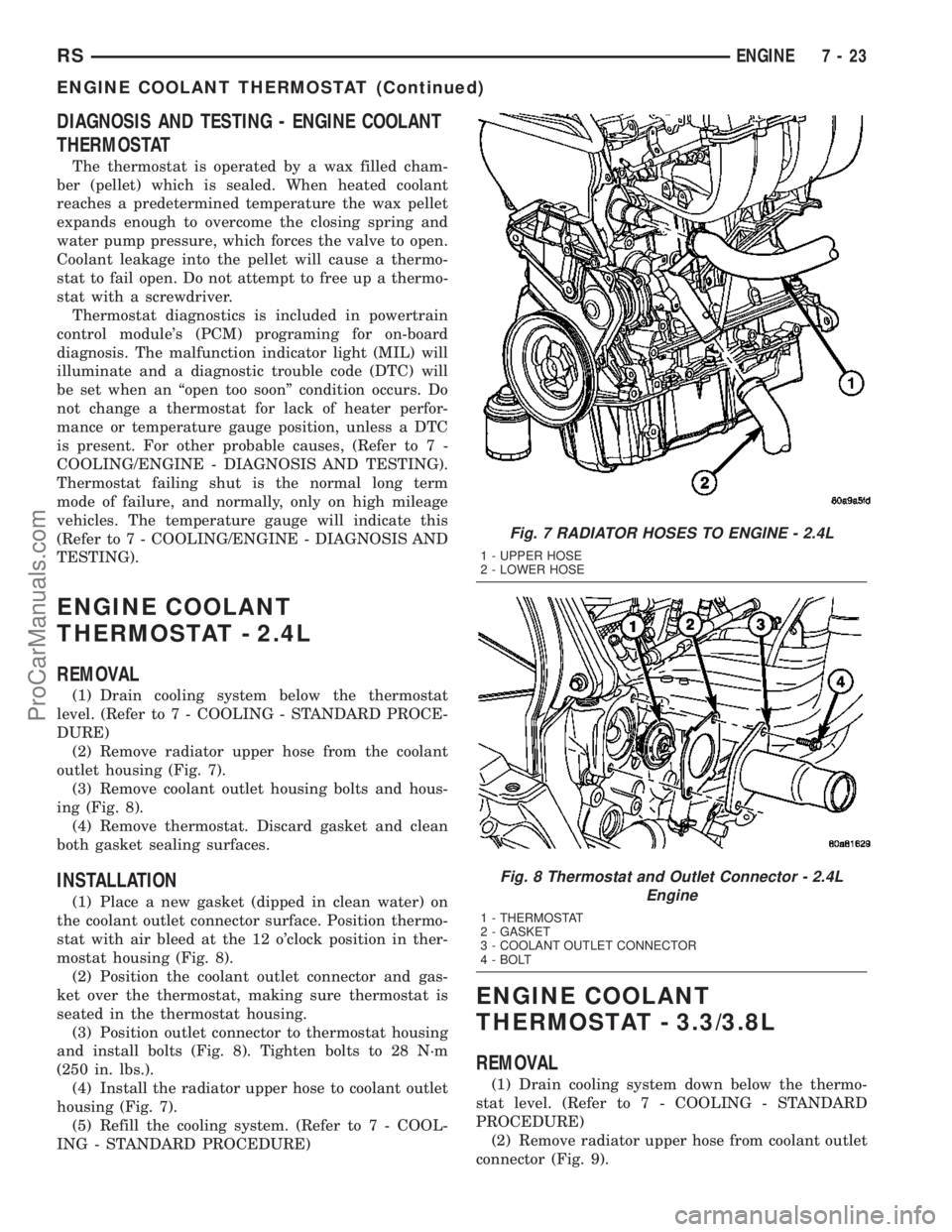
outlet housing (Fig. 7).
(3) Remove coolant outlet housing bolts and hous-
ing (Fig. 8).
(4) Remove thermostat. Discard gasket and clean
both gasket sealing surfaces.
INSTALLATION
(1) Place a new gasket (dipped in clean water) on
the coolant outlet connector surface. Position thermo-
stat with air bleed at the 12 o'clock position in ther-
mostat housing (Fig. 8).
(2) Position the coolant outlet connector and gas-
ket over the thermostat, making sure thermostat is
seated in the thermostat housing.
(3) Position outlet connector to thermostat housing
and install bolts (Fig. 8). Tighten bolts to 28 N´m
(250 in. lbs.).
(4) Install the radiator upper hose to coolant outlet
housing (Fig. 7).
(5) Refill the cooling system. (Refer to 7 - COOL-
ING - STANDARD PROCEDURE)
ENGINE COOLANT
THERMOSTAT - 3.3/3.8L
REMOVAL
(1) Drain cooling system down below the thermo-
stat level. (Refer to 7 - COOLING - STANDARD
PROCEDURE)
(2) Remove radiator upper hose from coolant outlet
connector (Fig. 9).
Fig. 7 RADIATOR HOSES TO ENGINE - 2.4L
1 - UPPER HOSE
2 - LOWER HOSE
Fig. 8 Thermostat and Outlet Connector - 2.4L
Engine
1 - THERMOSTAT
2 - GASKET
3 - COOLANT OUTLET CONNECTOR
4 - BOLT
RSENGINE7-23
ENGINE COOLANT THERMOSTAT (Continued)
ProCarManuals.com
Page 284 of 2177

(3) Position a new gasket over the thermostat and
connector making sure thermostat is in proper posi-
tion and in the recess provided.
(4) Install thermostat and connector assembly to
the intake manifold (Fig. 10). Tighten bolts to 28
N´m (250 in. lbs.).
(5) Install the radiator upper hose to coolant outlet
connector (Fig. 9).
(6) Refill the cooling system to the proper level.
(Refer to 7 - COOLING - STANDARD PROCEDURE)
RADIATOR
REMOVAL
(1) Disconnect negative cable from battery.
(2) Remove radiator upper crossmember support.
(Refer to 23 - BODY/EXTERIOR/GRILLE OPENING
REINFORCEMENT - REMOVAL)
WARNING: DO NOT REMOVE THE CYLINDER
BLOCK PLUG OR THE RADIATOR DRAINCOCK
WITH THE SYSTEM HOT AND UNDER PRESSURE
BECAUSE SERIOUS BURNS FROM COOLANT CAN
OCCUR.
(3) Drain the cooling system. (Refer to 7 - COOL-
ING - STANDARD PROCEDURE)
(4) Remove the radiator fans. (Refer to 7 - COOL-
ING/ENGINE/RADIATOR FAN - REMOVAL)
(5) Disconnect coolant reserve/recovery hose.
(6) Remove vapor purge solenoid from mounting
bracket.
(7) Disconnect upper and lower hoses from the
radiator (Fig. 13) or (Fig. 14).(8) Remove the A/C condenser side brackets to
radiator attaching screws (Fig. 15). Separate the con-
denser from the radiator by lifting upward to disen-
gage from lower mounts (Fig. 15). Allow the
condenser to rest in front of radiator.
(9) Radiator can now be lifted free from engine
compartment.Care should be taken not to dam-
age radiator cooling fins or water tubes during
removal.
INSTALLATION
(1)Be sure the air seal is in position before
radiator is installed.Slide radiator down into posi-
tion. Seat the radiator with the rubber isolators into
the mounting holes provided, with a 10 lbs. force.
(2) Position air conditioning condenser onto the
radiator lower mounts and install upper screws (Fig.
15). Tighten fasteners to 5 N´m (45 in. lbs.).
(3) Install the radiator upper and lower hoses (Fig.
13) or (Fig. 14).
(4) Connect the coolant reserve/recovery hose.
(5) Connect the vapor purge solenoid to the mount-
ing bracket.
(6) Install the radiator fans. (Refer to 7 - COOL-
ING/ENGINE/RADIATOR FAN - INSTALLATION)
(7) Install the radiator upper crossmember sup-
port. (Refer to 23 - BODY/EXTERIOR/GRILLE
OPENING REINFORCEMENT - INSTALLATION)
(8) Fill the cooling system. (Refer to 7 - COOLING
- STANDARD PROCEDURE)
(9) Connect negative cable to battery.
Fig. 13 Radiator Hoses to Radiator - 2.4L
1 - UPPER HOSE
2 - LOWER HOSE
3 - HOSE SUPPORT CLIP
Fig. 14 Radiator Hoses to Radiator - 3.3/3.8L
1 - UPPER HOSE
2 - LOWER HOSE
RSENGINE7-25
ENGINE COOLANT THERMOSTAT - 3.3/3.8L (Continued)
ProCarManuals.com
Page 290 of 2177

(3) Install closure panel and attaching screws.
(4) Connect negative cable to battery.
WATER PUMP - 2.4L
DESCRIPTION
The water pump has a cast aluminum body and
housing with a stamped steel impeller. The water
pump bolts directly to the block (Fig. 23). The cylin-
der block to water pump seal is provided by a rubber
O-ring. The water pump is driven by the engine tim-
ing belt.
REMOVAL
(1) Disconnect negative cable from battery.
(2) Raise vehicle on a hoist.
(3) Remove the right inner splash shield.
(4) Remove the accessory drive belts (Refer to 7 -
COOLING/ACCESSORY DRIVE/DRIVE BELTS -
REMOVAL).
(5) Drain the cooling system (Refer to 7 - COOL-
ING - STANDARD PROCEDURE).
(6) Support engine from the bottom and remove
right engine mount. (Refer to 9 - ENGINE/ENGINE
MOUNTING/RIGHT MOUNT - REMOVAL).
(7) Remove right engine mount bracket (Fig. 24).
(8) Remove the timing belt (Refer to 9 - ENGINE/
VALVE TIMING/TIMING BELT AND SPROCKET(S)
- REMOVAL).
Fig. 22 Radiator Fan Relay
1 - FRONT FASCIA
2 - FAN RELAY
3 - RIVET
4 - A/C CONDENSER (FRONT SIDE)
Fig. 23 Water Pump
1 - CYLINDER BLOCK
2 - WATER PUMP
RSENGINE7-31
RADIATOR FAN RELAY (Continued)
ProCarManuals.com
Page 292 of 2177
(7) Install the timing belt (Refer to 9 - ENGINE/
VALVE TIMING/TIMING BELT AND SPROCKET(S)
- INSTALLATION).
(8) Install the generator mount bracket. (Fig. 24)(9) Install the generator.
(10) Install right engine mount bracket and engine
mount (Refer to 9 - ENGINE/ENGINE MOUNTING/
RIGHT MOUNT - INSTALLATION).
(11) Fill the cooling system (Refer to 7 - COOLING
- STANDARD PROCEDURE).
(12) Install the accessory drive belts (Refer to 7 -
COOLING/ACCESSORY DRIVE/DRIVE BELTS -
INSTALLATION).
(13) Lower vehicle and connect battery cable.
WATER PUMP - 3.3/3.8L
DESCRIPTION
The water pump has a die-cast aluminum body
and a plastic impeller. It bolts directly to the timing
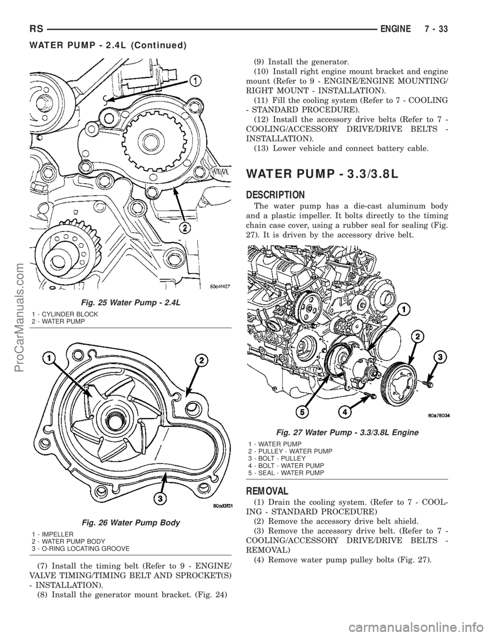
chain case cover, using a rubber seal for sealing (Fig.
27). It is driven by the accessory drive belt.
REMOVAL
(1) Drain the cooling system. (Refer to 7 - COOL-
ING - STANDARD PROCEDURE)
(2) Remove the accessory drive belt shield.
(3) Remove the accessory drive belt. (Refer to 7 -
COOLING/ACCESSORY DRIVE/DRIVE BELTS -
REMOVAL)
(4) Remove water pump pulley bolts (Fig. 27).
Fig. 25 Water Pump - 2.4L
1 - CYLINDER BLOCK
2 - WATER PUMP
Fig. 26 Water Pump Body
1 - IMPELLER
2 - WATER PUMP BODY
3 - O-RING LOCATING GROOVE
Fig. 27 Water Pump - 3.3/3.8L Engine
1 - WATER PUMP
2 - PULLEY - WATER PUMP
3 - BOLT - PULLEY
4 - BOLT - WATER PUMP
5 - SEAL - WATER PUMP
RSENGINE7-33
WATER PUMP - 2.4L (Continued)
ProCarManuals.com
Page 294 of 2177
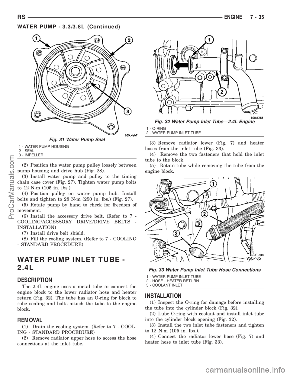
(2) Position the water pump pulley loosely between
pump housing and drive hub (Fig. 28).
(3) Install water pump and pulley to the timing
chain case cover (Fig. 27). Tighten water pump bolts
to 12 N´m (105 in. lbs.).
(4) Position pulley on water pump hub. Install
bolts and tighten to 28 N´m (250 in. lbs.) (Fig. 27).
(5) Rotate pump by hand to check for freedom of
movement.
(6) Install the accessory drive belt. (Refer to 7 -
COOLING/ACCESSORY DRIVE/DRIVE BELTS -
INSTALLATION)
(7) Install drive belt shield.
(8) Fill the cooling system. (Refer to 7 - COOLING
- STANDARD PROCEDURE)
WATER PUMP INLET TUBE -
2.4L
DESCRIPTION
The 2.4L engine uses a metal tube to connect the
engine block to the lower radiator hose and heater
return (Fig. 32). The tube has an O-ring for block to
tube sealing and bolts attach the tube to the engine
block.
REMOVAL
(1) Drain the cooling system. (Refer to 7 - COOL-
ING - STANDARD PROCEDURE)
(2) Remove radiator upper hose to access the hose
connections at the inlet tube.(3) Remove radiator lower (Fig. 7) and heater
hoses from the inlet tube (Fig. 33).
(4) Remove the two fasteners that hold the inlet
tube to the block.
(5) Rotate tube while removing the tube from the
engine block.
INSTALLATION
(1) Inspect the O-ring for damage before installing
the tube into the cylinder block (Fig. 32).
(2) Lube O-ring with coolant and install inlet tube
into the cylinder block opening (Fig. 32).
(3) Install the two inlet tube fasteners and tighten
to 12 N´m (105 in. lbs.).
(4) Connect the radiator lower hose (Fig. 7) and
heater hose to inlet tube (Fig. 33).
Fig. 31 Water Pump Seal
1 - WATER PUMP HOUSING
2 - SEAL
3 - IMPELLER
Fig. 32 Water Pump Inlet TubeÐ2.4L Engine
1 - O-RING
2 - WATER PUMP INLET TUBE
Fig. 33 Water Pump Inlet Tube Hose Connections
1 - WATER PUMP INLET TUBE
2 - HOSE - HEATER RETURN
3 - COOLANT INLET
RSENGINE7-35
WATER PUMP - 3.3/3.8L (Continued)
ProCarManuals.com
Page 295 of 2177
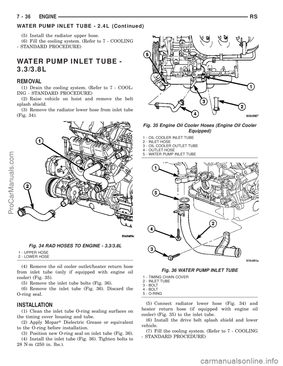
(5) Install the radiator upper hose.
(6) Fill the cooling system. (Refer to 7 - COOLING
- STANDARD PROCEDURE)
WATER PUMP INLET TUBE -
3.3/3.8L
REMOVAL
(1) Drain the cooling system. (Refer to 7 - COOL-
ING - STANDARD PROCEDURE)
(2) Raise vehicle on hoist and remove the belt
splash shield.
(3) Remove the radiator lower hose from inlet tube
(Fig. 34).
(4) Remove the oil cooler outlet/heater return hose
from inlet tube (only if equipped with engine oil
cooler) (Fig. 35).
(5) Remove the inlet tube bolts (Fig. 36).
(6) Remove the inlet tube (Fig. 36). Discard the
O-ring seal.
INSTALLATION
(1) Clean the inlet tube O-ring sealing surfaces on
the timing cover housing and tube.
(2) Apply MopartDielectric Grease or equivalent
to the O-ring before installation.
(3) Position new O-ring seal on inlet tube (Fig. 36).
(4) Install the inlet tube (Fig. 36). Tighten bolts to
28 N´m (250 in. lbs.).(5) Connect radiator lower hose (Fig. 34) and
heater return hose (if equipped with engine oil
cooler) (Fig. 35) to the inlet tube.
(6) Install the drive belt splash shield and lower
vehicle.
(7) Fill the cooling system. (Refer to 7 - COOLING
- STANDARD PROCEDURE)
Fig. 34 RAD HOSES TO ENGINE - 3.3/3.8L
1 - UPPER HOSE
2 - LOWER HOSE
Fig. 35 Engine Oil Cooler Hoses (Engine Oil Cooler
Equipped)
1 - OIL COOLER INLET TUBE
2 - INLET HOSE
3 - OIL COOLER OUTLET TUBE
4 - OUTLET HOSE
5 - WATER PUMP INLET TUBE
Fig. 36 WATER PUMP INLET TUBE
1 - TIMING CHAIN COVER
2 - INLET TUBE
3 - BOLT
4 - BOLT
5 - O-RING
7 - 36 ENGINERS
WATER PUMP INLET TUBE - 2.4L (Continued)
ProCarManuals.com
Page 357 of 2177

REMOVAL
The battery cables on this model may include por-
tions of wiring circuits for the generator and other
components on the vehicle. If battery cable replace-
ment is required, it will be necessary to extract the
cables out of the engine wire harness assembly. Use
care not to damage the other wires and circuits
which are also packaged into the engine wire harness
assembly.
(1) Turn the ignition switch to the Off position. Be
certain that all electrical accessories are turned off.
(2) Disconnect and isolate the negative battery
cable terminal.
(3) Remove the battery thermowrap (if equipped)
from the battery tray.
(4) Remove the tape from the engine wire harness
assembly, to access the desired battery cable.(5) One at a time, trace and disconnect the battery
cable retaining fasteners and routing clips until the
desired cable is free from the vehicle.
(6) Feed the battery cable out of the vehicle.
INSTALLATION
(1) Position the battery cable in the vehicle.
(2) One at a time, trace and install the battery
cable retaining fasteners and routing clips until the
desired cable is properly installed in the engine wire
harness assembly.
(3) Install the tape on the engine wire harness
assembly.
(4) Install the battery thermowrap (if equipped) on
the battery tray.
(5) Connect the negative battery cable terminal.
BATTERY TRAY
DESCRIPTION
The battery is mounted in a molded plastic battery
tray and support unit located in the left front corner
of the engine compartment. The battery tray and
support unit is secured with two nuts, one is located
directly under the battery and the other is located on
the right side of the tray which also serves as a cool-
ant bottle neck retaining bolt. An additional bolt is
located directly under the battery.
Fig. 15 Testing Battery Positive Cable Resistance
1 - BATTERY
2 - VOLTMETER
3 - STARTER MOTOR
Fig. 16 Testing Ground Circuit Resistance
1 - VOLTMETER
2 - BATTERY
3 - ENGINE GROUND
Fig. 17 RS BATTERY TRAY
1 - ENGINE VACUUM RESERVOIR
2 - BATTERY TRAY ASSEMBLY
3 - DRAINAGE HOSE
8F - 18 BATTERY SYSTEMRS
BATTERY CABLES (Continued)
ProCarManuals.com
Page 569 of 2177

INSTALLATION
(1) Connect the wire harness connector.
(2) Install the linkage on the wiper unit.
(3) Install the nut holding the linkage to the wiper
unit.
(4)
Install the cowl cover brackets to the wiper nut.
(5) Install the front wiper unit (Refer to 8 - ELEC-
TRICAL/WIPERS/WASHERS/WIPER MODULE -
INSTALLATION).
(6) Install the cowl cover.
(7) Install the wiper arms and blades.
WIPER MODULE
REMOVAL
(1) Release the hood latch and open hood.
(2) Disconnect and isolate the battery negative
cable.
(3) Remove the wiper arms.
(4) Remove the cowl cover (Refer to 23 - BODY/
EXTERIOR/COWL GRILLE - REMOVAL).
(5) Disconnect the positive lock on the wiper mod-
ule wire connector (Fig. 8).
(6) Disconnect the wiper module wire connector
from the engine compartment wire harness.
(7) Disconnect the windshield washer hose from
coupling outside the module.
(8) Disconnect the drain tubes from nipples on bot-
tom of the wiper module.
(9) Remove nuts holding wiper module to lower
windshield fence.
(10) Remove bolts holding the wiper module to the
dash panel (Fig. 9).(11) Lift wiper module from weld-studs on lower
windshield fence.
CAUTION: Do not allow wiper module to rest on
brake master cylinder reservoir, damage to brake
system can result.
(12) Remove wiper module.
INSTALLATION
(1) Position the wiper module into the cowl.
(2) Install the bolts that secure the wiper module
to the dash (Fig. 9).
(3) Install the nuts that retain the wiper module.
(4) Connect the drain tubes to the nipples on the
wiper module.
(5) Connect the windshield washer tube.
(6) Connect the wire harness connector to the
wiper module (Fig. 9).
(7) Connect the positive lock on the wiper module
wire connector (Fig. 8).
CAUTION: Do not allow wiper module to rest on
brake master cylinder reservoir, damage to brake
system can result.
(8) Install the cowl cover (Refer to 23 - BODY/EX-
TERIOR/COWL GRILLE - INSTALLATION).
(9) Install the wiper arms and blades.
(10) Connect the battery negative cable.
(11) Close the hood.
Fig. 8 WIPER MODULE WIRE CONNECTOR
1 - WIPER SYSTEM WIRE CONNECTOR
2 - LOCK TAB
3 - POSITIVE LOCK
4 - WIPER MODULE
Fig. 9 WIPER MODULE
1 - BOLT
2 - NUTS
3 - BOLT
4 - WIPER MODULE
5 - WINDSHIELD
8R - 18 WIPERS/WASHERSRS
WIPER LINKAGE (Continued)
ProCarManuals.com