wheel CHRYSLER CARAVAN 2003 Service Manual
[x] Cancel search | Manufacturer: CHRYSLER, Model Year: 2003, Model line: CARAVAN, Model: CHRYSLER CARAVAN 2003Pages: 2177, PDF Size: 59.81 MB
Page 1137 of 2177
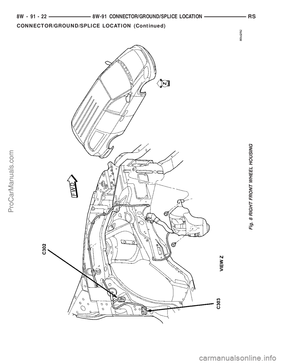
Fig. 8 RIGHT FRONT WHEEL HOUSING
8W - 91 - 22 8W-91 CONNECTOR/GROUND/SPLICE LOCATIONRS
CONNECTOR/GROUND/SPLICE LOCATION (Continued)
ProCarManuals.com
Page 1176 of 2177
to the fused B(+) fuse in the IPM that feeds the
accessories when the relay is energized by the igni-
tion switch. There should be continuity between the
IPM cavity for relay terminal 87 and the fused B(+)
fuse in the IPM at all times. If OK, go to Step 4. If
not OK, repair the open fused B(+) circuit to the IPM
fuse as required.
(4) The coil ground terminal (85) is connected to
the electromagnet in the relay. It receives battery
feed to energize the accessory relay when the ignition
switch is in the Accessory or On positions. Turn the
ignition switch to the On position. Check for battery
voltage at the fused ignition switch output (acc/run)
circuit cavity for relay terminal 85 in the IPM recep-
tacle for the accessory relay. If OK, go to Step 5. If
not OK, repair the open fused ignition switch output
(acc/run) circuit to the ignition switch as required.
(5) The coil battery terminal (86) is connected to
the electromagnet in the relay. The IPM cavity for
this terminal should have continuity to ground at all
times. If not OK, repair the open ground circuit to
ground as required.
REMOVAL
(1) Disconnect and isolate the battery negative
cable.
(2) Remove the Integrated Power Module (IPM)
cover from the IPM.
(3) Remove the accessory relay from the IPM.
Refer to the IPM cover for relay location.
INSTALLATION
(1) Position the accessory relay in the proper
receptacle in the Integrated Power Module (IPM).
(2) Push in firmly on the accessory relay until the
terminals are fully seated in the terminal cavities in
the IPM receptacle.
(3) Install the IPM cover.
(4) Reconnect the battery negative cable.
INTEGRATED POWER MODULE
DESCRIPTION
The Integrated Power Module (IPM) is a combina-
tion of the Power Distribution Center (PDC) and the
Front Control Module (FCM). The IPM is located in
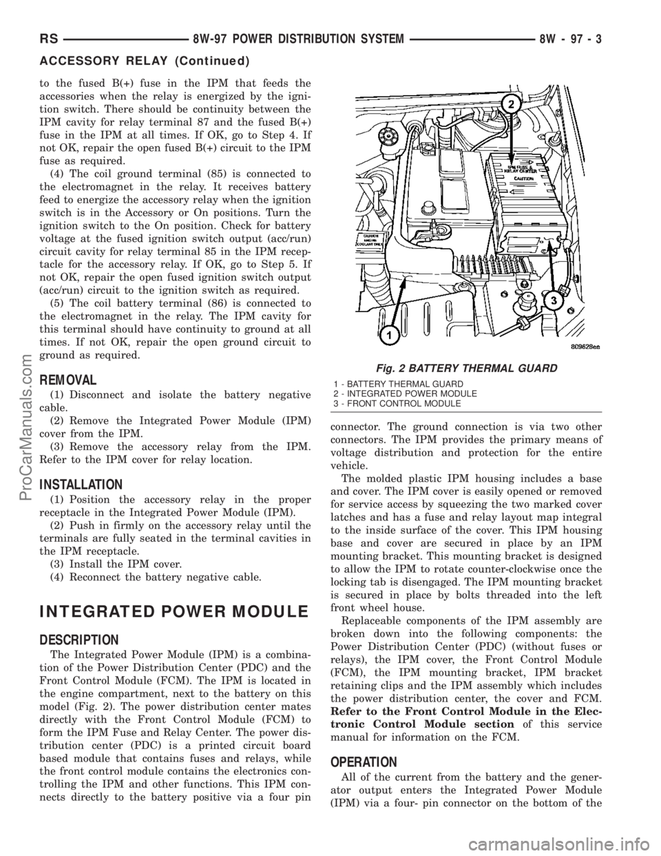
the engine compartment, next to the battery on this
model (Fig. 2). The power distribution center mates
directly with the Front Control Module (FCM) to
form the IPM Fuse and Relay Center. The power dis-
tribution center (PDC) is a printed circuit board
based module that contains fuses and relays, while
the front control module contains the electronics con-
trolling the IPM and other functions. This IPM con-
nects directly to the battery positive via a four pinconnector. The ground connection is via two other
connectors. The IPM provides the primary means of
voltage distribution and protection for the entire
vehicle.
The molded plastic IPM housing includes a base
and cover. The IPM cover is easily opened or removed
for service access by squeezing the two marked cover
latches and has a fuse and relay layout map integral
to the inside surface of the cover. This IPM housing
base and cover are secured in place by an IPM
mounting bracket. This mounting bracket is designed
to allow the IPM to rotate counter-clockwise once the
locking tab is disengaged. The IPM mounting bracket
is secured in place by bolts threaded into the left
front wheel house.
Replaceable components of the IPM assembly are
broken down into the following components: the
Power Distribution Center (PDC) (without fuses or
relays), the IPM cover, the Front Control Module
(FCM), the IPM mounting bracket, IPM bracket
retaining clips and the IPM assembly which includes
the power distribution center, the cover and FCM.
Refer to the Front Control Module in the Elec-
tronic Control Module sectionof this service
manual for information on the FCM.
OPERATION
All of the current from the battery and the gener-
ator output enters the Integrated Power Module
(IPM) via a four- pin connector on the bottom of the
Fig. 2 BATTERY THERMAL GUARD
1 - BATTERY THERMAL GUARD
2 - INTEGRATED POWER MODULE
3 - FRONT CONTROL MODULE
RS8W-97 POWER DISTRIBUTION SYSTEM8W-97-3
ACCESSORY RELAY (Continued)
ProCarManuals.com
Page 1179 of 2177
DIAGNOSIS AND TESTING
DIAGNOSIS & TESTING - POWER OUTLET
For complete circuit diagrams, refer toCigar
Lighter/Power Outletin Wiring Diagrams.
WARNING: ON VEHICLES EQUIPPED WITH AIR-
BAGS, REFER TO RESTRAINTS BEFORE ATTEMPT-
ING ANY STEERING WHEEL, STEERING COLUMN,
SEAT OR INSTRUMENT PANEL COMPONENT DIAG-
NOSIS OR SERVICE. FAILURE TO TAKE THE
PROPER PRECAUTIONS COULD RESULT IN ACCI-
DENTAL AIRBAG DEPLOYMENT AND POSSIBLE
PERSONAL INJURY.
(1) Check the fused B(+) fuse in the Integrated
Power Module (IPM). If OK, go to Step 2. If not OK,
repair the shorted circuit or component as required
and replace the faulty fuse.
(2) Check for battery voltage at the fused B(+) fuse
in the IPM. If OK, go to Step 3. If not OK, repair the
open fused B(+) circuit to the IPM fuse as required.
(3)
Open the power outlet door. Check for continuity
between the inside circumference of the power outlet
receptacle and a good ground. There should be continu-
ity. If OK, go to Step 4. If not OK, go to Step 5.
(4) Check for battery voltage at the insulated con-
tact located at the back of the power outlet recepta-
cle. If not OK, go to Step 5.
(5) Disconnect and isolate the battery negative
cable. Remove the appropriate bezel. Check for conti-
nuity between the ground circuit cavity of the power
outlet wire harness connector and a good ground.
There should be continuity. If OK, go to Step 6. If not
OK, repair the open ground circuit to ground as
required.
(6) Connect the battery negative cable. Check for
battery voltage at the fused B(+) circuit cavity of the
power outlet wire harness connector. If OK, replace
the faulty power outlet receptacle. If not OK, repair
the open fused B(+) circuit to the IPM fuse as
required.
REMOVAL
(1)Disconnect and isolate the battery negative cable.
(2) Look inside and note position of the retaining
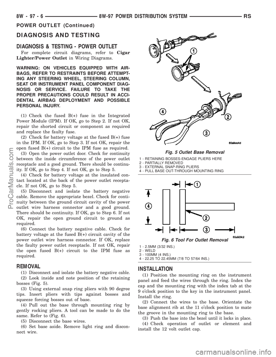
bosses (Fig. 5).
(3) Using external snap ring pliers with 90 degree
tips. Insert pliers with tips against bosses and
squeeze forcing bosses out of base.
(4) Pull out the base through mounting ring by
gently rocking pliers. A tool can be made to do the
same. Refer to (Fig. 6).
(5) Disconnect the base wires.
(6) Set base aside. Remove light ring and discon-
nect wire.
INSTALLATION
(1) Position the mounting ring on the instrument
panel and feed the wires through the ring. Index the
cap and the mounting ring with the index tab at the
9 o'clock position to the key in the instrument panel.
Install the ring.
(2) Connect the wires to the base. Orientate the
base alignment rib at the 11 o'clock position to mate
the groove in the mounting ring to the base.
(3)
Push the base into the bezel until it locks in place.
(4) Check operation of outlet or element and
install the 12 volt outlet cap.
Fig. 5 Outlet Base Removal
1 - RETAINING BOSSES-ENGAGE PLIERS HERE
2 - PARTIALLY REMOVED
3 - EXTERNAL SNAP-RING PLIERS
4 - PULL BASE OUT-THROUGH MOUNTING RING
Fig. 6 Tool For Outlet Removal
1 - 2.5MM (3/32 INS.)
2 - WELD
3 - 100MM (4 INS.)
4 - 22.25 TO 22.45MM (7/8 TO 57/64 INS.)
8W - 97 - 6 8W-97 POWER DISTRIBUTION SYSTEMRS
POWER OUTLET (Continued)
ProCarManuals.com
Page 1182 of 2177

TIMING BELT AND SPROCKET(S)
REMOVAL
REMOVAL - TIMING BELT...............63
REMOVAL - CAMSHAFT SPROCKETS.....64
REMOVAL - CRANKSHAFT SPROCKET....64
CLEANING............................64
INSTALLATION
INSTALLATION - CRANKSHAFT SPROCKET . 65
INSTALLATION - CAMSHAFT SPROCKETS . . 65INSTALLATION - TIMING BELT...........65
TIMING BELT TENSIONER & PULLEY
REMOVAL.............................68
INSTALLATION.........................69
BALANCE SHAFTS AND CARRIER ASSEMBLY
DESCRIPTION.........................69
OPERATION...........................69
REMOVAL.............................69
INSTALLATION.........................72
ENGINE 2.4L
DESCRIPTION
The 2.4 Liter (148 cu. in.) in-line four cylinder
engine is a double over head camshaft with hydraulic
lash adjusters and four valve per cylinder design.
The engine is free-wheeling; meaning it has provi-
sions for piston-to-valve clearance. However valve-to-
valve interference can occur, if camshafts are rotated
independently.
The cylinders are numbered from front of the
engine to the rear. The firing order is 1±3±4±2.
The engine identification number is located on the
rear of the cylinder block (Fig. 1).
DIAGNOSIS AND TESTING
DIAGNOSIS AND TESTING - ENGINE
DIAGNOSIS - INTRODUCTION
Engine diagnosis is helpful in determining the
causes of malfunctions not detected and remedied by
routine maintenance.
These malfunctions may be classified as either
mechanical (e.g., a strange noise), or performance
(e.g., engine idles rough and stalls).
Refer to the Engine Mechanical and the Engine
Performance diagnostic charts, for possible causes
and corrections of malfunctions (Refer to 9 - ENGINE
- DIAGNOSIS AND TESTING - MECHANICAL)
(Refer to 9 - ENGINE - DIAGNOSIS AND TESTING
- PERFORMANCE).
For fuel system diagnosis, (Refer to 14 - FUEL
SYSTEM/FUEL DELIVERY - DIAGNOSIS AND
TESTING).
Additional tests and diagnostic procedures may be
necessary for specific engine malfunctions that can-
not be isolated with the Service Diagnosis charts.
Information concerning additional tests and diagno-
sis is provided within the following:
²Cylinder Compression Pressure Test
²Cylinder Combustion Pressure Leakage Test
²Engine Cylinder Head Gasket Failure Diagnosis
²Intake Manifold Leakage Diagnosis
²Hydraulic Lash Adjuster Noise Diagnosis
²Engine Oil Leak Inspection
Fig. 1 Engine Identification
1 - ENGINE IDENTIFICATION LOCATION
RSENGINE 2.4L9-3
ProCarManuals.com
Page 1186 of 2177

CONDITION POSSIBLE CAUSES CORRECTION
MAIN BEARING NOISE 1. Insufficient oil supply. 1. Check engine oil level.
2. Low oil pressure. 2. Check engine oil level. Inspect oil
pump relief valve and spring.
3. Thin or diluted oil. 3. Change oil to correct viscosity.
4. Thick oil 4. (a) Change engine oil and filter.
(b) Run engine to operating
temperature.
(c) Change engine oil and filter
again.
5. Excessive bearing clearance. 5. Measure bearings for correct
clearance. Repair as necessary.
6. Excessive end play. 6. Check thrust bearing for wear on
flanges.
7. Crankshaft journal out-of-round
or worn.7. Replace crankshaft or grind
journals.
8. Loose flywheel or torque
converter.8. Tighten to correct torque.
OIL PRESSURE DROP 1. Low oil level. 1. Check engine oil level.
2. Faulty oil pressure sensor/switch. 2. Replace oil pressure sensor/
switch.
3. Low oil pressure. 3. Check oil pressure sensor/switch
and main bearing oil clearance.
4. Clogged oil filter. 4. Install new oil filter.
5. Worn parts in oil pump. 5. Replace worn parts or pump.
6. Thin or diluted oil. 6. Change oil to correct viscosity.
7. Oil pump relief valve stuck. 7. Remove valve and inspect, clean,
or replace.
8. Oil pump suction tube loose. 8. Remove oil pan and install new
tube or clean, if necessary.
9. Oil pump cover warped or
cracked.9. Install new oil pump.
10. Excessive bearing clearance. 10. Measure bearings for correct
clearance.
OIL LEAKS 1. Misaligned or deteriorated
gaskets.1. Replace gasket(s).
2. Loose fastener, broken or porous
metal part.2. Tighten, repair or replace the
part.
3. Misaligned or deteriorated cup or
threaded plug.3. Replace as necessary.
RSENGINE 2.4L9-7
ENGINE 2.4L (Continued)
ProCarManuals.com
Page 1192 of 2177

REMOVAL - ENGINE ASSEMBLY
(1) Perform fuel pressure release procedure (Refer
to 14 - FUEL SYSTEM/FUEL DELIVERY - STAN-
DARD PROCEDURE)
(2) Disconnect battery negative cable.
(3) Remove air cleaner housing and inlet tube.
(4) Disconnect the fuel line from fuel rail. (Refer to
14 - FUEL SYSTEM/FUEL DELIVERY/FUEL LINES
- STANDARD PROCEDURE)
(5) Disconnect all vacuum hoses.
(6) Drain cooling system. (Refer to 7 - COOLING -
STANDARD PROCEDURE)
(7) Remove radiator fans. (Refer to 7 - COOLING/
ENGINE/RADIATOR FAN - REMOVAL)
(8) Remove radiator upper and lower hoses.
NOTE: When the transaxle cooler lines are removed
from the rolled-groove type fittings at the transaxle,
damage to the inner wall of the hose will occur. To
prevent prevent potential leakage, the cooler hoses
must be cut off flush at the transaxle fitting, and a
service cooler hose splice kit must be installed
upon reassembly.(9) Using a blade or suitable hose cutter, cut trans-
axle oil cooler lines off flush with fittings. Plug cooler
lines and fittings to prevent debris from entering
transaxle or cooler circuit. A service splice kit will be
installed upon reassembly.
(10) Disconnect transmission shift linkage and
electrical connectors.
(11) Disconnect throttle body linkage.
(12) Disconnect engine wiring harness.
(13) Disconnect heater hoses from heater (Fig. 5).
(14) Discharge air conditioning system. (Refer to
24 - HEATING & AIR CONDITIONING/PLUMBING
- STANDARD PROCEDURE)
(15) Hoist vehicle and remove front wheels and
tires.
(16) Remove accessory drive belt splash shield.
(17) Remove accessory drive belts. (Refer to 7 -
COOLING/ACCESSORY DRIVE/DRIVE BELTS -
REMOVAL)
Fig. 5 HEATER HOSES - 2.4L
1 - HEATER HOSES TO HEATER 3 - HEATER HOSE TO ENGINE - SUPPLY AND RETURN
2 - BOLT - HEATER TUBE SUPPORT
RSENGINE 2.4L9-13
ENGINE 2.4L (Continued)
ProCarManuals.com
Page 1195 of 2177
INSTALLATION - ENGINE ASSEMBLY
(1) Position engine and transmission assembly
under vehicle and slowly lower the vehicle over the
engine and transmission.
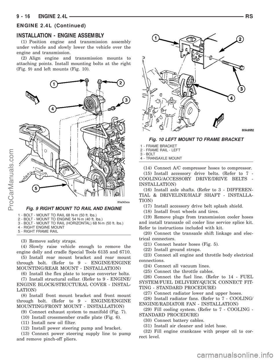
(2) Align engine and transmission mounts to
attaching points. Install mounting bolts at the right
(Fig. 9) and left mounts (Fig. 10).
(3) Remove safety straps.
(4) Slowly raise vehicle enough to remove the
engine dolly and cradle Special Tools 6135 and 6710.
(5) Install rear mount bracket and rear mount
through bolt. (Refer to 9 - ENGINE/ENGINE
MOUNTING/REAR MOUNT - INSTALLATION)
(6) Install the flex plate to torque converter bolts.
(7) Install structural collar. (Refer to 9 - ENGINE/
ENGINE BLOCK/STRUCTURAL COVER - INSTAL-
LATION)
(8) Install front mount bracket and front mount
through bolt. (Refer to 9 - ENGINE/ENGINE
MOUNTING/FRONT MOUNT - INSTALLATION)
(9) Connect exhaust system to manifold (Fig. 7).
(10) Install crossmember cradle plate (Fig. 6).
(11) Install new oil filter.
(12) Install power steering pump and bracket.
(13) Connect power steering supply line to pump
and remove pinch-off pliers.(14) Connect A/C compressor hoses to compressor.
(15) Install accessory drive belts. (Refer to 7 -
COOLING/ACCESSORY DRIVE/DRIVE BELTS -
INSTALLATION)
(16) Install axle shafts. (Refer to 3 - DIFFEREN-
TIAL & DRIVELINE/HALF SHAFT - INSTALLA-
TION)
(17) Install accessory drive belt splash shield.
(18) Install front wheels and tires.
(19) Remove plugs from transmission cooler hoses
and install transaxle oil cooler line service splice kit.
Refer to instructions included with kit.
(20) Connect the transaxle shift linkage and elec-
trical connectors.
(21) Connect heater hoses (Fig. 5).
(22) Install ground straps.
(23) Connect all engine and throttle body electrical
connections.
(24) Connect all vacuum lines.
(25) Connect the throttle cables.
(26) Connect the fuel line. (Refer to 14 - FUEL
SYSTEM/FUEL DELIVERY/QUICK CONNECT FIT-
TING - STANDARD PROCEDURE)
(27) Connect radiator lower and upper hoses.
(28) Install radiator fans. (Refer to 7 - COOLING/
ENGINE/RADIATOR FAN - INSTALLATION)
(29) Fill cooling system. (Refer to 7 - COOLING -
STANDARD PROCEDURE)
(30) Connect battery cables.
(31) Install air cleaner and inlet hose.
(32) Fill engine crankcase with proper oil to cor-
rect level.
Fig. 9 RIGHT MOUNT TO RAIL AND ENGINE
1 - BOLT - MOUNT TO RAIL 68 N´m (50 ft. lbs.)
2 - BOLT - MOUNT TO ENGINE 54 N´m (40 ft. lbs.)
3 - BOLT - MOUNT TO RAIL (HORIZONTAL) 68 N´m (50 ft. lbs.)
4 - RIGHT ENGINE MOUNT
5 - RIGHT FRAME RAIL
Fig. 10 LEFT MOUNT TO FRAME BRACKET
1 - FRAME BRACKET
2 - FRAME RAIL - LEFT
3 - BOLT
4 - TRANSAXLE MOUNT
9 - 16 ENGINE 2.4LRS
ENGINE 2.4L (Continued)
ProCarManuals.com
Page 1216 of 2177

(4) Move crankshaft all the way to the front and
read the dial indicator. Refer to Engine Specifica-
tions.
REMOVAL - CRANKSHAFT
NOTE: Crankshaft can not be removed when engine
is in vehicle.
(1) Remove engine assembly from vehicle (Refer to
9 - ENGINE - REMOVAL).
(2) Separate transaxle from engine.
(3) Remove drive plate/flex plate.
(4) Remove crankshaft rear oil seal (Refer to 9 -
ENGINE/ENGINE BLOCK/CRANKSHAFT OIL
SEAL - REAR - REMOVAL).
(5) Mount engine on a suitable repair stand.
(6) Drain engine oil and remove oil filter.
(7) Remove crankshaft vibration damper (Refer to
9 - ENGINE/ENGINE BLOCK/VIBRATION
DAMPER - REMOVAL).
(8) Remove engine mount support bracket.
(9) Remove front timing belt covers (Refer to 9 -
ENGINE/VALVE TIMING/TIMING BELT COVER(S)
- REMOVAL).
(10) Remove the timing belt (Refer to 9 - ENGINE/
VALVE TIMING/TIMING BELT AND SPROCKETS -
REMOVAL).
(11) Remove the oil pan (Refer to 9 - ENGINE/LU-
BRICATION/OIL PAN - REMOVAL).
(12) Remove oil pump pick-up tube.
(13) Remove the crankshaft sprocket and oil pump
(Refer to 9 - ENGINE/LUBRICATION/OIL PUMP -
REMOVAL).
(14) Remove balance shafts and housing assembly
(Refer to 9 - ENGINE/VALVE TIMING/BALANCE
SHAFT - REMOVAL).
(15) Remove crankshaft position sensor.NOTE: If piston/connecting rod replacement is nec-
essary, remove cylinder head (Refer to 9 - ENGINE/
CYLINDER HEAD - REMOVAL).
(16) Using a permanent ink or paint marker, iden-
tify cylinder number on each connecting rod cap (Fig.
44).
CAUTION: DO NOT use a number stamp or a punch
to mark connecting rods. Damage to connecting
rod could occur.
(17) Remove all connecting rod bolts and caps.
Care should be taken not to damage the fracture rod
and cap surfaces.
NOTE: Do not reuse connecting rod bolts.
(18) Remove all bedplate bolts from the engine
block (Fig. 45).
(19) Using a mallet gently tap the bedplate loose
from the engine block dowel pins.
CAUTION: Do not pry up on one side of the bed-
plate. Damage may occur to cylinder block to bed-
plate alignment and thrust bearing.
(20) Bedplate should be removed evenly from the
cylinder block dowel pins to prevent damage to the
dowel pins and thrust bearing.
CAUTION: Use extreme care when handling crank-
shaft. Tone wheel damage can occur if crankshaft is
mis-handled.
(21) Lift out crankshaft from cylinder block. Do
not damage the main bearings or journals when
removing the crankshaft.
INSPECTION
For crankshaft specifications (Refer to 9 - ENGINE
- SPECIFICATIONS).
Fig. 43 CHECKING CRANKSHAFT END PLAY
Fig. 44 Identify Connecting Rod to Cylinder
RSENGINE 2.4L9-37
CRANKSHAFT (Continued)
ProCarManuals.com
Page 1228 of 2177
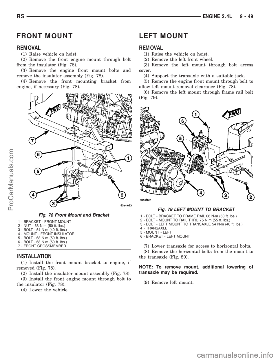
FRONT MOUNT
REMOVAL
(1) Raise vehicle on hoist.
(2) Remove the front engine mount through bolt
from the insulator (Fig. 78).
(3) Remove the engine front mount bolts and
remove the insulator assembly (Fig. 78).
(4) Remove the front mounting bracket from
engine, if necessary (Fig. 78).
INSTALLATION
(1) Install the front mount bracket to engine, if
removed (Fig. 78).
(2) Install the insulator mount assembly (Fig. 78).
(3) Install the front engine mount through bolt to
the insulator (Fig. 78).
(4) Lower the vehicle.
LEFT MOUNT
REMOVAL
(1) Raise the vehicle on hoist.
(2) Remove the left front wheel.
(3) Remove the left mount through bolt access
cover.
(4) Support the transaxle with a suitable jack.
(5) Remove the engine front mount through bolt to
allow left mount removal clearance (Fig. 78).
(6) Remove the left mount through frame rail bolt
(Fig. 79).
(7) Lower transaxle for access to horizontal bolts.
(8) Remove the horizontal bolts from the mount to
the transaxle (Fig. 80).
NOTE: To remove mount, additional lowering of
transaxle may be required.
(9) Remove left mount.
Fig. 78 Front Mount and Bracket
1 - BRACKET - FRONT MOUNT
2 - NUT - 68 N´m (50 ft. lbs.)
3 - BOLT - 54 N´m (40 ft. lbs.)
4 - MOUNT - FRONT INSULATOR
5 - BOLT - 68 N´m (50 ft. lbs.)
6 - BOLT - 68 N´m (50 ft. lbs.)
7 - FRONT CROSSMEMBER
Fig. 79 LEFT MOUNT TO BRACKET
1 - BOLT - BRACKET TO FRAME RAIL 68 N´m (50 ft. lbs.)
2 - BOLT - MOUNT TO RAIL THRU 75 N´m (55 ft. lbs.)
3 - BOLT - LEFT MOUNT TO TRANSAXLE 54 N´m (40 ft. lbs.)
4 - TRANSAXLE
5 - MOUNT - LEFT
6 - BRACKET - LEFT MOUNT
RSENGINE 2.4L9-49
ProCarManuals.com
Page 1229 of 2177

INSTALLATION
(1) Install left mount on transaxle (Fig. 80).
(2) Raise transaxle with jack until left mount is in
position.
(3) Install left mount through bolt (Fig. 79).
(4) Install left mount through bolt access cover.
(5) Install front mount through bolt (Fig. 78).
(6) Install left front wheel.
(7) Lower vehicle.
REAR MOUNT
REMOVAL
(1) Raise vehicle on hoist.
(2) Remove the rear mount heat shield (Fig. 81).
(3) Remove the through bolt from the mount and
rear mount bracket (Fig. 82).
(4) Remove the mount bolts (Fig. 82).
(5) Remove the rear mount (Fig. 82).
(6) For rear mount bracket removal, remove the
bolts attaching bracket to transaxle (Fig. 83).
(7) Remove rear mount bracket.
INSTALLATION
(1) Install rear mount bracket, if removed (Fig.
83).
(2) Install the rear mount and bolts (Fig. 82).
Tighten bolts to 54 N´m (40 ft. lbs.).(3) Install the mount through bolt to the mount
and bracket (Fig. 82). Tighten through bolt to 54 N´m
(40 ft. lbs.).
(4) Install the rear mount heat shield (Fig. 81).
(5) Lower vehicle on hoist.
Fig. 80 LEFT MOUNT - 41TE TRANSAXLE
1 - LEFT MOUNT ASSEMBLY
2 - BOLT - 54 N´m (40 ft. lbs.)
3 - TRANSAXLE - 41TE
Fig. 81 REAR MOUNT HEAT SHIELD
1 - BOLT - HEAT SHIELD 11 N´m (100 in. lbs.)
2 - HEAT SHIELD
3 - CLIP
4 - REAR MOUNT
Fig. 82 REAR MOUNT
1 - BOLT 54 N´m (40 ft. lbs.)
2 - REAR MOUNT BRACKET
3 - THRU-BOLT 54 N´m (40 ft. lbs.)
4 - REAR MOUNT
9 - 50 ENGINE 2.4LRS
LEFT MOUNT (Continued)
ProCarManuals.com