ors CHRYSLER CARAVAN 2005 Owners Manual
[x] Cancel search | Manufacturer: CHRYSLER, Model Year: 2005, Model line: CARAVAN, Model: CHRYSLER CARAVAN 2005Pages: 2339, PDF Size: 59.69 MB
Page 356 of 2339
(3) Install the center bezel onto the instrument
panel, (Refer to 23 - BODY/INSTRUMENT PANEL/
INSTRUMENT PANEL CENTER BEZEL - INSTAL-
LATION).
(4) Connect the battery negative cable.
HEATED SEAT ELEMENTS
DESCRIPTION
The heated seat system includes two seat heating
elements in each front seat, one for the seat cushion
and the other for the seat back. The two elements for
each seat that are connected in series with the
Heated Seat Module (HSM). The temperature sensor
is a Negative Temperature Coefficient (NTC) ther-
mistor. One temperature sensor is used for each seat,
and it is located on the seat cushion heating element
for all models.
The seat heating elements are attached to the seat
cushion cover trim and seat back cover trim units.
The heated seat elements and the temperature sen-
sor cannot be adjusted or repaired and, if faulty or
damaged, the seat element assembly must be
replaced, (Refer to 8 - ELECTRICAL/HEATED
SEATS/HEATED SEAT ELEMENT - REMOVAL).
OPERATION
The heated seat elements resist the flow of electri-
cal current. When battery current is passed through
the elements, the resistance of the elements to the
current flow is released in the form of heat. The tem-
perature sensor is a Negative Temperature Coeffi-
cient (NTC) thermistor. When the temperature of the
seat cushion cover rises, the resistance of the sensor
decreases. The heated seat module supplies a five-
volt signal to one side of each sensor, and monitors
the voltage drop through the sensor on a return cir-
cuit. The heated seat module uses this temperature
sensor input to monitor the temperature of the seat,
and regulates the current flow to the seat heating
elements accordingly.
DIAGNOSIS AND TESTING
HEATED SEAT ELEMENTS
The wire harness connectors for the seat cushion
and seat back heating elements are located under the
seat, at the heated seat module. Refer to the appro-
priate wiring information for complete circuit sche-
matic or connector pin-out information.
In order to access and test the heated seat ele-
ments it will be necessary to remove the appropriate
front seat retaining bolts and lay the seat rearward,
up against one of the rear seats. It is not necessary
to disconnect the seat electrical connectors, just use
care not to damage the attached wire harnesses
while testing.
NOTE: When checking heated seat elements for
continuity, be certain to move the heating element
being checked. Moving the element, such as sitting
in the seat will eliminate the possibility of an inter-
mittent open in the element which would only be
evident if the element was in a certain position.
Failure to check the element in various positions
could result in an incomplete test.
SEAT CUSHION ELEMENT
(1) From under the vehicle, remove the appropri-
ate seats four retaining nuts.
(2) From inside the vehicle, pull the seat up, off
the mounting studs and lay it back, up against one of
the rear seats.
(3) Locate the heated seat module, attached to the
bottom of the seat cushion pan. Remove the heated
seat module from the seat cushion pan. Do not dis-
connect the electrical connectors at this time.
(4) Locate and disconnect the green 4-way electri-
cal connector, connected to the heated seat module.
(5) Check for continuity between the two outboard
circuit cavities of the wire harness connector (Pins
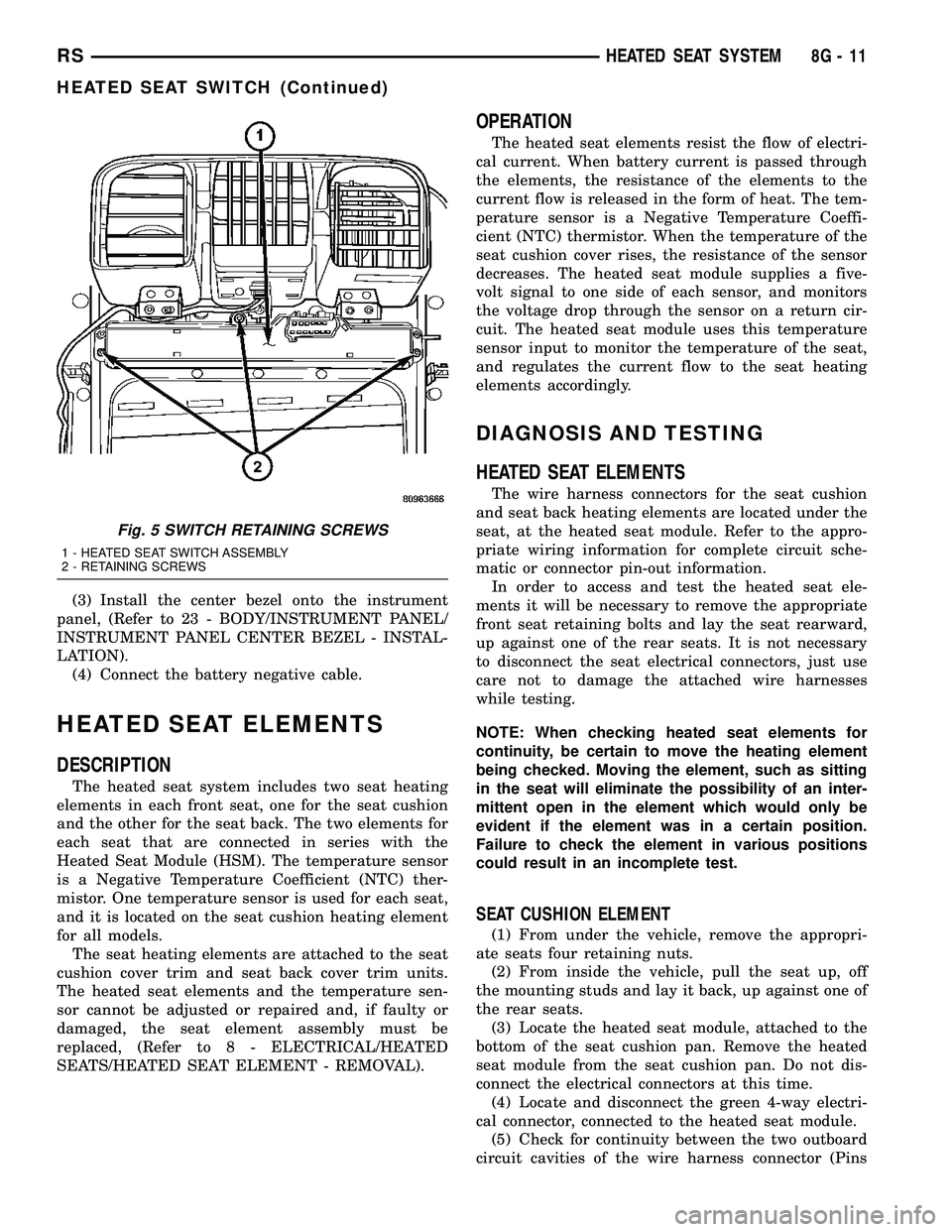
Fig. 5 SWITCH RETAINING SCREWS
1 - HEATED SEAT SWITCH ASSEMBLY
2 - RETAINING SCREWS
RSHEATED SEAT SYSTEM8G-11
HEATED SEAT SWITCH (Continued)
Page 357 of 2339
1&4). There should be continuity. If OK, (Refer to 8 -
ELECTRICAL/ELECTRONIC CONTROL MOD-
ULES/MEMORY HEATED SEAT/MIRROR MOD-
ULE - DIAGNOSIS AND TESTING) for complete
system testing procedures. If not OK, install a
replacement heated seat cushion element, (Refer to 8
- ELECTRICAL/HEATED SEATS/HEATED SEAT
ELEMENT - INSTALLATION).
SEAT BACK ELEMENT
(1) From under the vehicle, remove the appropri-
ate seats four retaining nuts.
(2) From inside the vehicle, pull the seat up and
off the mounting studs and lay it back, up against
one of the rear seats.
(3) Locate the heated seat module, attached to the
bottom of the seat cushion pan. Remove the heated
seat module from the seat cushion pan. Do not dis-
connect the electrical connectors at this time.
(4) Locate and disconnect the gray 2-way electrical
connector, connected to the heated seat module.
(5) Check for continuity between the two circuit
cavities of the 2-way wire harness connector. There
should be continuity. If OK, (Refer to 8 - ELECTRI-
CAL/ELECTRONIC CONTROL MODULES/MEM-
ORY HEATED SEAT/MIRROR MODULE -
DIAGNOSIS AND TESTING) for complete system
testing procedures. If not OK, install a replacement
heated seat back element, (Refer to 8 - ELECTRI-
CAL/HEATED SEATS/HEATED SEAT ELEMENT -
INSTALLATION).
REMOVAL
NOTE: Do not remove the factory installed heating
elements from the seat or seat back cushions. The
original element is permanently attached and can-
not be removed without permanent damage. The
replacement heating element is designed to be
applied directly on top of the factory installed heat-
ing element.
(1) Disconnect and isolate the battery negative
cable.
(2) Remove the appropriate seat cushion or seat
back trim cover.
(3) Disconnect the inoperative heated seat cushion
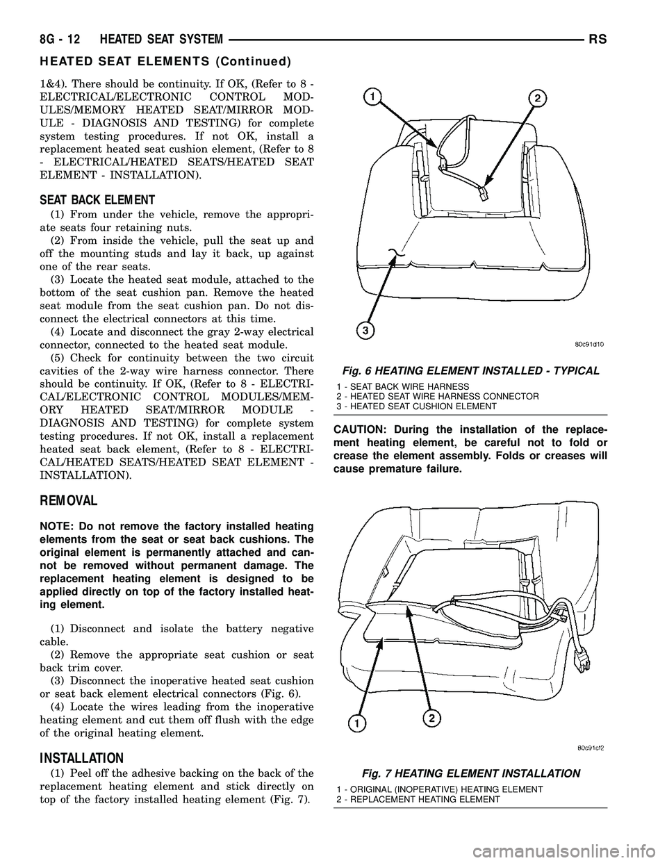
or seat back element electrical connectors (Fig. 6).
(4) Locate the wires leading from the inoperative
heating element and cut them off flush with the edge
of the original heating element.
INSTALLATION
(1) Peel off the adhesive backing on the back of the
replacement heating element and stick directly on
top of the factory installed heating element (Fig. 7).CAUTION: During the installation of the replace-
ment heating element, be careful not to fold or
crease the element assembly. Folds or creases will
cause premature failure.
Fig. 6 HEATING ELEMENT INSTALLED - TYPICAL
1 - SEAT BACK WIRE HARNESS
2 - HEATED SEAT WIRE HARNESS CONNECTOR
3 - HEATED SEAT CUSHION ELEMENT
Fig. 7 HEATING ELEMENT INSTALLATION
1 - ORIGINAL (INOPERATIVE) HEATING ELEMENT
2 - REPLACEMENT HEATING ELEMENT
8G - 12 HEATED SEAT SYSTEMRS
HEATED SEAT ELEMENTS (Continued)
Page 358 of 2339

(2) Connect the new heating element electrical
connectors (Fig. 8).Passenger seat shown, driver
seat similar.
(3) Connect the battery negative cable.
(4) Verify heated seat system operation.
(5) Install the appropriate seat cushion or seat
back trim cover.
NOTE: Make certain the seat wire harness is cor-
rectly routed through the seat and seat back. The
excess wire between the cushion and back ele-
ments should be securely tucked between the rear
of the cushion foam and the rear carpet flap of the
trim cover.HEATED SEAT SENSOR
DESCRIPTION
Two heated seat sensors are used per vehicle, one
in each front seat cushion heating element. The
heated seat temperature sensor is a Negative Tem-
perature Coefficient (NTC) thermistor.
The heated seat sensors cannot be repaired or
adjusted and if found to be faulty, the complete
heated seat cushion element must be replaced.
OPERATION
The temperature sensor is a Negative Temperature
Coefficient (NTC) thermistor. When the temperature
of the seat cushion cover rises, the resistance of the
sensor decreases. The heated seat module supplies a
five-volt current to one side of each sensor, and mon-
itors the voltage drop through the sensor on a return
circuit. The heated seat module uses this tempera-
ture sensor input to monitor the temperature of the
seat, and regulates the current flow to the seat heat-
ing elements accordingly.
DIAGNOSIS AND TESTING
HEATED SEAT SENSOR
Refer to the appropriate wiring information for
complete circuit schematic or connector pin-out infor-
mation.
(1) Disconnect and isolate the battery negative
cable. Disconnect the green 4-way heated seat mod-
ule wire harness connector.
(2) Using an ohmmeter, check the resistance
between cavities 2 and 3. The sensor resistance
should be between 50 kilohms at 15É C (60É F) and 2
kilohms at 30É C (85É F). If not OK, replace the
faulty seat element and sensor assembly.
Fig. 8 HEATED SEAT WIRE HARNESS ROUTING
1 - SEAT BACK HEATED SEAT WIRE HARNESS
2 - PASSENGER SEAT BACK
3 - SEAT BACK ELEMENT CONNECTOR
4 - SEAT CUSHION ELEMENT CONNECTOR
RSHEATED SEAT SYSTEM8G-13
HEATED SEAT ELEMENTS (Continued)
Page 360 of 2339
HORN
TABLE OF CONTENTS
page page
HORN SYSTEM
DESCRIPTION..........................1
OPERATION............................1
DIAGNOSIS AND TESTING
HORN SYSTEM........................1
HORN
DIAGNOSIS AND TESTING
HORN...............................3REMOVAL.............................4
INSTALLATION..........................4
HORN SWITCH
DESCRIPTION..........................4
HORN SYSTEM
DESCRIPTION
WARNING: ON VEHICLES EQUIPPED WITH AIR-
BAG, REFER TO ELECTRICAL, RESTRAINTS FOR
SAFETY PRECAUTIONS. DISCONNECT THE NEGA-
TIVE CABLE FROM THE BATTERY BEFORE SER-
VICING COMPONENTS INVOLVING THE AIRBAG
SYSTEM. ACCIDENTAL DEPLOYMENT OF AIRBAG
AND PERSONAL INJURY CAN RESULT.
The horn circuit consists of a horn switch, clock-
spring, horn relay, horns and Integrated Power Mod-
ule (IPM). The horn switch is a membrane switch
located in the airbag trim cover. The horns are
located forward of the left front wheel behind the
bumper fascia.
OPERATION
The horn relay plugs into the Integrated Power
Module (IPM) which is located in the engine com-
partment. For circuit information and component
locations, refer to the appropriate wiring information.
The wiring information includes wiring diagrams,
proper wire and connector repair procedures, details
of wire harness routing and retention, connector pin-
out information and location views for the various
wire harness connectors, splices and grounds.
The horns will not function if the switch is
ªCLOSEDº for more than 30 seconds. Once the
switch is ªOPENº, a 20±30 second delay will occur
before the horns are functional again.
DIAGNOSIS AND TESTING
HORN SYSTEM
WARNING: ON VEHICLES EQUIPPED WITH AIR-
BAGS, REFER TO ELECTRICAL, RESTRAINTS
BEFORE ATTEMPTING ANY STEERING WHEEL,
STEERING COLUMN, OR INSTRUMENT PANEL
COMPONENT DIAGNOSIS OR SERVICE. FAILURE
TO TAKE THE PROPER PRECAUTIONS COULD
RESULT IN ACCIDENTAL AIRBAG DEPLOYMENT
AND POSSIBLE PERSONAL INJURY.
Refer to Horn System Test below. If the horn does
not sound, check horn fuse located in the Integrated
Power Module (IPM). If the fuse is blown, replace
with the correct fuse. If the horns fail to sound and
the new fuse blows when depressing the horn switch,
a short circuit in the horn or the horn wiring
between the fuse terminal and the horn is responsi-
ble, or a defective horn switch allowed the horn to
burn out is responsible.
If the fuse is OK, test horn relay.
If the relay is OK, test horn.
CAUTION: Continuous sounding of horn may
cause horn failure.
Should the horn sound continuously, unplug the
horn relay from IPM.
Refer to the appropriate wiring information.
RSHORN8H-1
Page 362 of 2339
CONDITION POSSIBLE CAUSE CORRECTION
(6) CLOCKSPRING
INOPERATIVE.(6) REPLACE CLOCKSPRING.
(7) FRONT CONTROL
MODULE INOPERATIVE.(7) REFER TO ELECTRONIC CONTROL
MODULES/FRONT CONTROL MODULE.
FUSE BLOWS WHEN HORN SOUNDS (1) SHORT CIRCUIT IN
HORN OR HORN WIRING.(1) REMOVE HORN RELAY, CHECK
FOR SHORTED HORN OR HORN
WIRING. DISCONNECT HORN WIRE
HARNESS TO ISOLATE SHORT AND
REPAIR AS NECESSARY.
(2) CLOCKSPRING
INOPERATIVE.(2) REPLACE CLOCKSPRING.
FUSE BLOWS WITHOUT BLOWING
HORN(1) SHORT CIRCUIT. (1) REMOVE RELAY, INSTALL NEW
FUSE, IF FUSE DOES NOT BLOW
REPLACE HORN RELAY. IF FUSE
BLOWS WITH RELAY REMOVED,
CHECK FOR SHORT TO GROUND
WITH OHMMETER ON CIRCUIT
BETWEEN TERMINALS 30 & 86 AND
THE FUSE TERMINAL. REPAIR AS
NECESSARY.
(2) CLOCKSPRING
INOPERATIVE.(2) REPLACE CLOCKSPRING.
HORN
DIAGNOSIS AND TESTING
HORN
HORN
(1) Disconnect wire connector at horn.
(2) Using a voltmeter, connect one lead to ground
terminal and the other lead to the positive wire ter-
minal (Fig. 1).
(3) Depress the horn switch, battery voltage
should be present.
(4) If no voltage, refer toHORNS WILL NOT
SOUND. If voltage is OK, go to step Step 5.
(5) Using ohmmeter, test ground wire for continu-
ity to ground.
(6) If no ground repair as necessary.
(7) If wires test OK and horn does not sound,
replace horn.
HORNS SOUND CONTINUOUSLY
CAUTION: Continuous sounding of horns may
cause relay to fail.
The horn switch (membrane) sometimes can be the
cause without the switch being depressed.(1) Remove the horn relay from the intelligent
power module.
(2)
Using a continuity tester, test continuity from the
X3 cavity of the horn relay to ground. Refer to the
appropriate wiring information. The wiring information
includes wiring diagrams, proper wire and connector
repair procedures, details of wire harness routing and
retention, connector pin-out information and location
views for the various wire harness connectors, splices
and grounds.
(a)If continuity is detected, proceed to step Step 3.
(b) If NO continuity, replace the horn relay.
(3) Remove the airbag trim cover from the steering
wheel and disengage horn connector.
(4) Install horn relay into Integrated Power Mod-
ule (IPM).
(a)
If horn does not sound, replace airbag trim
cover.
(b) If horn sounds, repair grounded X3 circuit
from IPM to clockspring in the steering column.
HORNS WILL NOT SOUND
Check horn fuse#8intheIPM. If fuse is blown,
check for a shorted switch in the airbag module. and
refer to FUSE BLOWN section. If fuse is OK, refer to
FUSE OK section.
FUSE BLOWN
(1) Verify condition of battery terminals and volt-
age, (Refer to 8 - ELECTRICAL/BATTERY SYSTEM
RSHORN8H-3
HORN SYSTEM (Continued)
Page 363 of 2339
- DIAGNOSIS AND TESTING). If battery connec-
tions and battery charge is OK proceed to Step 2.
(2) Using a voltmeter, test for battery voltage at
both sides of horn fuse 7. If voltage is OK, on both
sides of fuse, proceed to Fuse OK. If voltage is OK,
on one side of fuse, the fuse is blown, proceed to Step
3.
(3) Using a suitable ammeter in place of the fuse,
test amperage draw of the horn circuit. If amperage
draw is greater than 20 amps without the horn
switch depressed, a grounded circuit exists between
the fuse and the horn relay. Proceed to Step 4. If
amperage draw is greater than 20 amps with the
horn switch depressed, a grounded circuit exists
between the horn relay and the horn. Proceed to step
Step 5.
(4) Remove the horn relay from the IPM. If the
amperage draw drops to 0 amps, the horn switch or
circuit is shorted. If the amperage draw does not
drop to 0 amps, repair short at the IPM.
(5) Disengage a wire connector from one of the
horns. If amperage drops and the connected horn
sounds, replace the faulty horn. If amperage does not
drop with both horns disconnected and the horn
switch depressed, proceed to Step 6.
(6) Using a continuity tester, with the horns dis-
connected test continuity of the X2 cavity of the horn
relay to ground. If continuity is detected, the circuit
is grounded between the Junction Block and the
horns. Locate and repair pinched harness.
FUSE OK
(1) Remove the horn relay from the intelligent
power module.
(2) Using a continuity tester, Depress horn switch
and test continuity from the X3 cavity of the horn
relay to ground.
(a) If continuity is detected, proceed to Step 3.
(b) If NO continuity, proceed to Step 4.
(3) Using a suitable jumper wire, jump across the
fuse F62 cavity and the X2 cavity of the horn relay in
the Junction Block.
(a) If the horn sounds, replace the horn relay.
(b) If the horn does not sound, proceed to Step 4.
(4) Remove airbag trim cover from steering wheel.
Refer to ELECTRICAL, RESTRAINTS.
(5) Test continuity across horn switch connectors
with horn switch depressed.
(a) If continuity is detected, repair open circuit
between the relay and the horn switch.
(b) If NO continuity, replace airbag trim cover.
(6) Install horn relay into intelligent power mod-
ule.
(7) Disengage wire connectors from horns.(8) Using a voltmeter, with the horn switch
depressed test voltage across horn connector termi-
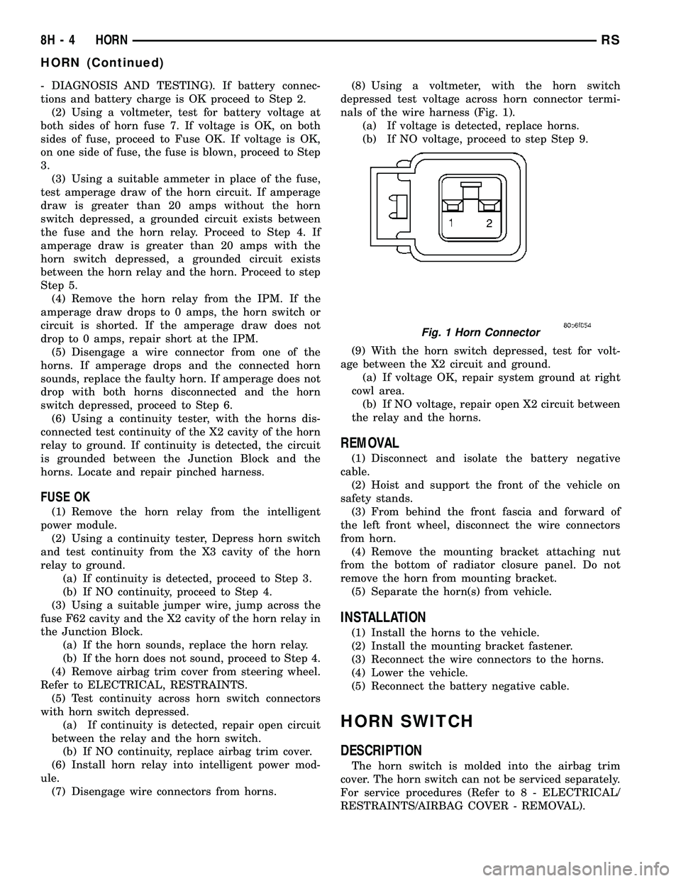
nals of the wire harness (Fig. 1).
(a) If voltage is detected, replace horns.
(b) If NO voltage, proceed to step Step 9.
(9) With the horn switch depressed, test for volt-
age between the X2 circuit and ground.
(a) If voltage OK, repair system ground at right
cowl area.
(b) If NO voltage, repair open X2 circuit between
the relay and the horns.
REMOVAL
(1) Disconnect and isolate the battery negative
cable.
(2) Hoist and support the front of the vehicle on
safety stands.
(3) From behind the front fascia and forward of
the left front wheel, disconnect the wire connectors
from horn.
(4) Remove the mounting bracket attaching nut
from the bottom of radiator closure panel. Do not
remove the horn from mounting bracket.
(5) Separate the horn(s) from vehicle.
INSTALLATION
(1) Install the horns to the vehicle.
(2) Install the mounting bracket fastener.
(3) Reconnect the wire connectors to the horns.
(4) Lower the vehicle.
(5) Reconnect the battery negative cable.
HORN SWITCH
DESCRIPTION
The horn switch is molded into the airbag trim
cover. The horn switch can not be serviced separately.
For service procedures (Refer to 8 - ELECTRICAL/
RESTRAINTS/AIRBAG COVER - REMOVAL).
Fig. 1 Horn Connector
8H - 4 HORNRS
HORN (Continued)
Page 364 of 2339

IGNITION CONTROL
TABLE OF CONTENTS
page page
IGNITION CONTROL
DESCRIPTION - IGNITION SYSTEM..........1
OPERATION - IGNITION SYSTEM...........1
SPECIFICATIONS
TORQUE.............................2
SPARK PLUG CABLE RESISTANCE........2
SPARK PLUG.........................2
FIRING ORDER........................3
AUTO SHUT DOWN RELAY
DESCRIPTION..........................3
OPERATION............................3
CAMSHAFT POSITION SENSOR
DESCRIPTION..........................4
OPERATION............................4
REMOVAL
REMOVAL - 2.4L.......................5
REMOVAL - 3.3/3.8L....................5
INSTALLATION
INSTALLATION - 2.4L...................6
INSTALLATION - 3.3/3.8L.................6
IGNITION COIL
DESCRIPTION..........................6
OPERATION............................6
REMOVAL
REMOVAL - 2.4L.......................7REMOVAL - 3.3/3.8L....................7
INSTALLATION
INSTALLATION - 2.4L...................7
INSTALLATION - 3.3/3.8L.................8
KNOCK SENSOR
DESCRIPTION..........................8
OPERATION............................8
REMOVAL
REMOVAL - 2.4L.......................8
REMOVAL - 3.8L.......................8
INSTALLATION
INSTALLATION - 2.4L...................8
INSTALLATION - 3.8L...................8
SPARK PLUG
DESCRIPTION
DESCRIPTION - STANDARD 4 CYLINDER . . . 9
DESCRIPTION - PLATINUM PLUGS........9
REMOVAL.............................10
INSTALLATION.........................10
SPARK PLUG CABLE
DESCRIPTION.........................10
REMOVAL - 2.0/2.4L.....................10
INSTALLATION - 2.0/2.4L.................10
IGNITION CONTROL
DESCRIPTION - IGNITION SYSTEM
NOTE: All engines use a fixed ignition timing sys-
tem. Basic ignition timing is not adjustable. All
spark advance is determined by the Powertrain
Control Module (PCM).
The ignition system used on these engines is
referred to as the Direct Ignition System (DIS). The
system's three main components are the coils, crank-
shaft position sensor, and camshaft position sensor. If
equipped with the coil on plug ignition system it uti-
lizes an ignition coil for every cylinder, it is mounted
directly over the each spark plug.
OPERATION - IGNITION SYSTEM
The crankshaft position sensor and camshaft posi-
tion sensor are hall effect devices. The camshaft posi-
tion sensor and crankshaft position sensor generate
pulses that are inputs to the PCM. The PCM deter-
mines engine position from these sensors. The PCM
calculates injector sequence and ignition timing from
crankshaft & camshaft position. For a description of
both sensors, refer to Camshaft Position Sensor and
Crankshaft Position Sensor.
RSIGNITION CONTROL8I-1
Page 366 of 2339
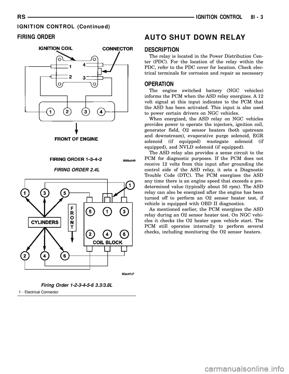
FIRING ORDERAUTO SHUT DOWN RELAY
DESCRIPTION
The relay is located in the Power Distribution Cen-
ter (PDC). For the location of the relay within the
PDC, refer to the PDC cover for location. Check elec-
trical terminals for corrosion and repair as necessary
OPERATION
The engine switched battery (NGC vehicles)
informs the PCM when the ASD relay energizes. A 12
volt signal at this input indicates to the PCM that
the ASD has been activated. This input is also used
to power certain drivers on NGC vehicles.
When energized, the ASD relay on NGC vehicles
provides power to operate the injectors, ignition coil,
generator field, O2 sensor heaters (both upstream
and downstream), evaporative purge solenoid, EGR
solenoid (if equipped) wastegate solenoid (if
equipped), and NVLD solenoid (if equipped).
The ASD relay also provides a sense circuit to the
PCM for diagnostic purposes. If the PCM does not
receive 12 volts from this input after grounding the
control side of the ASD relay, it sets a Diagnostic
Trouble Code (DTC). The PCM energizes the ASD
any time there is an engine speed that exceeds a pre-
determined value (typically about 50 rpm). The ASD
relay can also be energized after the engine has been
turned off to perform an O2 sensor heater test, if
vehicle is equipped with OBD II diagnostics.
As mentioned earlier, the PCM energizes the ASD
relay during an O2 sensor heater test. On NGC vehi-
cles it checks the O2 heater upon vehicle start. The
PCM still operates internally to perform several
checks, including monitoring the O2 sensor heaters.
FIRING ORDER 2.4L
Firing Order 1-2-3-4-5-6 3.3/3.8L
1 - Electrical Connector
RSIGNITION CONTROL8I-3
IGNITION CONTROL (Continued)
Page 368 of 2339

REMOVAL
REMOVAL - 2.4L
The camshaft position sensor is mounted to the
rear of the cylinder head.
(1) Remove the negative battery cable.
(2) Disconnect electrical connectors from the cam-
shaft position sensor (Fig. 3).
(3) Remove camshaft position sensor mounting
screws. Remove sensor.
(4) Loosen screw attaching target magnet to rear
of camshaft and remove magnet (Fig. 4).
REMOVAL - 3.3/3.8L
(1) Disconnect the negative battery cable.
(2) Remove the air box cover and inlet tube (Fig.
5).
(3) Disconnect camshaft position sensor electrical
connector from the wiring harness connector (Fig. 6).
(4) Remove bolt holding sensor.
(5) Rotate sensor away from block.
Fig. 3 EGR/CAM SENSOR 2.4L
Fig. 4 Target Magnet Removal/Installation
1 - TARGET MAGNET
2 - MOUNTING BOLT
3 - REAR OF CYLINDER HEAD
Fig. 5 AIR BOX COVER
Fig. 6 CAMSHAFT POSITION SENSOR
RSIGNITION CONTROL8I-5
CAMSHAFT POSITION SENSOR (Continued)
Page 371 of 2339
INSTALLATION - 3.3/3.8L
(1) Install coil over studs on bracket.
(2) Install 2 nuts to the ignition coil studs. Tighten
nuts and bolts.
(3) Connect the electrical connector to the ignition
coil.
(4) Install the ignition cables to the ignition coil.
(5) Reposition the Power steering reservoir. Slide
bracket over the mounting stud (Fig. 11).
(6) Install 2 bolts to the Power steering reservoir
to intake manifold.
(7) Tighten the lower nut to stud on ignition coil
bracket.
(8) Install the throttle and speed control cables to
clip.
(9) Connect the negative battery cable.
KNOCK SENSOR
DESCRIPTION
The knock sensor threads into the cylinder block.
The knock sensor is designed to detect engine vibra-
tion that is caused by detonation.
OPERATION
When the knock sensor detects a knock in one of
the cylinders, it sends an input signal to the PCM. In
response, the PCM retards ignition timing for all cyl-
inders by a scheduled amount.
Knock sensors contain a piezoelectric material
which constantly vibrates and sends an input voltage
(signal) to the PCM while the engine operates. As the
intensity of the crystal's vibration increases, the
knock sensor output voltage also increases.
The voltage signal produced by the knock sensor
increases with the amplitude of vibration. The PCM
receives as an input the knock sensor voltage signal.
If the signal rises above a predetermined level, the
PCM will store that value in memory and retard
ignition timing to reduce engine knock. If the knock
sensor voltage exceeds a preset value, the PCM
retards ignition timing for all cylinders. It is not a
selective cylinder retard.
The PCM ignores knock sensor input during engine
idle conditions. Once the engine speed exceeds a
specified value, knock retard is allowed.
Knock retard uses its own short term and long
term memory program.
Long term memory stores previous detonation
information in its battery-backed RAM. The maxi-
mum authority that long term memory has over tim-
ing retard can be calibrated.
Short term memory is allowed to retard timing up
to a preset amount under all operating conditions (as
long as rpm is above the minimum rpm) except WOT.The PCM, using short term memory, can respond
quickly to retard timing when engine knock is
detected. Short term memory is lost any time the
ignition key is turned off.
NOTE: Over or under tightening affects knock sen-
sor performance, possibly causing improper spark
control.
REMOVAL
REMOVAL - 2.4L
The knock sensor threads into the side of the cyl-
inder block in front of the starter (Fig. 12).
(1) Disconnect electrical connector from knock sen-
sor.
(2) Use a crow foot socket to remove the knock
sensors.
REMOVAL - 3.8L
The knock sensor threads into the side of the cyl-
inder block in the rear.
(1) Disconnect the negative battery cable.
(2) Raise vehicle and support.
(3) On All Wheel Drive vehicles remove the PTU
(Power Transfer Unit), refer to the Transmission sec-
tion for more information.
(4) Disconnect electrical connector from knock sen-
sor.
(5) Use a crow foot socket to remove the knock
sensor.
INSTALLATION
INSTALLATION - 2.4L
The knock sensor threads into the side of the cyl-
inder block in front of the starter (Fig. 12).
(1) Install knock sensor. Tighten knock sensor to
10 N´m (7 ft. lbs.) torque.Over or under tighten-
ing effects knock sensor performance, possibly
causing improper spark control.
(2) Attach electrical connector to knock sensor.
INSTALLATION - 3.8L
The knock sensor threads into the side of the cyl-
inder block in the rear.
(1) Install knock sensor. Tighten knock sensor to
10 N´m (7 ft. lbs.) torque.Over or under tighten-
ing effects knock sensor performance, possibly
causing improper spark control.
(2) Attach electrical connector to knock sensor.
(3) On All Wheel Drive vehicles install the PTU
(Power Transfer Unit) for the rear wheels, refer to
the Transmission section for more information.
8I - 8 IGNITION CONTROLRS
IGNITION COIL (Continued)