location CHRYSLER CARAVAN 2005 Service Manual
[x] Cancel search | Manufacturer: CHRYSLER, Model Year: 2005, Model line: CARAVAN, Model: CHRYSLER CARAVAN 2005Pages: 2339, PDF Size: 59.69 MB
Page 1362 of 2339
REMOVAL
The front cradle crossmember must be installed in
the design location to achieve proper front end sus-
pension alignment. If the cradle crossmember is
removed without applying reference marks on the
frame rails, align the cradle crossmember according
to the dimensions provided in this group.
NOTE: If the caged nuts in the frame rails become
damaged and cannot be reused, a replacement nut
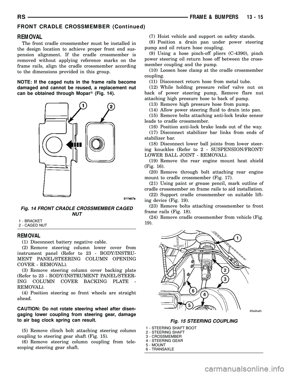
can be obtained through MoparT(Fig. 14).
REMOVAL
(1) Disconnect battery negative cable.
(2) Remove steering column lower cover from
instrument panel (Refer to 23 - BODY/INSTRU-
MENT PANEL/STEERING COLUMN OPENING
COVER - REMOVAL).
(3) Remove steering column cover backing plate
(Refer to 23 - BODY/INSTRUMENT PANEL/STEER-
ING COLUMN COVER BACKING PLATE -
REMOVAL).
(4) Position steering so front wheels are straight
ahead.
CAUTION: Do not rotate steering wheel after disen-
gaging lower coupling from steering gear, damage
to air bag clock spring can result.
(5) Remove clinch bolt attaching steering column
coupling to steering gear shaft (Fig. 15).
(6) Remove steering column coupling from tele-
scoping steering gear shaft.(7) Hoist vehicle and support on safety stands.
(8) Position a drain pan under power steering
pump and oil return hose coupling.
(9) Using a hose pinch-off pliers (C-4390), pinch
power steering oil return hose off between the cross-
member coupling and the pump.
(10) Loosen hose clamp at the cradle crossmember
coupling.
(11) Disconnect return hose from metal tube.
(12) While holding pressure relief valve nut on
back of power steering pump, Remove flare nut
attaching high pressure hose to back of pump.
(13) Remove high pressure hose from pump.
(14) Allow power steering fluid to drain into pan.
(15) Remove bolts attaching anti-lock brake sensor
leads to cradle crossmember.
(16) Position anti-lock brake leads out of the way.
(17) Disconnect stabilizer bar links from ends of
stabilizer bar.
(18) Disconnect lower ball joints from lower steer-
ing knuckles (Refer to 2 - SUSPENSION/FRONT/
LOWER BALL JOINT - REMOVAL).
(19) Remove the rear engine mount heat shield
(Fig. 16).
(20) Remove through bolt attaching rear engine
mount to cradle crossmember (Fig. 17).
(21) Using paint or grease pencil, mark outline of
cradle crossmember on frame rails to aid installation.
(22) Support cradle crossmember on suitable lift-
ing device (Fig. 19).
(23) Remove bolts attaching crossmember to front
frame rails (Fig. 18).
(24) Remove cradle crossmember from vehicle (Fig.
19).
Fig. 14 FRONT CRADLE CROSSMEMBER CAGED
NUT
1 - BRACKET
2 - CAGED NUT
Fig. 15 STEERING COUPLING
1 - STEERING SHAFT BOOT
2 - STEERING SHAFT
3 - CROSSMEMBER
4 - STEERING GEAR
5 - MOUNT
6 - TRANSAXLE
RSFRAME & BUMPERS13-15
FRONT CRADLE CROSSMEMBER (Continued)
Page 1367 of 2339
FUEL DELIVERY
DESCRIPTION
DESCRIPTION
The front wheel drive car uses a plastic fuel tank
located rear center of the vehicle.
The Fuel Delivery System consists of: the following
items:
²Electric fuel pump module
²Fuel filter
²Tubes/lines/hoses
²Fuel injectors
The in-tank fuel pump module contains the fuel
pump. The pump is serviced as part of the fuel pump
module. Refer to Fuel Pump Module.
The fuel filter is replaceable only as part of the
fuel pump module.
DESCRIPTION - FFV REPLACEMENT PARTS
Many components in a Flexible Fuel Vehicle (FFV)
are designed to be compatible with ethanol. Always
be sure that the vehicle is serviced with correct etha-
nol compatible parts.
CAUTION: Replacing fuel system components with
non-ethanol compatible components can damage
your vehicle and may void the warranty.
OPERATION
The fuel system provides fuel pressure by an
in-tank pump module. The Powertrain Control Mod-
ule (PCM) controls the operation of the fuel system
by providing battery voltage to the fuel pump
through the fuel pump relay. The PCM requires only
three inputs and a good ground to operate the fuel
pump relay. The three inputs are:
²Ignition voltage
²Crankshaft Position (CKP) sensor
²Camshaft Position (CMP) sensor
DIAGNOSIS AND TESTING - FUEL DELIVERY
SYSTEM
(Refer to Appropriate Diagnostic Information)
STANDARD PROCEDURE
STANDARD PROCEDURE - FUEL SYSTEM
PRESSURE RELEASE PROCEDURE
(1) Remove Fuel Pump relay from Power Distribu-
tion Center (PDC). For location of relay, refer to label
on underside of PDC cover.
(2) Start and run engine until it stalls.(3) Attempt restarting engine until it will no
longer run.
(4) Turn ignition key to OFF position.
(5) Return fuel pump relay to PDC.
(6) One or more Diagnostic Trouble Codes (DTC's)
may have been stored in PCM memory due to fuel
pump relay removal. The DRB IIItscan tool must be
used to erase a DTC.
STANDARD PROCEDURE - DRAINING FUEL
TANK
Two different procedures may be used to drain fuel
tank (lowering tank or using DRBIIItscan tool).
The quickest draining procedure involves lowering
the fuel tank.
WARNING: RELEASE FUEL SYSTEM PRESSURE
BEFORE SERVICING FUEL SYSTEM COMPONENTS.
SERVICE VEHICLES IN WELL VENTILATED AREAS
AND AVOID IGNITION SOURCES. NEVER SMOKE
WHILE SERVICING THE VEHICLE. THIS MAY
RESULT IN PERSONAL INJURY OR DEATH.
As an alternative procedure, the electric fuel pump
may be activated allowing tank to be drained at fuel
rail connection. Refer to DRBIIItscan tool for fuel
pump activation procedures. Before disconnecting
fuel line at fuel rail, release fuel pressure. Refer to
the Fuel System Pressure Release Procedure in this
group for procedures. Disconnect the fuel line at the
fuel rail and remove the plastic retainer from the
fuel rail. Take plastic retainer and install it back into
the fuel line from body. Check the O-ring and make
sure that it is in place and not damaged. Attach end
of special test hose tool number 6539 at fuel line con-
nection from the body line. Position opposite end of
this hose tool to an approved gasoline draining sta-
tion. Activate fuel pump and drain tank until empty.
When done remove the special test hose tool number
6539 from the body line. Remove the plastic retainer
from the special test hose tool number 6539 and rein-
stall it into the fuel line from the body. Check the
O-ring and make sure that it is in place and not
damaged. Install the fuel line to the fuel rail.
If electric fuel pump is not operating, tank must be
lowered for fuel draining. Refer to following proce-
dures.
(1) Remove fuel filler cap.
(2) Perform the Fuel System Pressure Release pro-
cedure.
(3) Disconnect negative cable from battery.
(4) Raise vehicle and support.
(5) Certain models are equipped with a separate
grounding wire (strap) connecting the fuel fill tube
assembly to the body. Disconnect wire by removing
screw.
14 - 2 FUEL DELIVERYRS
Page 1395 of 2339
The PCM uses crankshaft position reference to
determine injector sequence, ignition timing and the
presence of misfire. Once the PCM determines crank-
shaft position, it begins energizing the injectors in
sequence.
REMOVAL
(1) Disconnect the negative battery cable.
(2) Raise vehicle and support.
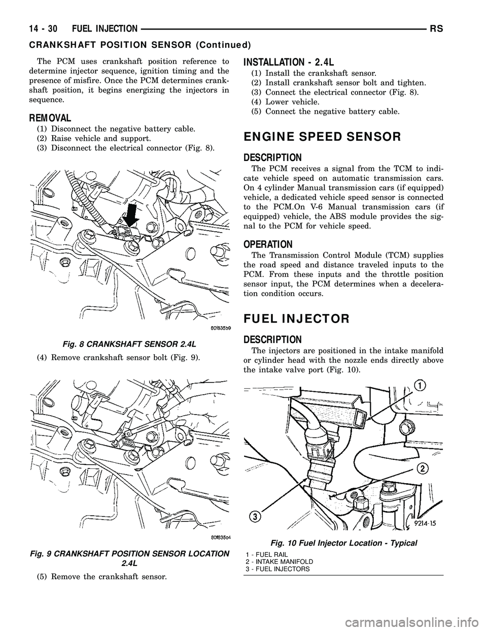
(3) Disconnect the electrical connector (Fig. 8).
(4) Remove crankshaft sensor bolt (Fig. 9).
(5) Remove the crankshaft sensor.
INSTALLATION - 2.4L
(1) Install the crankshaft sensor.
(2) Install crankshaft sensor bolt and tighten.
(3) Connect the electrical connector (Fig. 8).
(4) Lower vehicle.
(5) Connect the negative battery cable.
ENGINE SPEED SENSOR
DESCRIPTION
The PCM receives a signal from the TCM to indi-
cate vehicle speed on automatic transmission cars.
On 4 cylinder Manual transmission cars (if equipped)
vehicle, a dedicated vehicle speed sensor is connected
to the PCM.On V-6 Manual transmission cars (if
equipped) vehicle, the ABS module provides the sig-
nal to the PCM for vehicle speed.
OPERATION
The Transmission Control Module (TCM) supplies
the road speed and distance traveled inputs to the
PCM. From these inputs and the throttle position
sensor input, the PCM determines when a decelera-
tion condition occurs.
FUEL INJECTOR
DESCRIPTION
The injectors are positioned in the intake manifold
or cylinder head with the nozzle ends directly above
the intake valve port (Fig. 10).Fig. 8 CRANKSHAFT SENSOR 2.4L
Fig. 9 CRANKSHAFT POSITION SENSOR LOCATION
2.4L
Fig. 10 Fuel Injector Location - Typical
1 - FUEL RAIL
2 - INTAKE MANIFOLD
3 - FUEL INJECTORS
14 - 30 FUEL INJECTIONRS
CRANKSHAFT POSITION SENSOR (Continued)
Page 1397 of 2339
(5) Rotate injector and pull injector out of fuel rail.
The clip will stay on the injector.
(6) Check injector O-ring for damage. If O-ring is
damaged, it must be replaced. If injector is reused, a
protective cap must be installed on the injector tip to
prevent damage. Replace the injector clip if it is dam-
aged.
(7) Repeat for remaining injectors.
INSTALLATION
INSTALLATION - 2.4L
The fuel rail must be removed first. Refer to Fuel
Injector Rail Removal in this section.
(1) Before installing an injector the rubber O-ring
must be lubricated with a drop of clean engine oil to
aid in installation.
(2) Install injector clip by sliding open end into the
top slot of the injector. The edge of the receiver cup
will slide into the side slots of clip.
(3) Install injector top end into fuel rail receiver
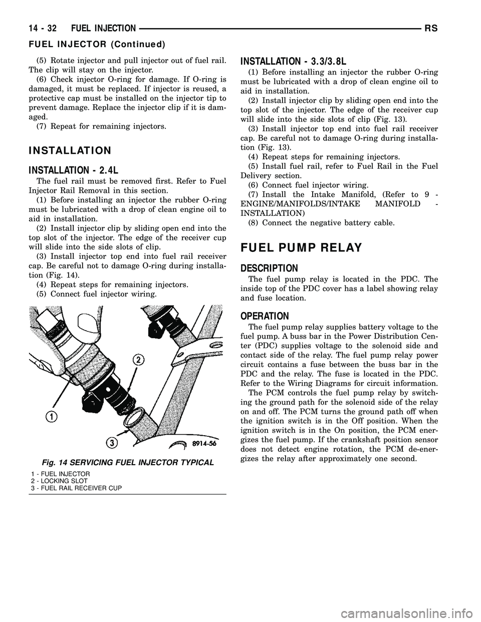
cap. Be careful not to damage O-ring during installa-
tion (Fig. 14).
(4) Repeat steps for remaining injectors.
(5) Connect fuel injector wiring.
INSTALLATION - 3.3/3.8L
(1) Before installing an injector the rubber O-ring
must be lubricated with a drop of clean engine oil to
aid in installation.
(2) Install injector clip by sliding open end into the
top slot of the injector. The edge of the receiver cup
will slide into the side slots of clip (Fig. 13).
(3) Install injector top end into fuel rail receiver
cap. Be careful not to damage O-ring during installa-
tion (Fig. 13).
(4) Repeat steps for remaining injectors.
(5) Install fuel rail, refer to Fuel Rail in the Fuel
Delivery section.
(6) Connect fuel injector wiring.
(7) Install the Intake Manifold, (Refer to 9 -
ENGINE/MANIFOLDS/INTAKE MANIFOLD -
INSTALLATION)
(8) Connect the negative battery cable.
FUEL PUMP RELAY
DESCRIPTION
The fuel pump relay is located in the PDC. The
inside top of the PDC cover has a label showing relay
and fuse location.
OPERATION
The fuel pump relay supplies battery voltage to the
fuel pump. A buss bar in the Power Distribution Cen-
ter (PDC) supplies voltage to the solenoid side and
contact side of the relay. The fuel pump relay power
circuit contains a fuse between the buss bar in the
PDC and the relay. The fuse is located in the PDC.
Refer to the Wiring Diagrams for circuit information.
The PCM controls the fuel pump relay by switch-
ing the ground path for the solenoid side of the relay
on and off. The PCM turns the ground path off when
the ignition switch is in the Off position. When the
ignition switch is in the On position, the PCM ener-
gizes the fuel pump. If the crankshaft position sensor
does not detect engine rotation, the PCM de-ener-
gizes the relay after approximately one second.
Fig. 14 SERVICING FUEL INJECTOR TYPICAL
1 - FUEL INJECTOR
2 - LOCKING SLOT
3 - FUEL RAIL RECEIVER CUP
14 - 32 FUEL INJECTIONRS
FUEL INJECTOR (Continued)
Page 1399 of 2339
(2) Install mounting screw. Tighten screw to 7 N´m
(62 in. lbs.) torque.
(3) Connect electrical connector to idle air control
motor.
(4) Connect negative cable to battery.
INLET AIR TEMPERATURE
SENSOR
DESCRIPTION
The IAT Sensor is a Negative Temperature Coeffi-
cient (NTC) Sensor that provides information to the
PCM regarding the temperature of the air entering
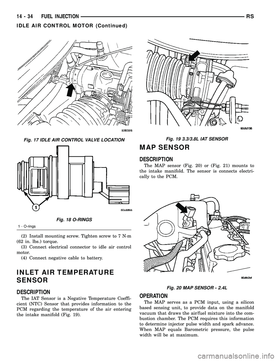
the intake manifold (Fig. 19).
MAP SENSOR
DESCRIPTION
The MAP sensor (Fig. 20) or (Fig. 21) mounts to
the intake manifold. The sensor is connects electri-
cally to the PCM.
OPERATION
The MAP serves as a PCM input, using a silicon
based sensing unit, to provide data on the manifold
vacuum that draws the air/fuel mixture into the com-
bustion chamber. The PCM requires this information
to determine injector pulse width and spark advance.
When MAP equals Barometric pressure, the pulse
width will be at maximum.
Fig. 17 IDLE AIR CONTROL VALVE LOCATION
Fig. 18 O-RINGS
1 - O-rings
Fig. 19 3.3/3.8L IAT SENSOR
Fig. 20 MAP SENSOR - 2.4L
14 - 34 FUEL INJECTIONRS
IDLE AIR CONTROL MOTOR (Continued)
Page 1404 of 2339
(2) Install sensor and tighten to 27 N´m (20 ft.
lbs.) (Fig. 23).
(3) Connect the electrical connector for the O2 sen-
sor and install onto bracket.
(4) Lower vehicle.
(5) Connect the negative battery cable.
INSTALLATION - UPSTREAM 1/1 - 3.3/3.8L
The engines uses two heated oxygen sensors.
(1) After removing the sensor, the exhaust mani-
fold threads must be cleaned with an 18 mm X 1.5 +
6E tap. If reusing the original sensor, coat the sensor
threads with an anti-seize compound such as Loctite
771- 64 or equivalent. New sensors have compound
on the threads and do not require an additional coat-
ing.
(2) Install sensor and tighten to 27 N´m (20 ft.
lbs.).
(3) Connect the electrical connector for the O2 sen-
sor and install onto bracket.
(4) Connect the electrical connector for the speed
control servo.
(5) Install the speed control servo and bracket
refer to the Speed Control Servo for more informa-
tion.
(6) Connect the speed control vacuum harness to
servo.
(7) Install the battery tray, refer to the Battery
section for more information.
(8) Install battery, refer to the Battery section for
more information.
INSTALLATION DOWNSTREAM 2/1 -
2.4/3.3/3.8L
The O2S is located on the side of the catalytic con-
verter.
Threads of new oxygen sensors are factory coated
with anti-seize compound to aid in removal.DO
NOT add any additional anti-seize compound to
the threads of a new oxygen sensor.
(1) Install sensor and tighten to 27 N´m (20 ft.
lbs.).
(2) Connect the electrical connector.
(3) Lower vehicle.
(4) Install the negative battery cable.
THROTTLE BODY
DESCRIPTION
The throttle body is located on the intake manifold
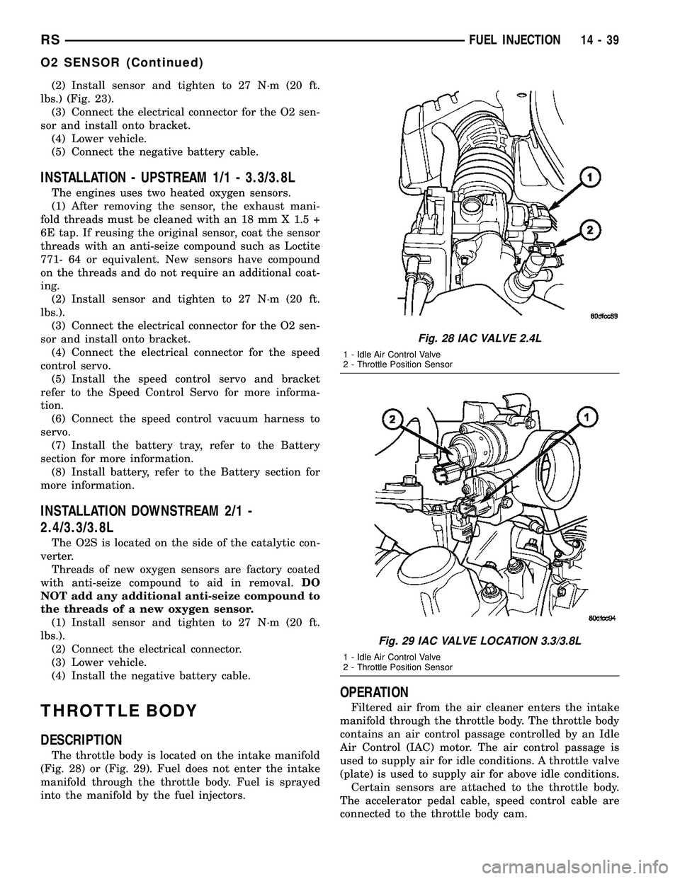
(Fig. 28) or (Fig. 29). Fuel does not enter the intake
manifold through the throttle body. Fuel is sprayed
into the manifold by the fuel injectors.
OPERATION
Filtered air from the air cleaner enters the intake
manifold through the throttle body. The throttle body
contains an air control passage controlled by an Idle
Air Control (IAC) motor. The air control passage is
used to supply air for idle conditions. A throttle valve
(plate) is used to supply air for above idle conditions.
Certain sensors are attached to the throttle body.
The accelerator pedal cable, speed control cable are
connected to the throttle body cam.
Fig. 28 IAC VALVE 2.4L
1 - Idle Air Control Valve
2 - Throttle Position Sensor
Fig. 29 IAC VALVE LOCATION 3.3/3.8L
1 - Idle Air Control Valve
2 - Throttle Position Sensor
RSFUEL INJECTION14-39
O2 SENSOR (Continued)
Page 1424 of 2339
(19) Position the lower shroud on the column (Fig.
8). Install the lower shroud mounting screw. Tighten
the screw to 2 N´m (17 in. lbs.) torque.
(20) If equipped with adjustable pedals, Connect
the wiring connector for the switch (Fig. 7) to the col-
umn wiring harness.
(21) Position the upper shroud on top of the lower
shroud and snap it into place. Install the upper
shroud mounting screws (Fig. 6). Tighten the screws
to 2 N´m (17 in. lbs.) torque.
(22) Inspect shroud mating surfaces for excessive
gaps and correct as necessary.
(23) Install the cluster trim bezel (Refer to 23 -
BODY/INSTRUMENT PANEL/CLUSTER BEZEL -
INSTALLATION).
(24) Install the knee blocker/steering column cover
plate. (Refer to 23 - BODY/INSTRUMENT PANEL/
KNEE BLOCKER - INSTALLATION)
(25) Install the parking brake handle link.
(26) Install the knee blocker/steering column open-
ing cover. (Refer to 23 - BODY/INSTRUMENT PAN-
EL/STEERING COLUMN OPENING COVER -
INSTALLATION)
(27) Align the splines and install the steering
wheel on the steering column shaft(Refer to 19 -
STEERING/COLUMN/STEERING WHEEL -
INSTALLATION).
(28) Install the damper over the steering column
shaft (Fig. 4).
(29) Install the steering wheel retaining bolt (Fig.
4). Tighten the bolt to 61 N´m (45 ft. lbs.) torque.
(30) If the steering wheel is equipped with remote
audio controls, connect the wiring connector to the
clockspring (Fig. 4).
(31) Connect the two squib connectors to the
driver airbag (Fig. 3). The connectors are color coded
to avoid connector mix-up.
(32) Connect the speed control and horn connector
to the clockspring (Fig. 3).
(33) Install the airbag to the steering wheel.
Install the driver airbag mounting screws (Fig. 2).
Tighten screws to 10 N´m (90 in. lbs.) torque.
(34) Connect the battery negative (ground) cable to
battery post following special Diagnosis And Testing
procedure. (Refer to 8 - ELECTRICAL/RESTRAINTS
- DIAGNOSIS AND TESTING)
(35) Check operation of all steering column
mounted components.
(36) Road test vehicle to ensure proper operation
of steering.SPECIFICATIONS
COLUMN FASTENER TORQUE
DESCRIPTION N´mFt.
Lbs.In.
Lbs.
Driver Airbag Mounting Screws 10 Ð 90
Multi-Function Switch Mounting
Housing Set-Screw14 Ð 124
Shroud Attaching Screws - Fixed 3 Ð 23
Shroud Attaching Screws -
Lower/Upper2Ð17
SKIM Attaching Screw 4 Ð 30
Steering Column Coupling Pinch
Bolt28 Ð 250
Steering Column Mounting Nuts 12 Ð 105
Steering Wheel Retaining Bolt 61 45 Ð
IGNITION SWITCH
REMOVAL
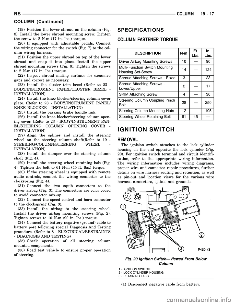
The ignition switch attaches to the lock cylinder
housing on the end opposite the lock cylinder (Fig.
20). For ignition switch terminal and circuit identifi-
cation, refer to the appropriate wiring information.
The wiring information includes wiring diagrams,
proper wire and connector repair procedures, further
details on wire harness routing and retention, as well
as pin-out and location views for the various wire
harness connectors, splices and grounds.
(1) Disconnect negative cable from battery.
Fig. 20 Ignition SwitchÐViewed From Below
Column
1 - IGNITION SWITCH
2 - LOCK CYLINDER HOUSING
3 - RETAINING TABS
RSCOLUMN19-17
COLUMN (Continued)
Page 1428 of 2339
SHROUD - LOWER
REMOVAL
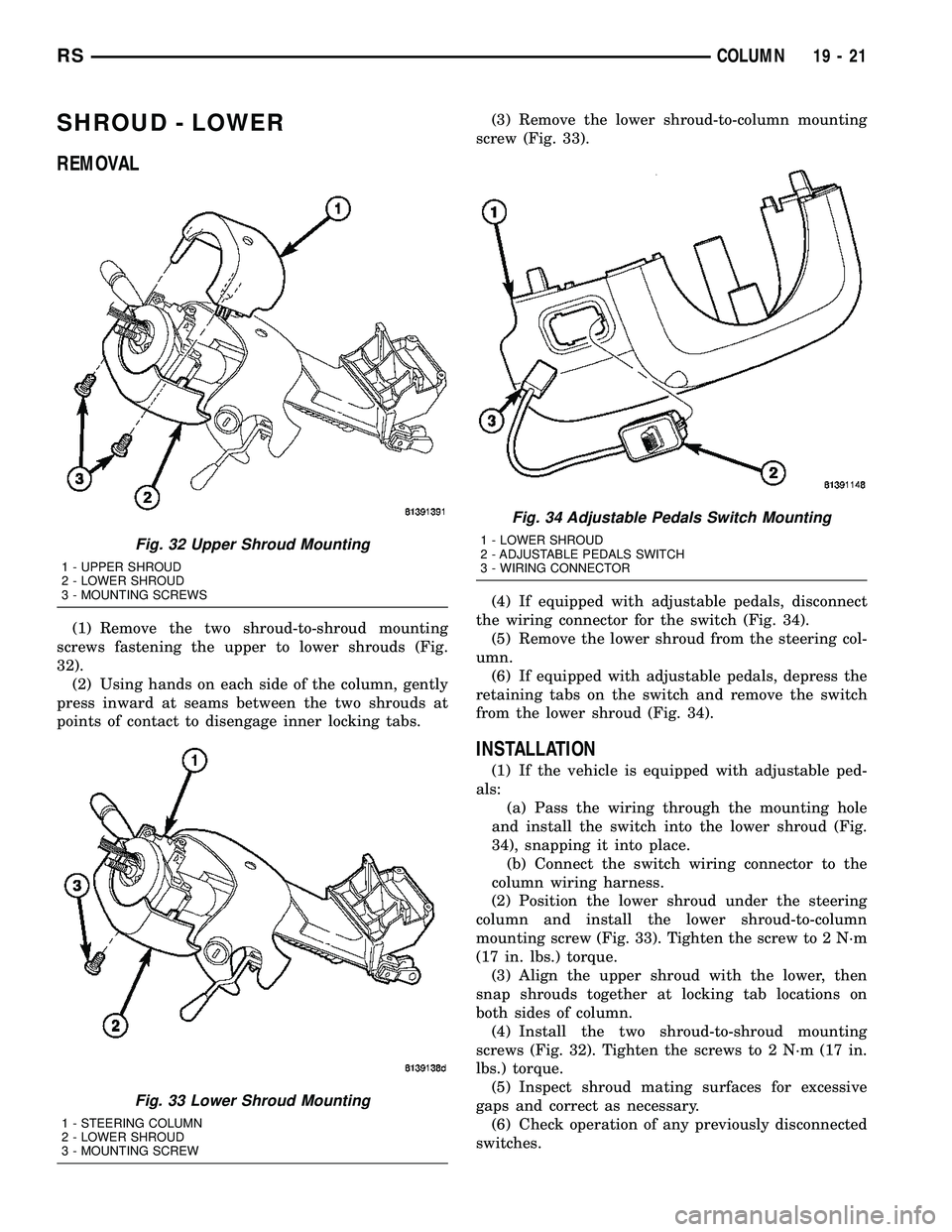
(1) Remove the two shroud-to-shroud mounting
screws fastening the upper to lower shrouds (Fig.
32).
(2) Using hands on each side of the column, gently
press inward at seams between the two shrouds at
points of contact to disengage inner locking tabs.(3) Remove the lower shroud-to-column mounting
screw (Fig. 33).
(4) If equipped with adjustable pedals, disconnect
the wiring connector for the switch (Fig. 34).
(5) Remove the lower shroud from the steering col-
umn.
(6) If equipped with adjustable pedals, depress the
retaining tabs on the switch and remove the switch
from the lower shroud (Fig. 34).
INSTALLATION
(1) If the vehicle is equipped with adjustable ped-
als:
(a) Pass the wiring through the mounting hole
and install the switch into the lower shroud (Fig.
34), snapping it into place.
(b) Connect the switch wiring connector to the
column wiring harness.
(2) Position the lower shroud under the steering
column and install the lower shroud-to-column
mounting screw (Fig. 33). Tighten the screw to 2 N´m
(17 in. lbs.) torque.
(3) Align the upper shroud with the lower, then
snap shrouds together at locking tab locations on
both sides of column.
(4) Install the two shroud-to-shroud mounting
screws (Fig. 32). Tighten the screws to 2 N´m (17 in.
lbs.) torque.
(5) Inspect shroud mating surfaces for excessive
gaps and correct as necessary.
(6) Check operation of any previously disconnected
switches.
Fig. 32 Upper Shroud Mounting
1 - UPPER SHROUD
2 - LOWER SHROUD
3 - MOUNTING SCREWS
Fig. 33 Lower Shroud Mounting
1 - STEERING COLUMN
2 - LOWER SHROUD
3 - MOUNTING SCREW
Fig. 34 Adjustable Pedals Switch Mounting
1 - LOWER SHROUD
2 - ADJUSTABLE PEDALS SWITCH
3 - WIRING CONNECTOR
RSCOLUMN19-21
Page 1430 of 2339
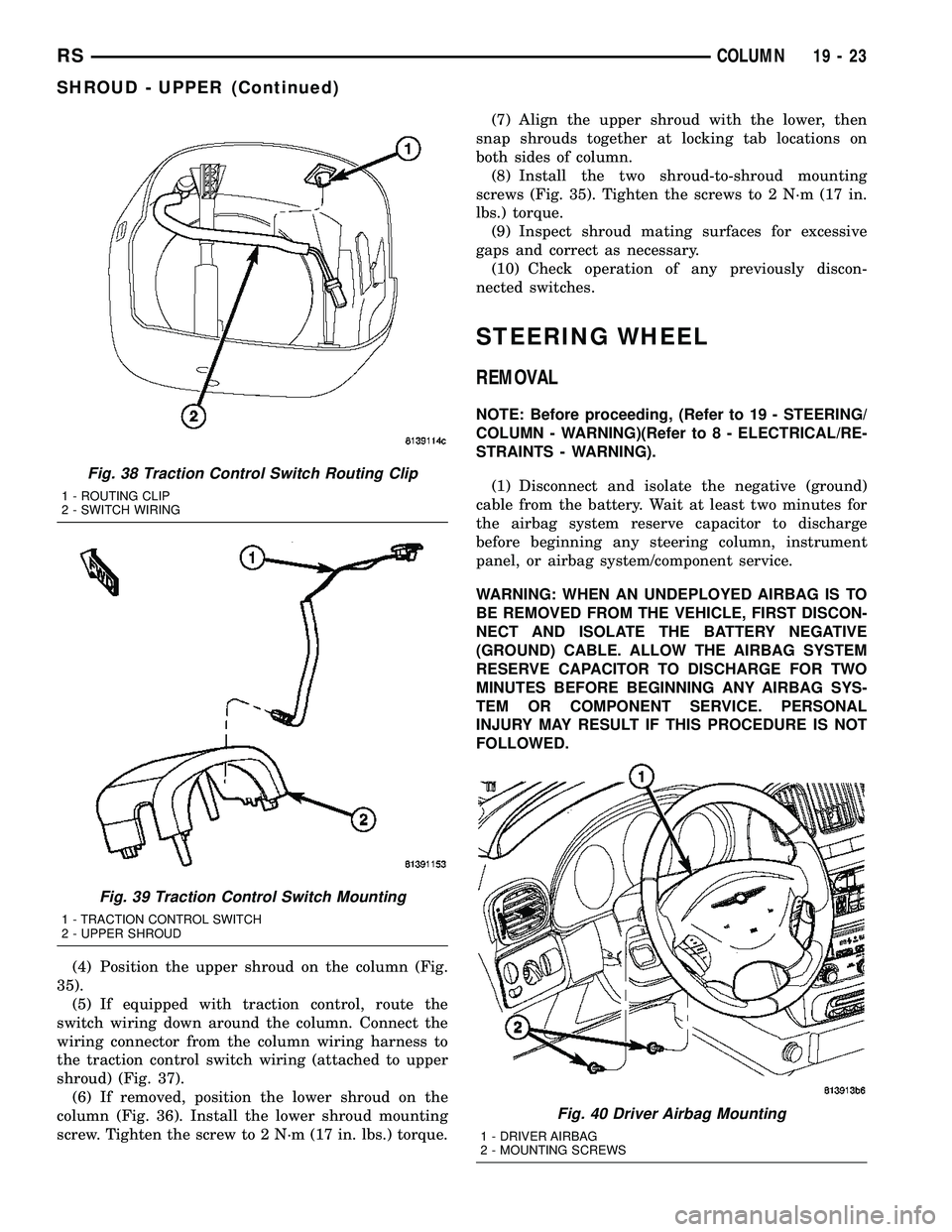
(4) Position the upper shroud on the column (Fig.
35).
(5) If equipped with traction control, route the
switch wiring down around the column. Connect the
wiring connector from the column wiring harness to
the traction control switch wiring (attached to upper
shroud) (Fig. 37).
(6) If removed, position the lower shroud on the
column (Fig. 36). Install the lower shroud mounting
screw. Tighten the screw to 2 N´m (17 in. lbs.) torque.(7) Align the upper shroud with the lower, then
snap shrouds together at locking tab locations on
both sides of column.
(8) Install the two shroud-to-shroud mounting
screws (Fig. 35). Tighten the screws to 2 N´m (17 in.
lbs.) torque.
(9) Inspect shroud mating surfaces for excessive
gaps and correct as necessary.
(10) Check operation of any previously discon-
nected switches.
STEERING WHEEL
REMOVAL
NOTE: Before proceeding, (Refer to 19 - STEERING/
COLUMN - WARNING)(Refer to 8 - ELECTRICAL/RE-
STRAINTS - WARNING).
(1) Disconnect and isolate the negative (ground)
cable from the battery. Wait at least two minutes for
the airbag system reserve capacitor to discharge
before beginning any steering column, instrument
panel, or airbag system/component service.
WARNING: WHEN AN UNDEPLOYED AIRBAG IS TO
BE REMOVED FROM THE VEHICLE, FIRST DISCON-
NECT AND ISOLATE THE BATTERY NEGATIVE
(GROUND) CABLE. ALLOW THE AIRBAG SYSTEM
RESERVE CAPACITOR TO DISCHARGE FOR TWO
MINUTES BEFORE BEGINNING ANY AIRBAG SYS-
TEM OR COMPONENT SERVICE. PERSONAL
INJURY MAY RESULT IF THIS PROCEDURE IS NOT
FOLLOWED.
Fig. 38 Traction Control Switch Routing Clip
1 - ROUTING CLIP
2 - SWITCH WIRING
Fig. 39 Traction Control Switch Mounting
1 - TRACTION CONTROL SWITCH
2 - UPPER SHROUD
Fig. 40 Driver Airbag Mounting
1 - DRIVER AIRBAG
2 - MOUNTING SCREWS
RSCOLUMN19-23
SHROUD - UPPER (Continued)
Page 1435 of 2339
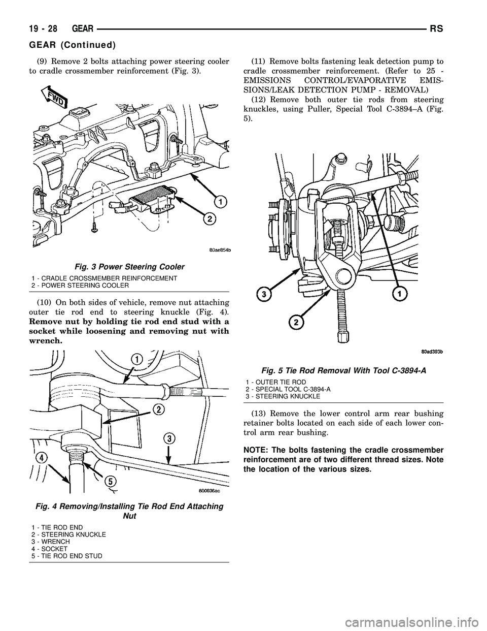
(9) Remove 2 bolts attaching power steering cooler
to cradle crossmember reinforcement (Fig. 3).
(10) On both sides of vehicle, remove nut attaching
outer tie rod end to steering knuckle (Fig. 4).
Remove nut by holding tie rod end stud with a
socket while loosening and removing nut with
wrench.(11) Remove bolts fastening leak detection pump to
cradle crossmember reinforcement. (Refer to 25 -
EMISSIONS CONTROL/EVAPORATIVE EMIS-
SIONS/LEAK DETECTION PUMP - REMOVAL)
(12) Remove both outer tie rods from steering
knuckles, using Puller, Special Tool C-3894±A (Fig.
5).
(13) Remove the lower control arm rear bushing
retainer bolts located on each side of each lower con-
trol arm rear bushing.
NOTE: The bolts fastening the cradle crossmember
reinforcement are of two different thread sizes. Note
the location of the various sizes.
Fig. 3 Power Steering Cooler
1 - CRADLE CROSSMEMBER REINFORCEMENT
2 - POWER STEERING COOLER
Fig. 4 Removing/Installing Tie Rod End Attaching
Nut
1 - TIE ROD END
2 - STEERING KNUCKLE
3 - WRENCH
4 - SOCKET
5 - TIE ROD END STUD
Fig. 5 Tie Rod Removal With Tool C-3894-A
1 - OUTER TIE ROD
2 - SPECIAL TOOL C-3894-A
3 - STEERING KNUCKLE
19 - 28 GEARRS
GEAR (Continued)