location CHRYSLER CARAVAN 2005 Service Manual
[x] Cancel search | Manufacturer: CHRYSLER, Model Year: 2005, Model line: CARAVAN, Model: CHRYSLER CARAVAN 2005Pages: 2339, PDF Size: 59.69 MB
Page 1297 of 2339

(1) Before installing the nuts the threads should
be oiled with engine oil.
(2) Install nuts finger tight on each bolt then alter-
nately torque each nut to assemble the cap properly.
(3) Tighten the nuts to 54 N´m PLUS 1/4 turn (40
ft. lbs. PLUS 1/4 turn).
(4) Using a feeler gauge, check connecting rod side
clearance (Fig. 53). Refer to Engine Specifications
(Refer to 9 - ENGINE - SPECIFICATIONS).
STANDARD PROCEDURE - FITTING PISTONS
The piston and cylinder wall must be clean and
dry. Piston diameter should be measured 90 degrees
to piston pin at size location shown in (Fig. 54). Cyl-
inder bores should be measured halfway down the
cylinder bore and transverse to the engine crankshaft
center line shown in (Fig. 55). Refer to Engine Spec-
ifications (Refer to 9 - ENGINE - SPECIFICA-
TIONS).Pistons and cylinder bores should be
measured at normal room temperature, 21ÉC
(70ÉF).
REMOVAL
(1) Disconnect negative cable from battery.
(2) Remove the cylinder heads. (Refer to 9 -
ENGINE/CYLINDER HEAD - REMOVAL)
(3) Remove the oil pan. (Refer to 9 - ENGINE/LU-
BRICATION/OIL PAN - REMOVAL)
(4) Remove the top ridge of cylinder bores with a
reliable ridge reamer, if necessary, before removing
pistons from cylinder block.Be sure to keep tops
of pistons covered during this operation. Pis-
tons and connecting rods must be removed
from top of cylinder block. When removing pis-
ton and connecting rod assemblies from the
engine, rotate crankshaft so that each connect-
ing rod is centered in cylinder bore.
(5) Inspect connecting rods and connecting rod
caps for cylinder identification. Identify them, if nec-
essary (Fig. 56).Fig. 53 Checking Connecting Rod Side Clearance
Fig. 54 Piston Measurement Locations - Typical
1 - 39.8 mm (1.56 in. ) 3.3L ENGINE
2 - 33.0 mm (1.29 in.) 3.8L ENGINE
Fig. 55 Checking Cylinder Bore Size
Fig. 56 Identify Connecting Rod to Cylinder
1 - CYLINDER NUMBER
9 - 120 ENGINE 3.3/3.8LRS
PISTON & CONNECTING ROD (Continued)
Page 1299 of 2339

Fig. 59 PISTON AND CONNECTING ROD INSTALLATION
1 - RING - OIL CONTROL 7 - CAP - CONNECTING ROD
2 - RING - NO. 2 COMPRESSION 8 - BEARING - CONNECTING ROD LOWER
3 - RING - NO. 1 COMPRESSION 9 - CRANKSHAFT JOURNAL PROTECTOR (RUBBER HOSE)
4 - RING - SIDE RAIL UPPER & LOWER 10 - BEARING - CONNECTING ROD UPPER
5 - PISTON RING COMPRESSOR 11 - PISTON AND CONNECTING ROD ASSEMBLY
6 - NUT - CONNECTING ROD 12 - PISTON LOCATION MARK (F = FRONT)
9 - 122 ENGINE 3.3/3.8LRS
PISTON & CONNECTING ROD (Continued)
Page 1305 of 2339

(6) Tighten number 1, 3 and 4 main cap bolts to 41
N´m + 1/4 Turn (30 ft. lbs.+ 1/4 Turn).
(7) Rotate the crankshaft until the number 6 pis-
ton is at TDC.
(8) To ensure correct thrust bearing alignment the
following procedure must be done:
a. Move crankshaft all the way to the rear of its
travel.
b. Then, move crankshaft all the way to the front
of its travel.
c. Wedge an appropriate tool between the rear of
the cylinder block and rear crankshaft counter-
weight. This will hold the crankshaft in it's most for-
ward position.
d. Tighten the #2 Thrust Bearing cap bolts to 41
N´m + 1/4 Turn (30 ft. lbs.+ 1/4 Turn). Remove the
holding tool.
(9) Install oil pan. (Refer to 9 - ENGINE/LUBRI-
CATION/OIL PAN - INSTALLATION)
(10) Fill engine crankcase with proper oil to cor-
rect level.
CRANKSHAFT
DESCRIPTION
DESCRIPTION - 3.3L
The nodular iron crankshaft is supported by four
main bearings, with number two position the thrust
bearing (Fig. 76). Crankshaft end sealing is provided
by front and rear rubber seals.
DESCRIPTION - 3.8L
The nodular iron crankshaft is supported by four
main bearings, with number two position providing
thrust bearing location (Fig. 77). Each main bearing
cap has two vertical retaining bolts. The two center
main caps have horizontal bolts to add increasedrigidity to the lower engine block (Fig. 77). Crank-
shaft end sealing is provided by front and rear rub-
ber seals.
STANDARD PROCEDURE - MEASURING
CRANKSHAFT END PLAY
(1) Mount a dial indicator to front of engine with
the locating probe on nose of crankshaft (Fig. 74).
(2) Move crankshaft all the way to the rear of its
travel.
(3) Zero the dial indicator.
(4) Move crankshaft all the way to the front and
read the dial indicator. (Refer to 9 - ENGINE -
SPECIFICATIONS) for end play specification.
REMOVAL
(1) Remove the engine assembly (Refer to 9 -
ENGINE - REMOVAL).
(2) Separate transaxle from engine.
(3) Mount engine on an engine stand.
(4) Remove the oil filter.
(5) Remove the oil pan and oil pick-up tube (Refer
to 9 - ENGINE/LUBRICATION/OIL PAN -
REMOVAL).
(6) Remove the timing chain cover (Refer to 9 -
ENGINE/VALVE TIMING/TIMING CHAIN COVER -
REMOVAL).
(7) Remove timing chain and sprockets (Refer to 9
- ENGINE/VALVE TIMING/TIMING CHAIN AND
SPROCKETS - REMOVAL).
(8) Remove crankshaft rear oil seal and retainer
(Refer to 9 - ENGINE/ENGINE BLOCK/CRANK-
SHAFT OIL SEAL - REAR - REMOVAL).
(9) Rotate the crankshaft until connecting rod cap
is accessible.
(10) Mark connecting rod cap position using a suit-
able marker/scribe tool.
Fig. 73 Check for Stretched (Necked) Bolts
1 - STRETCHED BOLT
2 - THREADS ARE NOT STRAIGHT ON LINE
3 - THREADS ARE STRAIGHT ON LINE
4 - UNSTRETCHED BOLT
Fig. 74 Checking Crankshaft End Play - Typical
9 - 128 ENGINE 3.3/3.8LRS
CRANKSHAFT MAIN BEARINGS (Continued)
Page 1316 of 2339

OIL
STANDARD PROCEDURE
STANDARD PROCEDURE - ENGINE OIL AND
FILTER CHANGE
Change engine oil at mileage and time intervals
described in the Maintenance Schedule. (Refer to
LUBRICATION & MAINTENANCE/MAINTE-
NANCE SCHEDULES - DESCRIPTION)
WARNING: NEW OR USED ENGINE OIL CAN BE
IRRITATING TO THE SKIN. AVOID PROLONGED OR
REPEATED SKIN CONTACT WITH ENGINE OIL.
CONTAMINANTS IN USED ENGINE OIL, CAUSED BY
INTERNAL COMBUSTION, CAN BE HAZARDOUS TO
YOUR HEALTH. THOROUGHLY WASH EXPOSED
SKIN WITH SOAP AND WATER. DO NOT WASH
SKIN WITH GASOLINE, DIESEL FUEL, THINNER, OR
SOLVENTS, HEALTH PROBLEMS CAN RESULT. DO
NOT POLLUTE, DISPOSE OF USED ENGINE OIL
PROPERLY. CONTACT YOUR DEALER OR GOVERN-
MENT AGENCY FOR LOCATION OF COLLECTION
CENTER IN YOUR AREA.Run engine until achieving normal operating tem-
perature.
(1) Position the vehicle on a level surface and turn
engine off.
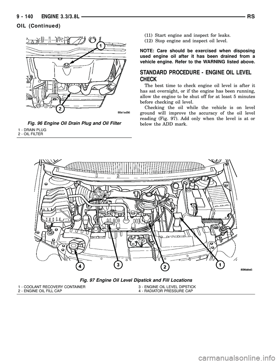
(2) Open hood, remove oil fill cap (Fig. 97).
(3) Hoist and support vehicle on safety stands.
Refer to Hoisting and Jacking Recommendations.
(Refer to LUBRICATION & MAINTENANCE/HOIST-
ING - STANDARD PROCEDURE)
(4) Place a suitable drain pan under crankcase
drain (Fig. 96).
(5) Remove drain plug from crankcase (Fig. 96)
and allow oil to drain into pan. Inspect drain plug
threads for stretching or other damage. Replace
drain plug and gasket if damaged.
(6) Remove oil filter. (Refer to 9 - ENGINE/LUBRI-
CATION/OIL FILTER - REMOVAL)
(7) Install and tighten drain plug in crankcase.
(8) Install new oil filter. (Refer to 9 - ENGINE/LU-
BRICATION/OIL FILTER - INSTALLATION)
(9) Lower vehicle and fill crankcase with specified
type and amount of engine oil. (Refer to LUBRICA-
TION & MAINTENANCE/FLUID TYPES -
DESCRIPTION)
(10) Install oil fill cap.
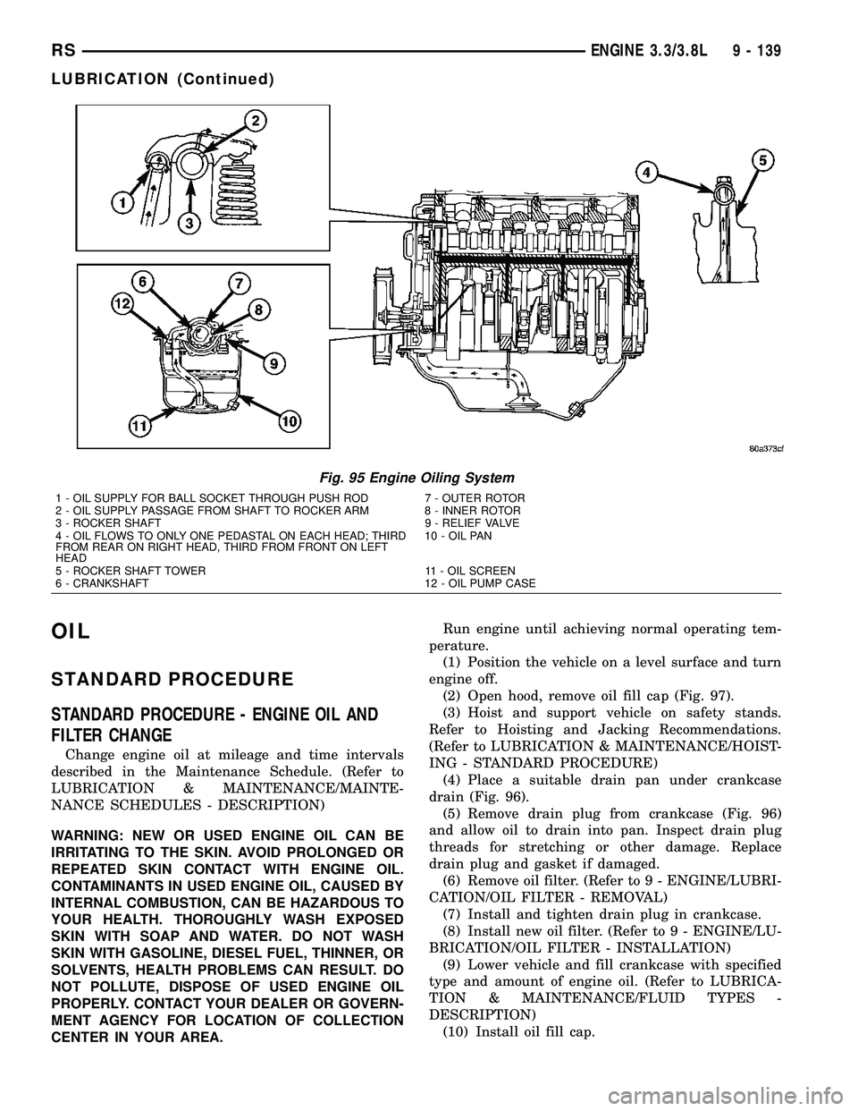
Fig. 95 Engine Oiling System
1 - OIL SUPPLY FOR BALL SOCKET THROUGH PUSH ROD 7 - OUTER ROTOR
2 - OIL SUPPLY PASSAGE FROM SHAFT TO ROCKER ARM 8 - INNER ROTOR
3 - ROCKER SHAFT 9 - RELIEF VALVE
4 - OIL FLOWS TO ONLY ONE PEDASTAL ON EACH HEAD; THIRD
FROM REAR ON RIGHT HEAD, THIRD FROM FRONT ON LEFT
HEAD10 - OIL PAN
5 - ROCKER SHAFT TOWER 11 - OIL SCREEN
6 - CRANKSHAFT 12 - OIL PUMP CASE
RSENGINE 3.3/3.8L9 - 139
LUBRICATION (Continued)
Page 1317 of 2339

(11) Start engine and inspect for leaks.
(12) Stop engine and inspect oil level.
NOTE: Care should be exercised when disposing
used engine oil after it has been drained from a
vehicle engine. Refer to the WARNING listed above.
STANDARD PROCEDURE - ENGINE OIL LEVEL
CHECK
The best time to check engine oil level is after it
has sat overnight, or if the engine has been running,
allow the engine to be shut off for at least 5 minutes
before checking oil level.
Checking the oil while the vehicle is on level
ground will improve the accuracy of the oil level
reading (Fig. 97). Add only when the level is at or
below the ADD mark.
Fig. 97 Engine Oil Level Dipstick and Fill Locations
1 - COOLANT RECOVERY CONTAINER 3 - ENGINE OIL LEVEL DIPSTICK
2 - ENGINE OIL FILL CAP 4 - RADIATOR PRESSURE CAP
Fig. 96 Engine Oil Drain Plug and Oil Filter
1 - DRAIN PLUG
2 - OIL FILTER
9 - 140 ENGINE 3.3/3.8LRS
OIL (Continued)
Page 1320 of 2339

INSPECTION
(1) Inspect oil drain plug and plug hole for
stripped or damaged threads and repair as necessary.
Install a new drain plug gasket. Tighten to 27 N´m
(20 ft. lbs.).
(2) Inspect oil pan mounting flange for bends or
distortion. Straighten flange if necessary.
(3) Inspect condition of oil screen and pick-up tube.
INSTALLATION
(1) Clean sealing surfaces and apply a 1/8 inch
bead of MopartEngine RTV GEN II at the parting
line of the chain case cover and the rear seal retainer
(Fig. 103).
(2) Position a new pan gasket on oil pan (Fig. 102).
(3) Install oil pan and tighten fasteners to 12 N´m
(105 in. lbs.) (Fig. 102).
(4) Install cover to transaxle case (Fig. 101).
(5) Install the strut bolt to transaxle housing (Fig.
101). Tighten all bending brace bolts.
(6) Install the drive belt splash shield.
(7) Lower vehicle and install oil dipstick.
(8) Connect negative cable to battery.
(9) Fill crankcase with oil to proper level.
OIL PRESSURE RELIEF VALVE
REMOVAL
(1) Remove oil pan (Refer to 9 - ENGINE/LUBRI-
CATION/OIL PAN - REMOVAL).
(2) Drill a 3.175 mm (1/8 in.) hole in the center of
the retainer cap (Fig. 104). Insert a self-threading
sheet metal screw into the cap.
(3) Using suitable pliers, remove cap and discard.
(4) Remove spring and relief valve (Fig. 104).
Fig. 102 OIL PAN
1 - GASKET
2 - BOLT
3 - OIL PAN
4 - NUT
Fig. 103 Oil Pan Sealing
1 - SEALER LOCATIONS
Fig. 104 Oil Pressure Relief Valve
1 - RELIEF VALVE
2 - SPRING
3 - RETAINER CAP
RSENGINE 3.3/3.8L9 - 143
OIL PAN (Continued)
Page 1329 of 2339

(9) Install the upper intake manifold. (Refer to 9 -
ENGINE/MANIFOLDS/INTAKE MANIFOLD -
INSTALLATION)
(10) Connect negative battery cable.(11) Fill the cooling system. (Refer to 7 - COOL-
ING - STANDARD PROCEDURE)
EXHAUST MANIFOLD - RIGHT
REMOVAL
(1) Disconnect battery negative cable.
(2) Remove the wiper module. (Refer to 8 - ELEC-
TRICAL/WIPERS/WASHERS/WIPER MODULE -
REMOVAL)
(3) Disconnect spark plug wires.
(4) Remove bolts fastening crossover pipe to
exhaust manifold (Fig. 125).
(5) Disconnect and remove the upstream oxygen
sensor (Fig. 128).
Fig. 122 INTAKE MANIFOLD - LOWER
1 - INTAKE MANIFOLD - LOWER
2 - BOLT - GASKET END SEAL RETAINER
3 - GASKET
4 - BOLT - LOWER INTAKE MANIFOLD
Fig. 123 Intake Manifold Gasket Sealing
1 - SEALER LOCATIONS
Fig. 124 LOWER MANIFOLD TIGHTENING
SEQUENCE
Fig. 125 CROSS-OVER PIPE
1 - CROSS-OVER PIPE
2 - BOLT
3 - GASKET
4 - FLAG NUT
9 - 152 ENGINE 3.3/3.8LRS
INTAKE MANIFOLD - LOWER (Continued)
Page 1335 of 2339

(9) Install crankshaft vibration damper. (Refer to 9
- ENGINE/ENGINE BLOCK/VIBRATION DAMPER -
INSTALLATION)
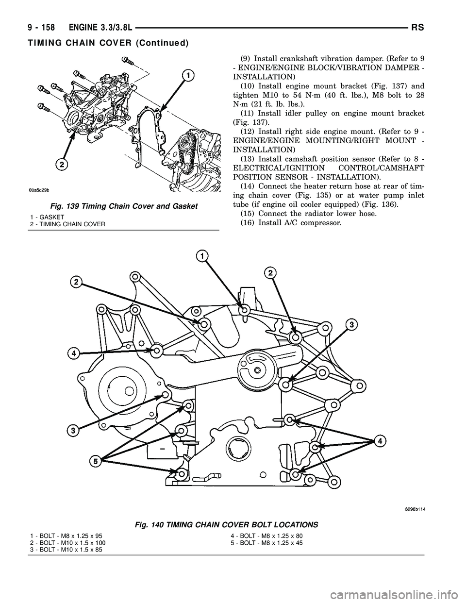
(10) Install engine mount bracket (Fig. 137) and
tighten M10 to 54 N´m (40 ft. lbs.), M8 bolt to 28
N´m (21 ft. lb. lbs.).
(11) Install idler pulley on engine mount bracket
(Fig. 137).
(12) Install right side engine mount. (Refer to 9 -
ENGINE/ENGINE MOUNTING/RIGHT MOUNT -
INSTALLATION)
(13) Install camshaft position sensor (Refer to 8 -
ELECTRICAL/IGNITION CONTROL/CAMSHAFT
POSITION SENSOR - INSTALLATION).
(14) Connect the heater return hose at rear of tim-
ing chain cover (Fig. 135) or at water pump inlet
tube (if engine oil cooler equipped) (Fig. 136).
(15) Connect the radiator lower hose.
(16) Install A/C compressor.
Fig. 139 Timing Chain Cover and Gasket
1 - GASKET
2 - TIMING CHAIN COVER
Fig. 140 TIMING CHAIN COVER BOLT LOCATIONS
1 - BOLT - M8 x 1.25 x 95 4 - BOLT - M8 x 1.25 x 80
2 - BOLT - M10 x 1.5 x 100 5 - BOLT - M8 x 1.25 x 45
3 - BOLT - M10 x 1.5 x 85
9 - 158 ENGINE 3.3/3.8LRS
TIMING CHAIN COVER (Continued)
Page 1353 of 2339

(3) Align and insert the center forward tab.
(4) Align the remaining tabs and press into the
slots, starting in the center and working outboard.
(5) Assure all tabs are fully engaged into the fas-
cia.
(6) If rear bumper fascia has been removed install.
(Refer to 13 - FRAME & BUMPERS/BUMPERS/
REAR FASCIA - INSTALLATION).
FRAME
SPECIFICATIONS
SPECIFICATIONS - FRAME DIMENSIONS
Frame dimensions are listed in metric scale. All
dimensions are from center to center of PrincipalLocating Point (PLP), or from center to center of PLP
and fastener location.
VEHICLE PREPARATION
Position the vehicle on a frame alignment rack,
refer to instructions provided with equipment being
used. Adjust the vehicle PLP heights to the specified
dimension above the work surface (datum line). Ver-
tical dimensions can be taken from the datum line to
the locations indicated were applicable.
INDEX
DESCRIPTION FIGURE
CROSSMEMBER DIMENSIONS 8
ENGINE BOX - TOP VIEW 9
ENGINE COMPARTMENT AND FRAME RAIL - SIDE VIEW 10
FULL VEHICLE - BOTTOM VIEW 11
13 - 6 FRAME & BUMPERSRS
REAR FASCIA - SCUFF PAD (Continued)
Page 1361 of 2339

SPECIFICATIONS - TORQUE
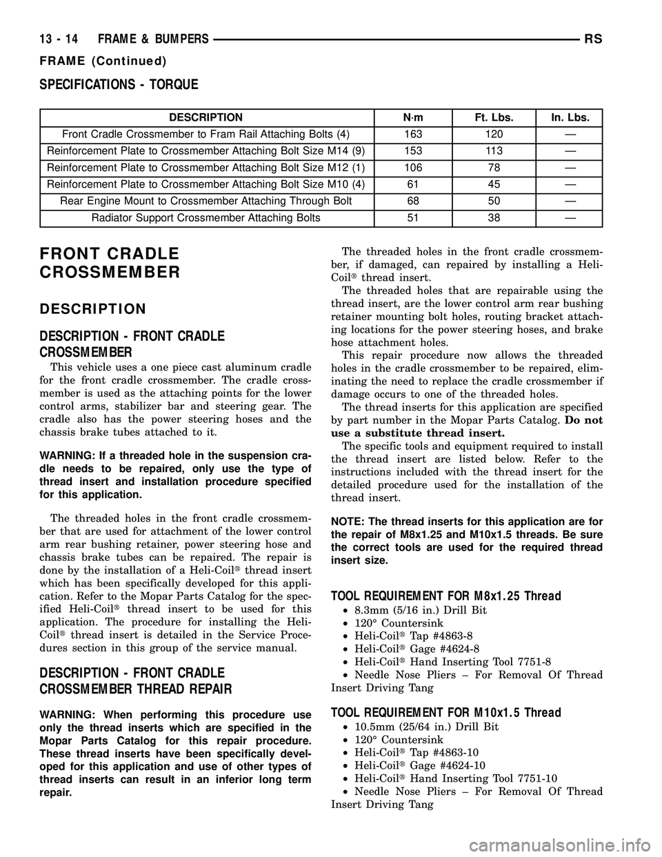
DESCRIPTION N´m Ft. Lbs. In. Lbs.
Front Cradle Crossmember to Fram Rail Attaching Bolts (4) 163 120 Ð
Reinforcement Plate to Crossmember Attaching Bolt Size M14 (9) 153 113 Ð
Reinforcement Plate to Crossmember Attaching Bolt Size M12 (1) 106 78 Ð
Reinforcement Plate to Crossmember Attaching Bolt Size M10 (4) 61 45 Ð
Rear Engine Mount to Crossmember Attaching Through Bolt 68 50 Ð
Radiator Support Crossmember Attaching Bolts 51 38 Ð
FRONT CRADLE
CROSSMEMBER
DESCRIPTION
DESCRIPTION - FRONT CRADLE
CROSSMEMBER
This vehicle uses a one piece cast aluminum cradle
for the front cradle crossmember. The cradle cross-
member is used as the attaching points for the lower
control arms, stabilizer bar and steering gear. The
cradle also has the power steering hoses and the
chassis brake tubes attached to it.
WARNING: If a threaded hole in the suspension cra-
dle needs to be repaired, only use the type of
thread insert and installation procedure specified
for this application.
The threaded holes in the front cradle crossmem-
ber that are used for attachment of the lower control
arm rear bushing retainer, power steering hose and
chassis brake tubes can be repaired. The repair is
done by the installation of a Heli-Coiltthread insert
which has been specifically developed for this appli-
cation. Refer to the Mopar Parts Catalog for the spec-
ified Heli-Coiltthread insert to be used for this
application. The procedure for installing the Heli-
Coiltthread insert is detailed in the Service Proce-
dures section in this group of the service manual.
DESCRIPTION - FRONT CRADLE
CROSSMEMBER THREAD REPAIR
WARNING: When performing this procedure use
only the thread inserts which are specified in the
Mopar Parts Catalog for this repair procedure.
These thread inserts have been specifically devel-
oped for this application and use of other types of
thread inserts can result in an inferior long term
repair.The threaded holes in the front cradle crossmem-
ber, if damaged, can repaired by installing a Heli-
Coiltthread insert.
The threaded holes that are repairable using the
thread insert, are the lower control arm rear bushing
retainer mounting bolt holes, routing bracket attach-
ing locations for the power steering hoses, and brake
hose attachment holes.
This repair procedure now allows the threaded
holes in the cradle crossmember to be repaired, elim-
inating the need to replace the cradle crossmember if
damage occurs to one of the threaded holes.
The thread inserts for this application are specified
by part number in the Mopar Parts Catalog.Do not
use a substitute thread insert.
The specific tools and equipment required to install
the thread insert are listed below. Refer to the
instructions included with the thread insert for the
detailed procedure used for the installation of the
thread insert.
NOTE: The thread inserts for this application are for
the repair of M8x1.25 and M10x1.5 threads. Be sure
the correct tools are used for the required thread
insert size.
TOOL REQUIREMENT FOR M8x1.25 Thread
²8.3mm (5/16 in.) Drill Bit
²120É Countersink
²Heli-CoiltTap #4863-8
²Heli-CoiltGage #4624-8
²Heli-CoiltHand Inserting Tool 7751-8
²Needle Nose Pliers ± For Removal Of Thread
Insert Driving Tang
TOOL REQUIREMENT FOR M10x1.5 Thread
²10.5mm (25/64 in.) Drill Bit
²120É Countersink
²Heli-CoiltTap #4863-10
²Heli-CoiltGage #4624-10
²Heli-CoiltHand Inserting Tool 7751-10
²Needle Nose Pliers ± For Removal Of Thread
Insert Driving Tang
13 - 14 FRAME & BUMPERSRS
FRAME (Continued)