location CHRYSLER CARAVAN 2005 Service Manual
[x] Cancel search | Manufacturer: CHRYSLER, Model Year: 2005, Model line: CARAVAN, Model: CHRYSLER CARAVAN 2005Pages: 2339, PDF Size: 59.69 MB
Page 1172 of 2339

Fig. 49 LIFTGATE
RS8W-91 CONNECTOR/GROUND/SPLICE LOCATION8W-91-59
CONNECTOR/GROUND/SPLICE LOCATION (Continued)
Page 1173 of 2339

Fig. 50 HEADLINER
8W - 91 - 60 8W-91 CONNECTOR/GROUND/SPLICE LOCATIONRS
CONNECTOR/GROUND/SPLICE LOCATION (Continued)
Page 1176 of 2339
(5) Connect the negative and positive battery
cables.
(6) Using a scan tool, check for any stored diagnos-
tic trouble codes. Ensure that all vehicle options are
operational.
IOD FUSE
DESCRIPTION
All vehicles are equipped with an Ignition-Off
Draw (IOD) fuse that is removed from its normal
cavity in the Integrated Power Module (IPM) when
the vehicle is shipped from the factory. Dealer per-
sonnel are to remove the IOD fuse from the storage
location and install it into the IPM fuse cavity
marked IOD as part of the preparation procedures
performed just prior to new vehicle delivery.
The IOD fuse is a 20 ampere blade-type mini fuse
and, when removed, it is stored in a fuse cavity adja-
cent to the washer fuse within the IPM.
OPERATION
The term ignition-off draw (IOD) identifies a nor-
mal condition where power is being drained from the
battery with the ignition switch in the Off position.
The IOD fuse feeds the memory and sleep mode func-
tions for some of the electronic modules in the vehicle
as well as various other accessories that require bat-
tery current when the ignition switch is in the Off
position, including the clock. The only reason the
IOD fuse is removed is to reduce the normal IOD of
the vehicle electrical system during new vehicle
transportation and pre-delivery storage to reduce
battery depletion, while still allowing vehicle opera-
tion so that the vehicle can be loaded, unloaded and
moved as needed by both vehicle transportation com-
pany and dealer personnel.
The IOD fuse is removed from the Integrated
Power Module (IPM) fuse cavity when the vehicle is
shipped from the assembly plant. Dealer personnel
must install the IOD fuse when the vehicle is being
prepared for delivery in order to restore full electrical
system operation. Once the vehicle is prepared for
delivery, the IOD function of this fuse becomes trans-
parent and the fuse that has been assigned the IOD
designation becomes only another Fused B(+) circuit
fuse. The IOD fuse serves no useful purpose to the
dealer technician in the service or diagnosis of any
vehicle system or condition, other than the same pur-
pose as that of any other standard circuit protection
device.
The IOD fuse can be used by the vehicle owner as
a convenient means of reducing battery depletion
when a vehicle is to be stored for periods not to
exceed approximately thirty days. However, it mustbe remembered that removing the IOD fuse will not
eliminate IOD, but only reduce this normal condition.
If a vehicle will be stored for more than thirty days,
the battery negative cable should be disconnected to
eliminate normal IOD; and, the battery should be
tested and recharged at regular intervals during the
vehicle storage period to prevent the battery from
becoming discharged or damaged.
POWER OUTLET
DESCRIPTION
Two power outlets are installed in the instrument
panel center lower bezel. Two additional power out-
lets are incorporated into the left rear C-pillar and
the center console (if equipped). The power outlets
bases are secured by a snap fit. A hinged plug flips
closed to conceal and protect the power outlet base
when not in use.
OPERATION
The power outlet base or receptacle shell is con-
nected to ground, and an insulated contact in the
bottom of the shell is connected to battery current.
The power outlet on the instrument panel marked
with a battery receives battery voltage from a fuse in
the Integrated Power Module (IPM) at all times. The
other power outlet on the instrument panel marked
with a key receives battery voltage only when the
key is in the on position.
The power outlet located in the center console
receives battery voltage all the time when positioned
between thefront seatsand key-on voltage when
positioned between therear seats. The power outlet
located on the C-pillar receives battery voltage only
when the key is in the ON position.
DIAGNOSIS AND TESTING
DIAGNOSIS & TESTING - POWER OUTLET
WARNING: ON VEHICLES EQUIPPED WITH AIR-
BAGS, REFER TO RESTRAINTS BEFORE ATTEMPT-
ING ANY STEERING WHEEL, STEERING COLUMN,
SEAT OR INSTRUMENT PANEL COMPONENT DIAG-
NOSIS OR SERVICE. FAILURE TO TAKE THE
PROPER PRECAUTIONS COULD RESULT IN ACCI-
DENTAL AIRBAG DEPLOYMENT AND POSSIBLE
PERSONAL INJURY.
(1) Check the fused B(+) fuse in the Integrated
Power Module (IPM). If OK, go to Step 2. If not OK,
repair the shorted circuit or component as required
and replace the faulty fuse.
RS8W-97 POWER DISTRIBUTION SYSTEM8W-97-3
INTEGRATED POWER MODULE (Continued)
Page 1180 of 2339
REMOVAL - CAMSHAFT SPROCKETS.....66
REMOVAL - CRANKSHAFT SPROCKET....66
CLEANING............................67
INSTALLATION
INSTALLATION - CRANKSHAFT SPROCKET . 67
INSTALLATION - CAMSHAFT SPROCKETS . . 67
INSTALLATION - TIMING BELT...........67
TIMING BELT TENSIONER & PULLEY
REMOVAL.............................69INSTALLATION.........................70
BALANCE SHAFTS AND CARRIER ASSEMBLY
DESCRIPTION.........................71
OPERATION...........................71
REMOVAL.............................71
INSTALLATION.........................73
ENGINE 2.4L
DESCRIPTION
The 2.4 Liter (148 cu. in.) in-line four cylinder
engine is a double over head camshaft with hydraulic
lash adjusters and four valve per cylinder design.
The engine is free-wheeling; meaning it has provi-
sions for piston-to-valve clearance. However valve-to-
valve interference can occur, if camshafts are rotated
independently.
The cylinders are numbered from front of the
engine to the rear. The firing order is 1±3±4±2.
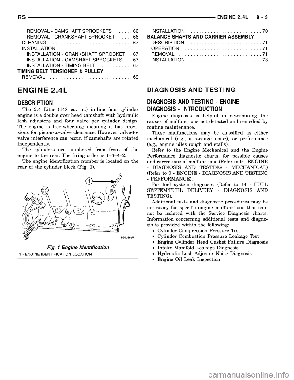
The engine identification number is located on the
rear of the cylinder block (Fig. 1).
DIAGNOSIS AND TESTING
DIAGNOSIS AND TESTING - ENGINE
DIAGNOSIS - INTRODUCTION
Engine diagnosis is helpful in determining the
causes of malfunctions not detected and remedied by
routine maintenance.
These malfunctions may be classified as either
mechanical (e.g., a strange noise), or performance
(e.g., engine idles rough and stalls).
Refer to the Engine Mechanical and the Engine
Performance diagnostic charts, for possible causes
and corrections of malfunctions (Refer to 9 - ENGINE
- DIAGNOSIS AND TESTING - MECHANICAL)
(Refer to 9 - ENGINE - DIAGNOSIS AND TESTING
- PERFORMANCE).
For fuel system diagnosis, (Refer to 14 - FUEL
SYSTEM/FUEL DELIVERY - DIAGNOSIS AND
TESTING).
Additional tests and diagnostic procedures may be
necessary for specific engine malfunctions that can-
not be isolated with the Service Diagnosis charts.
Information concerning additional tests and diagno-
sis is provided within the following:
²Cylinder Compression Pressure Test
²Cylinder Combustion Pressure Leakage Test
²Engine Cylinder Head Gasket Failure Diagnosis
²Intake Manifold Leakage Diagnosis
²Hydraulic Lash Adjuster Noise Diagnosis
²Engine Oil Leak Inspection
Fig. 1 Engine Identification
1 - ENGINE IDENTIFICATION LOCATION
RSENGINE 2.4L9-3
Page 1185 of 2339
CONDITION POSSIBLE CAUSES CORRECTION
OIL CONSUMPTION OR SPARK
PLUGS FOULED1. PCV system malfunction. 1. Check system and repair as
necessary. (Refer to 25 -
EMISSIONS CONTROL/
EVAPORATIVE EMISSIONS/PCV
VALVE - DIAGNOSIS AND
TESTING)
2. Worn, scuffed or broken rings. 2. Hone cylinder bores. Install new
rings.
3. Carbon in oil ring slots. 3. Install new rings.
4. Rings fitted too tightly in grooves. 4. Remove rings and check
grooves. If groove is not proper
width, replace piston.
5. Worn valve guide(s). 5. Replace cylinder head assembly.
6. Valve stem seal(s) worn or
damaged.6. Replace seal(s).
DIAGNOSIS AND TESTING - ENGINE OIL LEAK
INSPECTION
Begin with a thorough visual inspection of the
engine, particularly at the area of the suspected leak.
If an oil leak source is not readily identifiable, the
following steps should be followed:
(1) Do not clean or degrease the engine at this
time because some solvents may cause rubber to
swell, temporarily stopping the leak.
(2) Add an oil soluble dye (use as recommended by
manufacturer). Start the engine and let idle for
approximately 15 minutes. Check the oil dipstick to
make sure the dye is thoroughly mixed as indicated
with a bright yellow color under a black light.
(3) Using a black light, inspect the entire engine
for fluorescent dye, particularly at the suspected area
of oil leak. If the oil leak is found and identified,
repair as necessary.
(4) If dye is not observed, drive the vehicle at var-
ious speeds for approximately 24 km (15 miles), and
repeat inspection.
(5)If the oil leak source is not positively
identified at this time, proceed with the air leak
detection test method as follows:
²Disconnect the fresh air hose (make-up air) at
the cylinder head cover and plug or cap the outlet on
the cover.
²Remove the PCV valve hose from the cylinder
head cover. Cap or plug the PCV valve outlet on the
cover.
²Attach an air hose with pressure gauge and reg-
ulator to the dipstick tube.
CAUTION: Do not subject the engine assembly to
more than 20.6 kpa (3 PSI) of test pressure.²Gradually apply air pressure from 1 psi to 2.5
psi maximum while applying soapy water at the sus-
pected source. Adjust the regulator to the suitable
test pressure that provides the best bubbles which
will pinpoint the leak source. If the oil leak is
detected and identified, repair per service manual
procedures.
²If the leakage occurs at the crankshaft rear oil
seal area, refer to the section, Inspection for Rear
Seal Area Leak.
(6) If no leaks are detected, turn off the air supply.
Remove the air hose, all plugs, and caps. Install the
PCV valve and fresh air hose (make-up air). Proceed
to next step.
(7) Clean the oil off the suspect oil leak area using
a suitable solvent. Drive the vehicle at various
speeds approximately 24 km (15 miles). Inspect the
engine for signs of an oil leak by using a black light.
NOTE: If oil leakage is observed at the dipstick tube
to block location; remove the tube, clean and reseal
using MoparTStud & Bearing Mount (press fit tube
applications only), and for O-ring style tubes,
remove tube and replace the O-ring seal.
INSPECTION FOR REAR SEAL AREA LEAKS
Since it is sometimes difficult to determine the
source of an oil leak in the rear seal area of the
engine, a more involved inspection is necessary. The
following steps should be followed to help pinpoint
the source of the leak.
If the leakage occurs at the crankshaft rear oil seal
area:
(1) Disconnect the battery.
(2) Raise the vehicle.
9 - 8 ENGINE 2.4LRS
ENGINE 2.4L (Continued)
Page 1188 of 2339
(11) Fill engine with specified amount of approved
oil.
(12) Connect negative battery cable.
(13) Start engine and check for any leaks.
FORM-IN-PLACE GASKETS AND SEALERS
There are numerous places where form-in-place
gaskets are used on the engine. Care must be taken
when applying form-in-place gaskets to assure
obtaining the desired results.Do not use form-in-
place gasket material unless specified.Bead size,
continuity, and location are of great importance. Too
thin a bead can result in leakage while too much can
result in spill-over which can break off and obstruct
fluid feed lines. A continuous bead of the proper
width is essential to obtain a leak-free gasket.
There are numerous types of form-in-place gasket
materials that are used in the engine area. Mopart
Engine RTV GEN II, MopartATF-RTV, and Mopart
Gasket Maker gasket materials, each have different
properties and can not be used in place of the other.
MOPARtENGINE RTV GEN IIis used to seal
components exposed to engine oil. This material is a
specially designed black silicone rubber RTV that
retains adhesion and sealing properties when
exposed to engine oil. Moisture in the air causes the
material to cure. This material is available in three
ounce tubes and has a shelf life of one year. After one
year this material will not properly cure. Always
inspect the package for the expiration date before
use.
MOPARtATF RTVis a specifically designed
black silicone rubber RTV that retains adhesion and
sealing properties to seal components exposed to
automatic transmission fluid, engine coolants, and
moisture. This material is available in three ounce
tubes and has a shelf life of one year. After one year
this material will not properly cure. Always inspect
the package for the expiration date before use.
MOPARtGASKET MAKERis an anaerobic type
gasket material. The material cures in the absence of
air when squeezed between two metallic surfaces. It
will not cure if left in the uncovered tube. The
anaerobic material is for use between two machined
surfaces. Do not use on flexible metal flanges.
MOPARtBED PLATE SEALANTis a unique
(green-in-color) anaerobic type gasket material that
is specially made to seal the area between the bed
plate and cylinder block without disturbing the bear-
ing clearance or alignment of these components. The
material cures slowly in the absence of air when
torqued between two metallic surfaces, and will rap-
idly cure when heat is applied.
MOPARtGASKET SEALANTis a slow drying,
permanently soft sealer. This material is recom-
mended for sealing threaded fittings and gasketsagainst leakage of oil and coolant. Can be used on
threaded and machined parts under all tempera-
tures. This material is used on engines with multi-
layer steel (MLS) cylinder head gaskets. This
material also will prevent corrosion. MopartGasket
Sealant is available in a 13 oz. aerosol can or 4oz./16
oz. can w/applicator.
SEALER APPLICATION
MopartGasket Maker material should be applied
sparingly 1 mm (0.040 in.) diameter or less of sealant
to one gasket surface. Be certain the material sur-
rounds each mounting hole. Excess material can eas-
ily be wiped off. Components should be torqued in
place within 15 minutes. The use of a locating dowel
is recommended during assembly to prevent smear-
ing material off the location.
MopartEngine RTV GEN II or ATF RTV gasket
material should be applied in a continuous bead
approximately 3 mm (0.120 in.) in diameter. All
mounting holes must be circled. For corner sealing, a
3.17 or 6.35 mm (1/8 or 1/4 in.) drop is placed in the
center of the gasket contact area. Uncured sealant
may be removed with a shop towel. Components
should be torqued in place while the sealant is still
wet to the touch (within 10 minutes). The usage of a
locating dowel is recommended during assembly to
prevent smearing material off the location.
MopartGasket Sealant in an aerosol can should be
applied using a thin, even coat sprayed completely
over both surfaces to be joined, and both sides of a
gasket. Then proceed with assembly. Material in a
can w/applicator can be brushed on evenly over the
sealing surfaces. Material in an aerosol can should be
used on engines with multi-layer steel gaskets.
STANDARD PROCEDURE - ENGINE GASKET
SURFACE PREPARATION
To ensure engine gasket sealing, proper surface
preparation must be performed, especially with the
use of aluminum engine components and multi-layer
steel cylinder head gaskets.
Neveruse the following to clean gasket surfaces:
²Metal scraper
²Abrasive pad or paper to clean cylinder block
and head
²High speed power tool with an abrasive pad or a
wire brush (Fig. 3)
NOTE: Multi-Layer Steel (MLS) head gaskets require
a scratch free sealing surface.
Only use the following for cleaning gasket surfaces:
²Solvent or a commercially available gasket
remover
²Plastic or wood scraper (Fig. 3)
RSENGINE 2.4L9-11
ENGINE 2.4L (Continued)
Page 1204 of 2339

INSPECTION
(1) Cylinder head must be flat within 0.1 mm
(0.004 in.) (Fig. 14).
(2) Inspect camshaft bearing journals for scoring.
(3) Remove carbon and varnish deposits from
inside of valve guides with a reliable guide cleaner.
(4) Using a small hole gauge and a micrometer,
measure valve guides in 3 places top, middle and bot-
tom (Fig. 15). (Refer to 9 - ENGINE - SPECIFICA-
TIONS) Replace guides if they are not within
specification.
(5) Check valve guide height (Fig. 16).
INSTALLATION - CYLINDER HEAD
NOTE: The Cylinder head bolts should be examined
BEFORE reuse. If the threads are necked down, the
bolts must be replaced (Fig. 17).Necking can be checked by holding a scale or
straight edge against the threads. If all the threads
do not contact the scale, the bolt should be replaced.
(1) Before installing the bolts, the threads should
be coated with engine oil.
(2) Position cylinder head gasket on engine block
(Fig. 18).
(3) Install cylinder head on engine block.
(4) Tighten the cylinder head bolts in the sequence
shown in (Fig. 19). Using the 4 step torque turn
method, tighten according to the following values:
²First All to 34 N´m (25 ft. lbs.)
²Second All to 68 N´m (50 ft. lbs.)
²Third All to 68 N´m (50 ft. lbs.)
CAUTION: Do not use a torque wrench for the fol-
lowing step.
²Fourth Turn an additional 1/4 Turn,
Fig. 14 Checking Cylinder Head Flatness
1 - FEELER GAUGE
2 - STRAIGHT EDGE
Fig. 15 Checking Wear on Valve GuideÐTypical
1-TOP
2 - MIDDLE
3 - BOTTOM
4 - CUT AWAY VIEW OF VALVE GUIDE MEASUREMENT
LOCATIONS
Fig. 16 Valve Guide Height
1 - VALVE GUIDE
2 - 13.25 - 13.75 MM (0.521 - 0.541 IN.)
3 - SPRING SEAT
Fig. 17 Checking Bolts for Stretching (Necking)
1 - STRETCHED BOLT
2 - THREADS ARE NOT STRAIGHT ON LINE
3 - THREADS ARE STRAIGHT ON LINE
4 - UNSTRETCHED BOLT
RSENGINE 2.4L9-27
CYLINDER HEAD (Continued)
Page 1207 of 2339
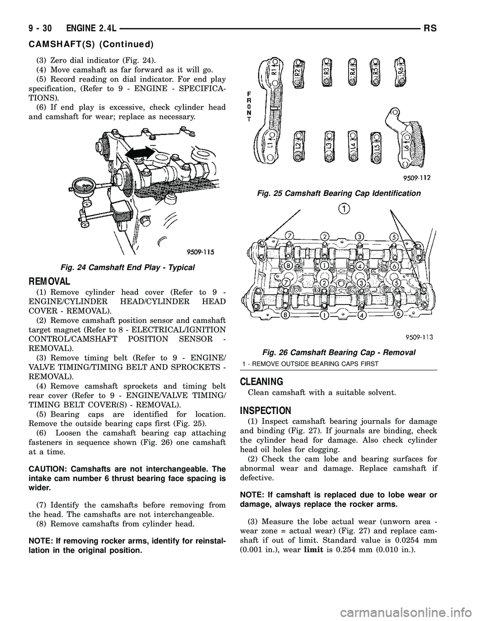
(3) Zero dial indicator (Fig. 24).
(4) Move camshaft as far forward as it will go.
(5) Record reading on dial indicator. For end play
specification, (Refer to 9 - ENGINE - SPECIFICA-
TIONS).
(6) If end play is excessive, check cylinder head
and camshaft for wear; replace as necessary.
REMOVAL
(1) Remove cylinder head cover (Refer to 9 -
ENGINE/CYLINDER HEAD/CYLINDER HEAD
COVER - REMOVAL).
(2) Remove camshaft position sensor and camshaft
target magnet (Refer to 8 - ELECTRICAL/IGNITION
CONTROL/CAMSHAFT POSITION SENSOR -
REMOVAL).
(3) Remove timing belt (Refer to 9 - ENGINE/
VALVE TIMING/TIMING BELT AND SPROCKETS -
REMOVAL).
(4) Remove camshaft sprockets and timing belt
rear cover (Refer to 9 - ENGINE/VALVE TIMING/
TIMING BELT COVER(S) - REMOVAL).
(5) Bearing caps are identified for location.
Remove the outside bearing caps first (Fig. 25).
(6) Loosen the camshaft bearing cap attaching
fasteners in sequence shown (Fig. 26) one camshaft
at a time.
CAUTION: Camshafts are not interchangeable. The
intake cam number 6 thrust bearing face spacing is
wider.
(7) Identify the camshafts before removing from
the head. The camshafts are not interchangeable.
(8) Remove camshafts from cylinder head.
NOTE: If removing rocker arms, identify for reinstal-
lation in the original position.
CLEANING
Clean camshaft with a suitable solvent.
INSPECTION
(1) Inspect camshaft bearing journals for damage
and binding (Fig. 27). If journals are binding, check
the cylinder head for damage. Also check cylinder
head oil holes for clogging.
(2) Check the cam lobe and bearing surfaces for
abnormal wear and damage. Replace camshaft if
defective.
NOTE: If camshaft is replaced due to lobe wear or
damage, always replace the rocker arms.
(3) Measure the lobe actual wear (unworn area -
wear zone = actual wear) (Fig. 27) and replace cam-
shaft if out of limit. Standard value is 0.0254 mm
(0.001 in.), wearlimitis 0.254 mm (0.010 in.).
Fig. 24 Camshaft End Play - Typical
Fig. 25 Camshaft Bearing Cap Identification
Fig. 26 Camshaft Bearing Cap - Removal
1 - REMOVE OUTSIDE BEARING CAPS FIRST
9 - 30 ENGINE 2.4LRS
CAMSHAFT(S) (Continued)
Page 1209 of 2339
INSTALLATION
NOTE: Replace spark plug well seals and bolt
assemblies when installing a new cylinder head
cover gasket.
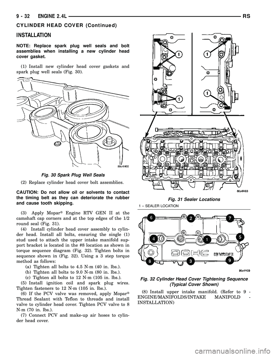
(1) Install new cylinder head cover gaskets and
spark plug well seals (Fig. 30).
(2) Replace cylinder head cover bolt assemblies.
CAUTION: Do not allow oil or solvents to contact
the timing belt as they can deteriorate the rubber
and cause tooth skipping.
(3) Apply MopartEngine RTV GEN II at the
camshaft cap corners and at the top edges of the 1/2
round seal (Fig. 31).
(4) Install cylinder head cover assembly to cylin-
der head. Install all bolts, ensuring the single (1)
stud used to attach the upper intake manifold sup-
port bracket is located in the #8 location as shown in
torque sequence diagram (Fig. 32). Tighten bolts in
sequence shown in (Fig. 32). Using a 3 step torque
method as follows:
(a) Tighten all bolts to 4.5 N´m (40 in. lbs.).
(b) Tighten all bolts to 9.0 N´m (80 in. lbs.).
(c) Tighten all bolts to 12 N´m (105 in. lbs.).
(5) Install ignition coil and spark plug wires.
Tighten fasteners to 12 N´m (105 in. lbs.).
(6) If the PCV valve was removed, apply Mopart
Thread Sealant with Teflon to threads and install
valve to cylinder head cover. Tighten PCV valve to 8
N´m (70 in. lbs.).
(7) Connect PCV and make-up air hoses to cylin-
der head cover.(8) Install upper intake manifold. (Refer to 9 -
ENGINE/MANIFOLDS/INTAKE MANIFOLD -
INSTALLATION)
Fig. 30 Spark Plug Well Seals
Fig. 31 Sealer Locations
1 ± SEALER LOCATION
Fig. 32 Cylinder Head Cover Tightening Sequence
(Typical Cover Shown)
9 - 32 ENGINE 2.4LRS
CYLINDER HEAD COVER (Continued)
Page 1210 of 2339

INTAKE/EXHAUST VALVES &
SEATS
DESCRIPTION
The valves are made of heat resistant steel. They
have chrome plated stems to prevent scuffing. Viton
rubber valve stem seals are integral with the spring
seats. The valves have three-bead lock keepers to
retain springs and to promote valve rotation.
CLEANING
(1) Clean all valves thoroughly and discard
burned, warped and cracked valves.
VALVE SPRINGS & SEALS
REMOVAL
REMOVAL - CYLINDER HEAD ON
(1) Remove cylinder head cover (Refer to 9 -
ENGINE/CYLINDER HEAD/CYLINDER HEAD
COVER(S) - REMOVAL).
(2) Remove camshafts (Refer to 9 - ENGINE/CYL-
INDER HEAD/CAMSHAFT(S) - REMOVAL).
(3) Rotate crankshaft until piston is at TDC on
compression.
(4) With air hose attached to adapter tool installed
in spark plug hole, apply 90-120 psi air pressure.
(5) Using Special Tool MD-998772-A with adapter
6779 (Fig. 33), compress valve springs and remove
valve locks.
(6) Remove valve spring(s).
(7) Remove valve stem seal(s) by a using valve
stem seal tool (Fig. 35).
REMOVAL - CYLINDER HEAD OFF
(1) With cylinder head removed from cylinder
block, compress valve springs using a universal valve
spring compressor.
(2) Remove valve retaining locks, valve spring
retainers, valve stem seals and valve springs.
(3) Before removing valves,remove any burrs
from valve stem lock grooves to prevent dam-
age to the valve guides.Identify valves, locks and
retainers to insure installation in original location.
(4) Inspect the valves. (Refer to 9 - ENGINE/CYL-
INDER HEAD/VALVE SPRINGS - INSPECTION)
INSPECTION
(1) Whenever valves have been removed for inspec-
tion, reconditioning or replacement, valve springs
should be tested for correct tension. Discard the
springs that do not meet specifications. The following
specifications apply to both intake and exhaust
valves springs:
²Valve Closed Nominal TensionÐ76 lbs. @ 38.0
mm (1.50 in.)
²Valve Open Nominal TensionÐ136 lbs. @ 29.75
mm (1.17 in.)
(2) Inspect each valve spring for squareness with a
steel square and surface plate, test springs from both
ends. If the spring is more than 1.5 mm (1/16 inch)
out of square, install a new spring.
INSTALLATION
INSTALLATION - CYLINDER HEAD ON
(1) Install valve seal/valve spring seat assembly
(Fig. 34). Push the assembly down to seat it onto the
valve guide.
(2) Install valve spring and retainer, use Special
Tool MD-998772-A with adapter 6779 to compress
valve springs only enough to install locks (Fig. 33).
Correct alignment of tool is necessary to avoid nick-
ing valve stems.
(3) Remove air hose and install spark plugs.
(4) Install camshafts (Refer to 9 - ENGINE/CYL-
INDER HEAD/CAMSHAFT(S) - INSTALLATION).
(5) Install cylinder head cover (Refer to 9 -
ENGINE/CYLINDER HEAD/CYLINDER HEAD
COVER - INSTALLATION).
INSTALLATION - CYLINDER HEAD OFF
(1) Coat valve stems with clean engine oil and
insert in cylinder head.
(2) Install new valve stem seals on all valves
using a valve stem seal tool (Fig. 35). The valve stem
seals should be pushed firmly and squarely over
valve guide.
Fig. 33 Valve Spring - Removal/Installation
1 - VALVE SPRING COMPRESSOR MD 998772A
2 - AIR HOSE
RSENGINE 2.4L9-33