sensor CHRYSLER CARAVAN 2005 Service Manual
[x] Cancel search | Manufacturer: CHRYSLER, Model Year: 2005, Model line: CARAVAN, Model: CHRYSLER CARAVAN 2005Pages: 2339, PDF Size: 59.69 MB
Page 1404 of 2339
(2) Install sensor and tighten to 27 N´m (20 ft.
lbs.) (Fig. 23).
(3) Connect the electrical connector for the O2 sen-
sor and install onto bracket.
(4) Lower vehicle.
(5) Connect the negative battery cable.
INSTALLATION - UPSTREAM 1/1 - 3.3/3.8L
The engines uses two heated oxygen sensors.
(1) After removing the sensor, the exhaust mani-
fold threads must be cleaned with an 18 mm X 1.5 +
6E tap. If reusing the original sensor, coat the sensor
threads with an anti-seize compound such as Loctite
771- 64 or equivalent. New sensors have compound
on the threads and do not require an additional coat-
ing.
(2) Install sensor and tighten to 27 N´m (20 ft.
lbs.).
(3) Connect the electrical connector for the O2 sen-
sor and install onto bracket.
(4) Connect the electrical connector for the speed
control servo.
(5) Install the speed control servo and bracket
refer to the Speed Control Servo for more informa-
tion.
(6) Connect the speed control vacuum harness to
servo.
(7) Install the battery tray, refer to the Battery
section for more information.
(8) Install battery, refer to the Battery section for
more information.
INSTALLATION DOWNSTREAM 2/1 -
2.4/3.3/3.8L
The O2S is located on the side of the catalytic con-
verter.
Threads of new oxygen sensors are factory coated
with anti-seize compound to aid in removal.DO
NOT add any additional anti-seize compound to
the threads of a new oxygen sensor.
(1) Install sensor and tighten to 27 N´m (20 ft.
lbs.).
(2) Connect the electrical connector.
(3) Lower vehicle.
(4) Install the negative battery cable.
THROTTLE BODY
DESCRIPTION
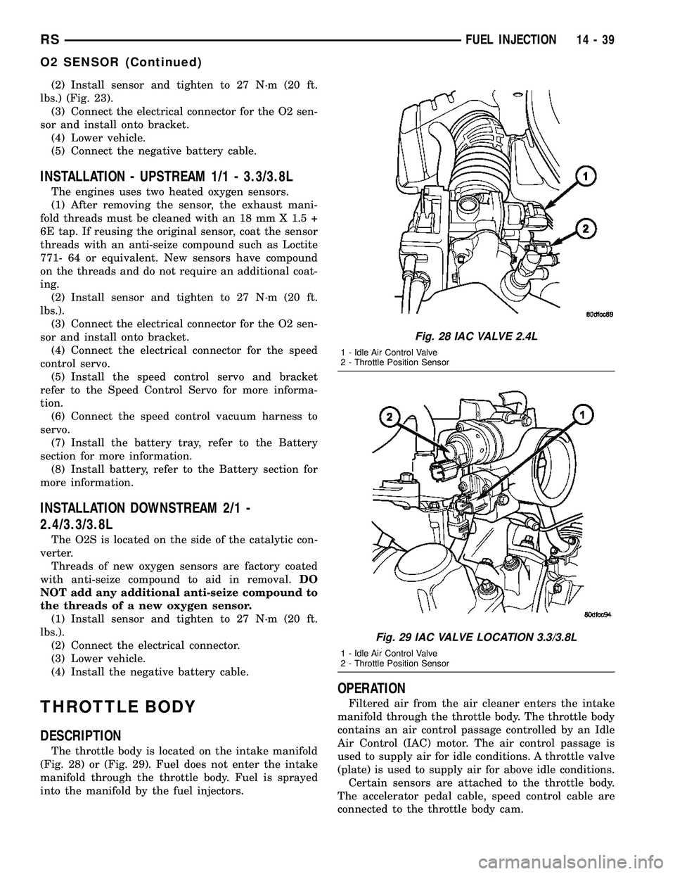
The throttle body is located on the intake manifold
(Fig. 28) or (Fig. 29). Fuel does not enter the intake
manifold through the throttle body. Fuel is sprayed
into the manifold by the fuel injectors.
OPERATION
Filtered air from the air cleaner enters the intake
manifold through the throttle body. The throttle body
contains an air control passage controlled by an Idle
Air Control (IAC) motor. The air control passage is
used to supply air for idle conditions. A throttle valve
(plate) is used to supply air for above idle conditions.
Certain sensors are attached to the throttle body.
The accelerator pedal cable, speed control cable are
connected to the throttle body cam.
Fig. 28 IAC VALVE 2.4L
1 - Idle Air Control Valve
2 - Throttle Position Sensor
Fig. 29 IAC VALVE LOCATION 3.3/3.8L
1 - Idle Air Control Valve
2 - Throttle Position Sensor
RSFUEL INJECTION14-39
O2 SENSOR (Continued)
Page 1405 of 2339

A (factory adjusted) set screw is used to mechani-
cally limit the position of the throttle body throttle
plate.Never attempt to adjust the engine idle
speed using this screw.All idle speed functions are
controlled by the PCM.
REMOVAL
(1) Disconnect negative cable from battery cable.
(2) Remove air inlet to throttle body hose clamp.
(3) Remove throttle and the speed control (if
equipped) cables from lever and bracket.
(4) Disconnect electrical connectors from the idle
air control motor and throttle position sensor (TPS)
(Fig. 28) or (Fig. 29).
(5) Remove throttle body to intake manifold
attaching bolts.
(6) Remove throttle body and gasket.
INSTALLATION
(1) Install a new gasket, if required.
(2) Install throttle body.
(3) Tighten throttle body mounting bolts. The 2.4L
to 28.2 N´m (250 50 in. lbs.) torque, The 3.3/3.8L to
11.6 N´m (105 20 in. lbs.) torque.
(4) Connect electrical connectors to the idle air
control motor and throttle position sensor (TPS) (Fig.
28) or (Fig. 29).
(5) Install air inlet to throttle body hose clamp and
tighten.
(6) Connect negative cable to battery cable.
THROTTLE CONTROL CABLE
REMOVAL
(1) Working from the engine compartment, hold
the throttle body throttle lever in the wide open posi-
tion.
(2) Remove the throttle cable from the throttle
body cam.
(3) From inside the vehicle, hold up the pedal and
remove the cable retainer and throttle cable from the
upper end of the pedal shaft.
(4) Remove retainer clip from throttle cable and
grommet at dash panel.
(5) From the engine compartment, pull the throttle
cable and gromment out of the dash panel.
(6) Remove the throttle cable from throttle bracket
by carefully compressing both retaining ears simulta-
neously then gently pull the throttle cable from
throttle bracket or if it is the slide snap design you
have to slide the locking tab out of the hole and then
slide the cable assembly out of the bracket.
INSTALLATION
(1) From the engine compartment, push the hous-
ing end fitting and grommet into the dash panel.In-
stall gromment into the dash panel.
(2) Install the cable housing (throttle body end)
into the cable mounting bracket on the engine.
(3) From inside the vehicle, hold up the pedal and
install throttle cable and cable retainer in the upper
end of the pedal shaft.
(4) At the dash panel, install the cable retainer
clip between the end of the throttle cable fitting and
grommet
(5) From the engine compartment, rotate the
throttle lever wide open and install the throttle
cable.
THROTTLE POSITION SENSOR
DESCRIPTION
The throttle position sensor mounts to the side of
the throttle body (Fig. 30) or (Fig. 31).The sensor
connects to the throttle blade shaft. The TPS is a
variable resistor that provides the Powertrain Con-
trol Module (PCM) with an input signal (voltage).
Fig. 30 Throttle Position SensorÐ2.4L Engine
1 - Idle Air Control Valve
2 - Throttle Position Sensor
14 - 40 FUEL INJECTIONRS
THROTTLE BODY (Continued)
Page 1406 of 2339

OPERATION
The signal represents throttle blade position. As
the position of the throttle blade changes, the resis-
tance of the TPS changes.
The PCM supplies approximately 5 volts to the
TPS. The TPS output voltage (input signal to the
powertrain control module) represents throttle blade
position. The TPS output voltage to the PCM varies
from approximately 0.6 volt at minimum throttle
opening (idle) to a maximum of 4.5 volts at wide open
throttle.Along with inputs from other sensors, the PCM
uses the TPS input to determine current engine oper-
ating conditions. The PCM also adjusts fuel injector
pulse width and ignition timing based on these
inputs.
REMOVAL - 3.3/3.8L
(1) Disconnect the negative battery cable.
(2) Remove the electrical connector from the Inlet
Air Temperature sensor.
(3) Remove the air cleaner box lid. Remove hose
from throttle body.
(4) Disconnect the electrical connector at TPS.
(5) Disconnect the electrical connector at IAC.
(6) Remove the throttle and speed control cables
from throttle body.
(7) Remove 3 mounting bolts from throttle body.
(8) Remove throttle body.
(9) Disconnect the purge vacuum line from the
throttle body.
(10) Remove TPS from throttle body.
INSTALLATION - 3.3/3.8L
(1) Install TPS to throttle body.
(2) Disconnect the purge vacuum line from the
throttle body.
(3) Install throttle body.
(4) Install 3 mounting bolts from throttle body.
Tighten bolts.
(5) Install the throttle and speed control cables to
throttle body.
(6) Connect the electrical connector at TPS.
(7) Connect the electrical connector at IAC.
(8) Install the air cleaner box lid. Install hose to
throttle body.
(9) Install the electrical connector to the Inlet Air
Temperature sensor.
(10) Connect the negative battery cable.
Fig. 31 Throttle Position SensorÐ3.3/3.8L Engine
1 - Idle Air Control Valve
2 - Throttle Position Sensor
RSFUEL INJECTION14-41
THROTTLE POSITION SENSOR (Continued)
Page 1445 of 2339

Read the fluid level through the side of the power
steering fluid reservoir. The fluid level should indi-
cateªFILL RANGEºwhen the fluid is at a temper-
ature of approximately 21ÉC to 27ÉC (70ÉF to 80ÉF).
(1) Wipe the filler cap and area clean, then remove
the cap.
(2) Fill the fluid reservoir to the proper level and
let the fluid settle for at least two (2) minutes.
(3) Start the engine and let run for a few seconds,
then turn the engine off.
(4) Add fluid if necessary. Repeat the above steps
until the fluid level remains constant after running
the engine.
(5) Raise the front wheels off the ground.
(6) Start the engine.
(7) Slowly turn the steering wheel right and left,
lightly contacting the wheel stops.
(8) Add fluid if necessary.
(9) Lower the vehicle, then turn the steering wheel
slowly from lock-to-lock.
(10) Stop the engine. Check the fluid level and
refill as required.
(11) If the fluid is extremely foamy, allow the vehi-
cle to stabilize a few minutes, then repeat the above
procedure.
REMOVAL
REMOVAL - PUMP (2.4L ENGINE)
(1) Remove the (-) negative battery cable from the
battery and isolate cable.
(2) Remove the cap from the power steering fluid
reservoir.
(3) Using a siphon pump, remove as much power
steering fluid as possible from the power steering
fluid reservoir.
(4) Raise the vehicle on jack stands or centered on
a frame contact type hoist. See Hoisting in Lubrica-
tion and Maintenance.
(5) Disconnect the oxygen sensor wiring harness
from the vehicle wiring harness at the rear engine
mount bracket.
NOTE: The exhaust system needs to be removed
from the engine to allow for an area to remove the
power steering pump from the vehicle.(6) Remove the four bolts and flag nuts securing
the catalytic converter from the exhaust manifold
(Fig. 3).
(7) Disconnect all the exhaust system isolators/
hangers from the brackets on the exhaust system (2
at the mufflers and 1 at the resonator) (Fig. 4).
(8) Remove the exhaust system by moving it as far
rearward, then lowering the front below the cross-
member and out of the vehicle.
(9) Remove the power steering fluid supply hose
from the fitting on the power steering pump. Drain
off excess power steering fluid from hose.
(10) Move the heat sleeve on the power steering
return hose to expose the hose connection at the
pump (Fig. 5). Remove the hose from the power
steering Pump. Allow the remaining power steering
fluid to drain from the power steering pump and res-
ervoir through the removed return hose.
(11) Remove the power steering fluid pressure line
from the power steering pump (Fig. 6). Drain excess
power steering fluid from tube.
Fig. 3 Catalytic Converter to Exhaust Manifold
1 - CATALYTIC CONVERTER
2 - BOLT
3 - GASKET
4 - FLAG NUT
19 - 38 PUMPRS
PUMP (Continued)
Page 1450 of 2339

INSTALLATION
INSTALLATION - PUMP (2.4L ENGINE)
(1) Install power steering pump back in vehicle
using the reverse order of its removal through the
exhaust tunnel of the vehicle.
(2) Install the power steering pump on its cast
mounting bracket (Fig. 7), then install the nut and
bolt attaching the front bracket to the cast bracket
(Fig. 8).Do not fully tighten at this time..
(3) Install the rear nut (Fig. 7).
(4) Install the power steering pump drive belt on
pulley and adjust (Refer to 7 - COOLING/ACCES-
SORY DRIVE/DRIVE BELTS - INSTALLATION).
(5) Tighten the two adjustment slot bolts and the
one pivot bolt to 54 N´m (40 ft. lbs.) torque.
(6) Install the accessory drive splash shield.
NOTE: Before installing power steering fluid pres-
sure hose on power steering pump, inspect the
O-ring on the pressure hose for damage and
replace if necessary.
(7) Install the power steering fluid pressure line
onto the output fitting of the power steering pump
(Fig. 6). Tighten the pressure line to pump fitting
tube nut to a torque of 31 N´m (275 in. lbs.).
(8) Install the power steering fluid low pressure
return hose on the power steering pump low pressure
fitting (Fig. 6).Be sure hose clamps are properly
reinstalled.
(9) Install the power steering fluid supply hose on
the power steering pump fluid fitting.Be sure hose
is clear of accessory drive belts all hose clamps
are properly reinstalled.
CAUTION: Heat sleeve must cover entire rubber
portion of return hose to ensure desired thermal
protection from exhaust.
(10) Properly position the protective heat sleeve
over the power steering return hose. Securely tie
strap the heat sleeve to the power steering hose to
keep in it's proper position.
(11)
Install the exhaust system (Fig. 4). Install all
exhaust system isolators/hangers on the exhaust sys-
tem brackets, then the four bolts and flag nuts (Fig. 3).
(12) Connect the oxygen sensor wiring harness to
the vehicle wiring harness.
(13) Lower vehicle.
(14) Connect the negative battery cable on the
negative battery post.
(15) Perform the POWER STEERING PUMP INI-
TIAL OPERATION procedure to properly fill and
bleed the power steering system. (Refer to 19 -
STEERING/PUMP - STANDARD PROCEDURE)
(16) Inspect for leaks.
INSTALLATION - PUMP (3.3L/3.8L ENGINE)
(1) Install power steering pump back in vehicle
using the reverse order of its removal through the
engine compartment of the vehicle.
(2) Install the power steering pump on its mount-
ing bracket.
(3) Install the 3 front power steering pump mount-
ing bolts (Fig. 11). Tighten the 3 front power steering
pump mounting bolts to a torque of 54 N´m (40 ft.
lbs.).
NOTE: Before installing power steering pressure
hose on power steering pump, inspect the O-ring
on the power steering pressure hose for damage
and replace if required.
(4) Install the power steering fluid pressure line
into the pressure output fitting of the power steering
pump (Fig. 10).Do not fully tighten tube nut at
this time.
(5) Install the power steering fluid supply hose on
the power steering pump supply fitting (Fig. 10).Be
sure hose clamp is properly installed.
(6) Raise the vehicle.
(7) Install the routing clip on the engine for the
pressure hose (Fig. 9) and tighten fastener.
(8) Install the serpentine drive belt (Refer to 7 -
COOLING/ACCESSORY DRIVE/DRIVE BELTS -
INSTALLATION).
(9) Install the drive belt splash shield.
(10) Lower the vehicle.
(11) Tighten the pressure line to pump pressure
fitting tube nut to a torque of 31 N´m (275 in. lbs.).
(12) Install the wiper module (unit)(Refer to 8 -
ELECTRICAL/WIPERS/WASHERS/WIPER MOD-
ULE - INSTALLATION).
(13) Connect the negative battery cable on the
negative battery post.
(14) Fill and bleed the power steering system
using the Power Steering Pump Initial Operation
Procedure (Refer to 19 - STEERING/PUMP - STAN-
DARD PROCEDURE).
(15) Inspect for leaks.
INSTALLATION - PUMP (DIESEL)
(1) Install the power steering pump on its cast
mounting bracket.
(2) Install the three front power steering pump
mounting bolts. Tighten the mounting bolts to a
torque of 54 N´m (40 ft. lbs.).
(3) Install the rear mounting bolt fastening the
stamped bracket to the cast bracket (Fig. 13).
Tighten the mounting bolt to a torque of 54 N´m (40
ft. lbs.).
RSPUMP19-43
PUMP (Continued)
Page 1463 of 2339
SPEED SENSOR - INPUT
DESCRIPTION........................120
OPERATION..........................120
REMOVAL............................121
INSTALLATION........................121
SPEED SENSOR - OUTPUT
DESCRIPTION........................122
OPERATION..........................122
REMOVAL............................123
INSTALLATION........................123
TORQUE CONVERTER
DESCRIPTION........................124
OPERATION..........................128
REMOVAL............................129
INSTALLATION........................129TRANSMISSION CONTROL RELAY
DESCRIPTION........................130
OPERATION..........................130
TRANSMISSION RANGE SENSOR
DESCRIPTION........................130
OPERATION..........................131
REMOVAL............................131
INSTALLATION........................131
VALVE BODY
DESCRIPTION........................132
OPERATION..........................132
REMOVAL............................133
DISASSEMBLY........................135
ASSEMBLY...........................139
INSTALLATION........................144
40TE AUTOMATIC
TRANSAXLE
DESCRIPTION
The 40TE (Fig. 1) is a four-speed transaxle that is
a conventional hydraulic/mechanical assembly with
an integral differential, and is controlled with adap-
tive electronic controls and monitors. The hydraulic
system of the transaxle consists of the transaxle
fluid, fluid passages, hydraulic valves, and various
line pressure control components. An input clutch
assembly which houses the underdrive, overdrive,
and reverse clutches is used. It also utilizes separate
holding clutches: 2nd/4th gear and Low/Reverse. The
primary mechanical components of the transaxle con-
sist of the following:
²Three multiple disc input clutches
²Two multiple disc holding clutches
²Four hydraulic accumulators
²Two planetary gear sets
²Hydraulic oil pump
²Valve body²Solenoid/Pressure switch assembly
²Integral differential assembly
Control of the transaxle is accomplished by fully
adaptive electronics. Optimum shift scheduling is
accomplished through continuous real-time sensor
feedback information provided to the Powertrain
Control Module (PCM) or Transmission Control Mod-
ule (TCM).
The PCM/TCM is the heart of the electronic control
system and relies on information from various direct
and indirect inputs (sensors, switches, etc.) to deter-
mine driver demand and vehicle operating condi-
tions. With this information, the PCM/TCM can
calculate and perform timely and quality shifts
through various output or control devices (solenoid
pack, transmission control relay, etc.).
The PCM/TCM also performs certain self-diagnos-
tic functions and provides comprehensive information
(sensor data, DTC's, etc.) which is helpful in proper
diagnosis and repair. This information can be viewed
with the DRB scan tool.
21 - 2 40TE AUTOMATIC TRANSAXLERS
Page 1464 of 2339
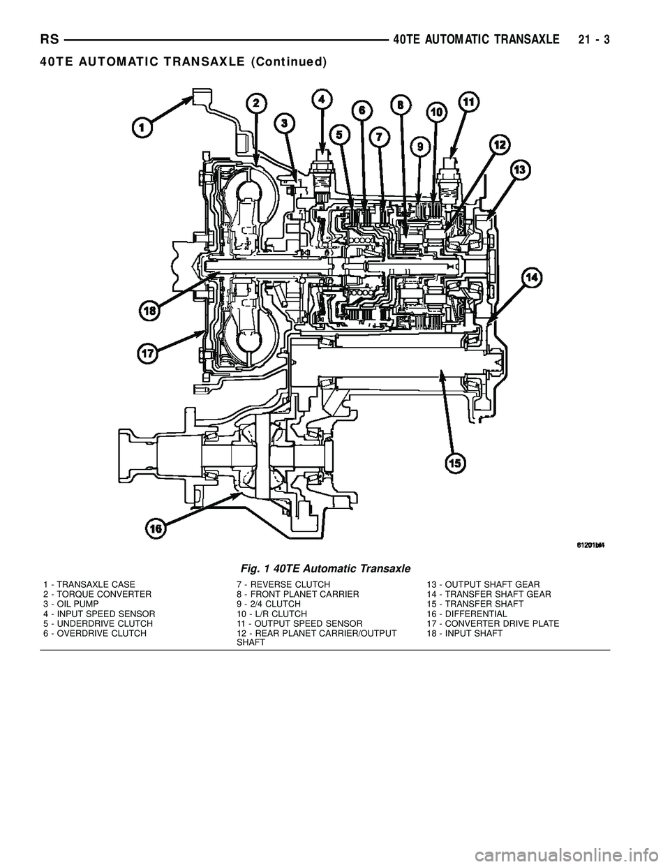
Fig. 1 40TE Automatic Transaxle
1 - TRANSAXLE CASE 7 - REVERSE CLUTCH 13 - OUTPUT SHAFT GEAR
2 - TORQUE CONVERTER 8 - FRONT PLANET CARRIER 14 - TRANSFER SHAFT GEAR
3 - OIL PUMP 9 - 2/4 CLUTCH 15 - TRANSFER SHAFT
4 - INPUT SPEED SENSOR 10 - L/R CLUTCH 16 - DIFFERENTIAL
5 - UNDERDRIVE CLUTCH 11 - OUTPUT SPEED SENSOR 17 - CONVERTER DRIVE PLATE
6 - OVERDRIVE CLUTCH 12 - REAR PLANET CARRIER/OUTPUT
SHAFT18 - INPUT SHAFT
RS40TE AUTOMATIC TRANSAXLE21-3
40TE AUTOMATIC TRANSAXLE (Continued)
Page 1471 of 2339
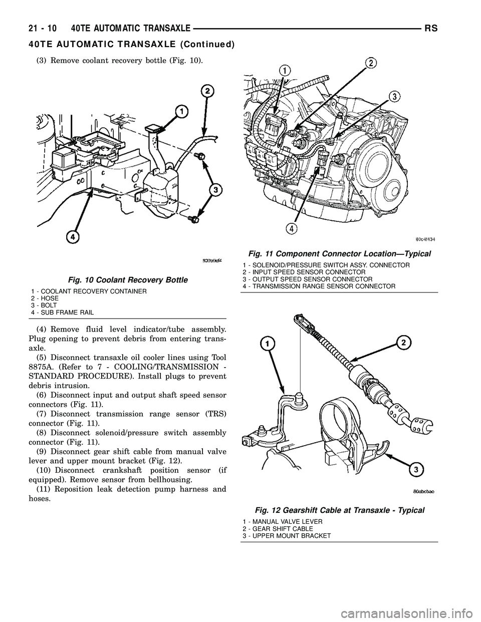
(3) Remove coolant recovery bottle (Fig. 10).
(4) Remove fluid level indicator/tube assembly.
Plug opening to prevent debris from entering trans-
axle.
(5) Disconnect transaxle oil cooler lines using Tool
8875A. (Refer to 7 - COOLING/TRANSMISSION -
STANDARD PROCEDURE). Install plugs to prevent
debris intrusion.
(6) Disconnect input and output shaft speed sensor
connectors (Fig. 11).
(7) Disconnect transmission range sensor (TRS)
connector (Fig. 11).
(8) Disconnect solenoid/pressure switch assembly
connector (Fig. 11).
(9) Disconnect gear shift cable from manual valve
lever and upper mount bracket (Fig. 12).
(10) Disconnect crankshaft position sensor (if
equipped). Remove sensor from bellhousing.
(11) Reposition leak detection pump harness and
hoses.
Fig. 10 Coolant Recovery Bottle
1 - COOLANT RECOVERY CONTAINER
2 - HOSE
3 - BOLT
4 - SUB FRAME RAIL
Fig. 11 Component Connector LocationÐTypical
1 - SOLENOID/PRESSURE SWITCH ASSY. CONNECTOR
2 - INPUT SPEED SENSOR CONNECTOR
3 - OUTPUT SPEED SENSOR CONNECTOR
4 - TRANSMISSION RANGE SENSOR CONNECTOR
Fig. 12 Gearshift Cable at Transaxle - Typical
1 - MANUAL VALVE LEVER
2 - GEAR SHIFT CABLE
3 - UPPER MOUNT BRACKET
21 - 10 40TE AUTOMATIC TRANSAXLERS
40TE AUTOMATIC TRANSAXLE (Continued)
Page 1473 of 2339
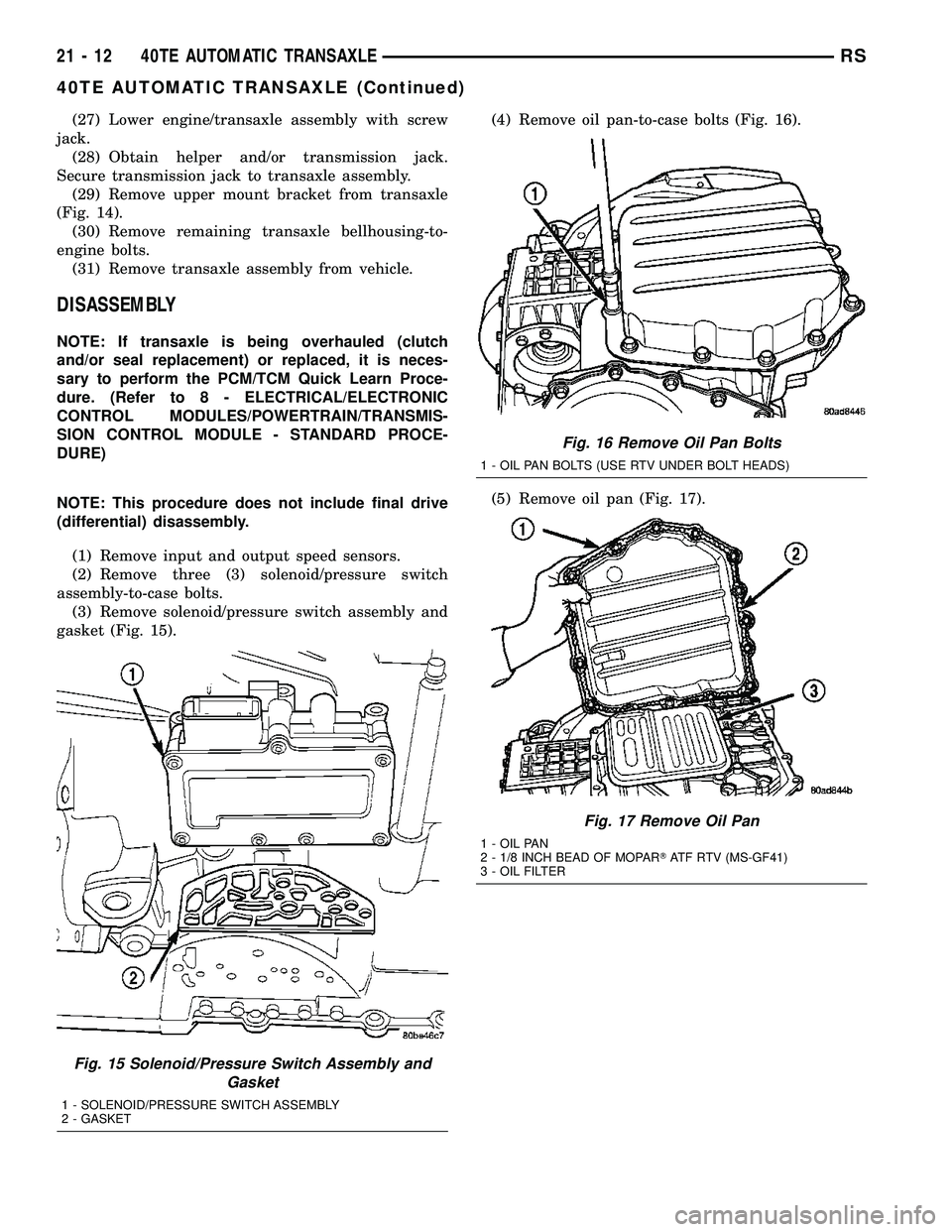
(27) Lower engine/transaxle assembly with screw
jack.
(28) Obtain helper and/or transmission jack.
Secure transmission jack to transaxle assembly.
(29) Remove upper mount bracket from transaxle
(Fig. 14).
(30) Remove remaining transaxle bellhousing-to-
engine bolts.
(31) Remove transaxle assembly from vehicle.
DISASSEMBLY
NOTE: If transaxle is being overhauled (clutch
and/or seal replacement) or replaced, it is neces-
sary to perform the PCM/TCM Quick Learn Proce-
dure. (Refer to 8 - ELECTRICAL/ELECTRONIC
CONTROL MODULES/POWERTRAIN/TRANSMIS-
SION CONTROL MODULE - STANDARD PROCE-
DURE)
NOTE: This procedure does not include final drive
(differential) disassembly.
(1) Remove input and output speed sensors.
(2) Remove three (3) solenoid/pressure switch
assembly-to-case bolts.
(3) Remove solenoid/pressure switch assembly and
gasket (Fig. 15).(4) Remove oil pan-to-case bolts (Fig. 16).
(5) Remove oil pan (Fig. 17).
Fig. 15 Solenoid/Pressure Switch Assembly and
Gasket
1 - SOLENOID/PRESSURE SWITCH ASSEMBLY
2 - GASKET
Fig. 16 Remove Oil Pan Bolts
1 - OIL PAN BOLTS (USE RTV UNDER BOLT HEADS)
Fig. 17 Remove Oil Pan
1 - OIL PAN
2 - 1/8 INCH BEAD OF MOPARTATF RTV (MS-GF41)
3 - OIL FILTER
21 - 12 40TE AUTOMATIC TRANSAXLERS
40TE AUTOMATIC TRANSAXLE (Continued)
Page 1476 of 2339

(14) Measure input shaft end play. Place transaxle
so input shaft is vertical. Set up end play set and
dial indicator as shown in (Fig. 27).Input shaft end
play should be within 0.13-0.64 mm (0.005-0.025
in.)If outside of this range, a #4 thrust plate change
is required. Record indicator reading for reference
upon reassembly.(15) Remove oil pump-to-case bolts (Fig. 28).
CAUTION: Be sure input speed sensor is removed
before removing oil pump.
(16) Install pullers Tool C-3752 as shown in (Fig.
29).
Fig. 26 Low/Reverse Accumulator
1 - PISTON
2 - RETURN SPRINGS
Fig. 27 Measure Input Shaft End Play Using Tool
8266ÐTypical
1 - TOOL 8266±8
2 - TOOL 8266±2
3 - TOOL C-3339
Fig. 28 Remove Oil Pump-to-Case Bolts
1 - PUMP ATTACHING BOLTS
2 - PUMP HOUSING
Fig. 29 Install Tool C-3752
1 - PULLERS TOOL C-3752
2 - PUMP
RS40TE AUTOMATIC TRANSAXLE21-15
40TE AUTOMATIC TRANSAXLE (Continued)