sensor CHRYSLER CARAVAN 2005 Service Manual
[x] Cancel search | Manufacturer: CHRYSLER, Model Year: 2005, Model line: CARAVAN, Model: CHRYSLER CARAVAN 2005Pages: 2339, PDF Size: 59.69 MB
Page 1733 of 2339
REMOVAL
(1) Disconnect battery negative cable.
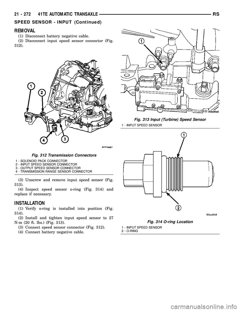
(2) Disconnect input speed sensor connector (Fig.
312).
(3) Unscrew and remove input speed sensor (Fig.
313).
(4) Inspect speed sensor o-ring (Fig. 314) and
replace if necessary.
INSTALLATION
(1) Verify o-ring is installed into position (Fig.
314).
(2) Install and tighten input speed sensor to 27
N´m (20 ft. lbs.) (Fig. 313).
(3) Connect speed sensor connector (Fig. 312).
(4) Connect battery negative cable.
Fig. 312 Transmission Connectors
1 - SOLENOID PACK CONNECTOR
2 - INPUT SPEED SENSOR CONNECTOR
3 - OUTPUT SPEED SENSOR CONNECTOR
4 - TRANSMISSION RANGE SENSOR CONNECTOR
Fig. 313 Input (Turbine) Speed Sensor
1 - INPUT SPEED SENSOR
Fig. 314 O-ring Location
1 - INPUT SPEED SENSOR
2 - O-RING
21 - 272 41TE AUTOMATIC TRANSAXLERS
SPEED SENSOR - INPUT (Continued)
Page 1734 of 2339
SPEED SENSOR - OUTPUT
DESCRIPTION
The Output Speed Sensor is a two-wire magnetic
pickup device that generates an AC signal as rotation
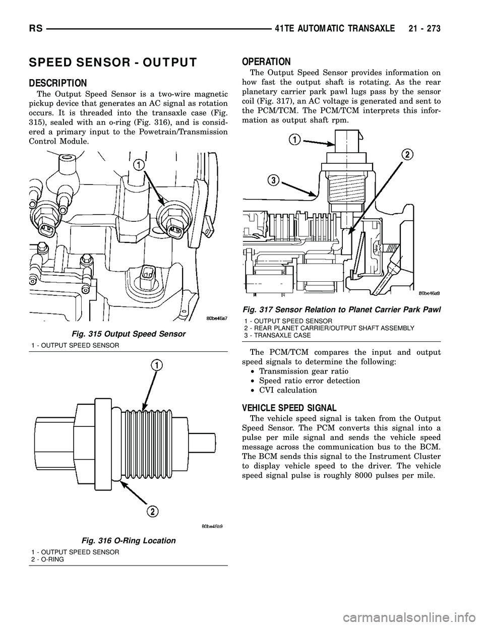
occurs. It is threaded into the transaxle case (Fig.
315), sealed with an o-ring (Fig. 316), and is consid-
ered a primary input to the Powetrain/Transmission
Control Module.
OPERATION
The Output Speed Sensor provides information on
how fast the output shaft is rotating. As the rear
planetary carrier park pawl lugs pass by the sensor
coil (Fig. 317), an AC voltage is generated and sent to
the PCM/TCM. The PCM/TCM interprets this infor-
mation as output shaft rpm.
The PCM/TCM compares the input and output
speed signals to determine the following:
²Transmission gear ratio
²Speed ratio error detection
²CVI calculation
VEHICLE SPEED SIGNAL
The vehicle speed signal is taken from the Output
Speed Sensor. The PCM converts this signal into a
pulse per mile signal and sends the vehicle speed
message across the communication bus to the BCM.
The BCM sends this signal to the Instrument Cluster
to display vehicle speed to the driver. The vehicle
speed signal pulse is roughly 8000 pulses per mile.
Fig. 315 Output Speed Sensor
1 - OUTPUT SPEED SENSOR
Fig. 316 O-Ring Location
1 - OUTPUT SPEED SENSOR
2 - O-RING
Fig. 317 Sensor Relation to Planet Carrier Park Pawl
1 - OUTPUT SPEED SENSOR
2 - REAR PLANET CARRIER/OUTPUT SHAFT ASSEMBLY
3 - TRANSAXLE CASE
RS41TE AUTOMATIC TRANSAXLE21 - 273
Page 1735 of 2339
REMOVAL
(1) Disconnect battery negative cable.
(2) Raise vehicle on hoist.
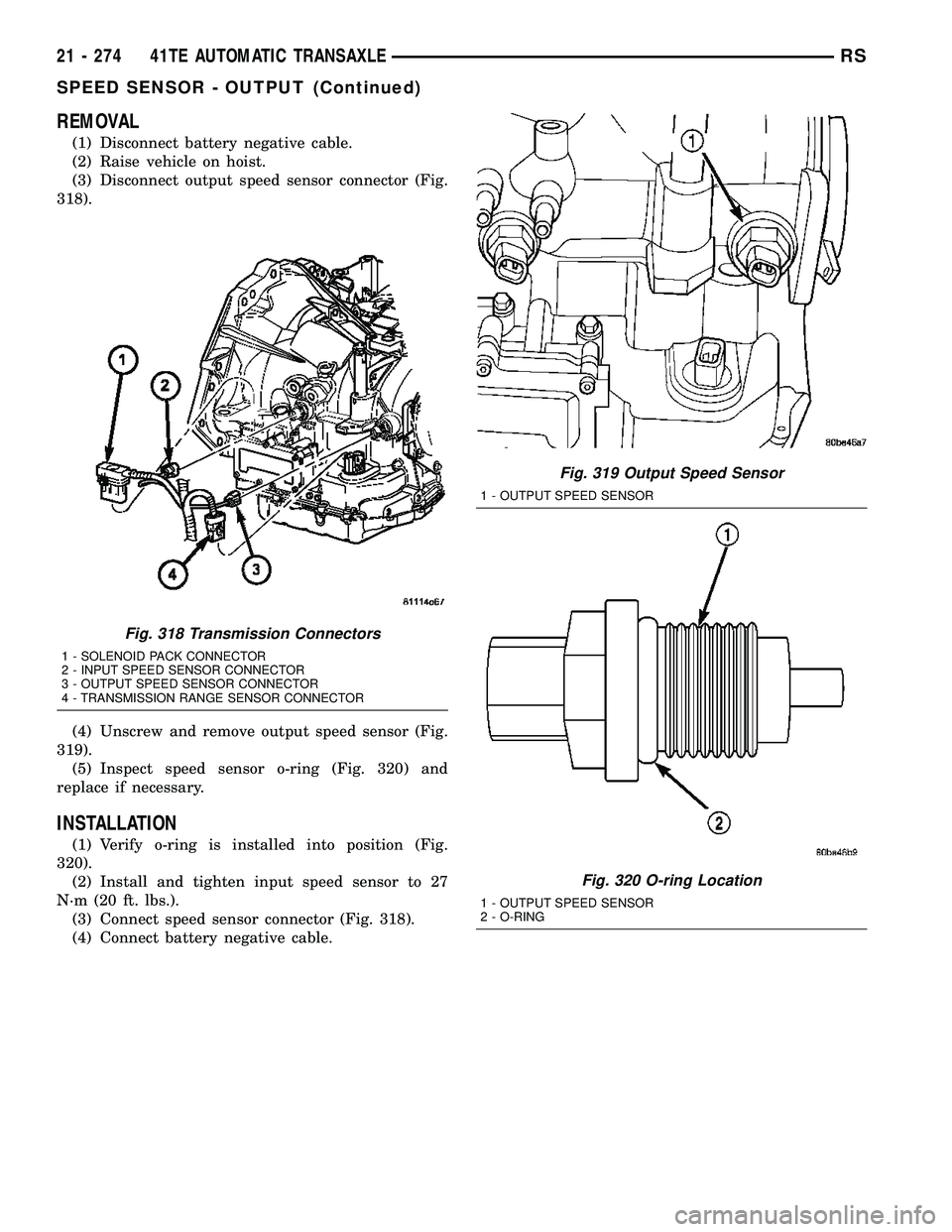
(3) Disconnect output speed sensor connector (Fig.
318).
(4) Unscrew and remove output speed sensor (Fig.
319).
(5) Inspect speed sensor o-ring (Fig. 320) and
replace if necessary.
INSTALLATION
(1) Verify o-ring is installed into position (Fig.
320).
(2) Install and tighten input speed sensor to 27
N´m (20 ft. lbs.).
(3) Connect speed sensor connector (Fig. 318).
(4) Connect battery negative cable.
Fig. 318 Transmission Connectors
1 - SOLENOID PACK CONNECTOR
2 - INPUT SPEED SENSOR CONNECTOR
3 - OUTPUT SPEED SENSOR CONNECTOR
4 - TRANSMISSION RANGE SENSOR CONNECTOR
Fig. 319 Output Speed Sensor
1 - OUTPUT SPEED SENSOR
Fig. 320 O-ring Location
1 - OUTPUT SPEED SENSOR
2 - O-RING
21 - 274 41TE AUTOMATIC TRANSAXLERS
SPEED SENSOR - OUTPUT (Continued)
Page 1742 of 2339
TRANSMISSION CONTROL
RELAY
DESCRIPTION
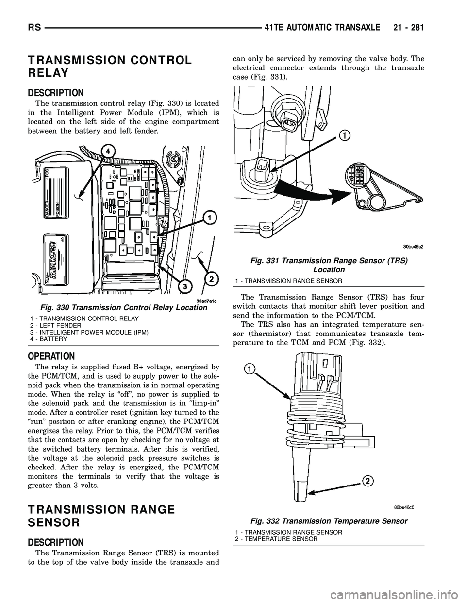
The transmission control relay (Fig. 330) is located
in the Intelligent Power Module (IPM), which is
located on the left side of the engine compartment
between the battery and left fender.
OPERATION
The relay is supplied fused B+ voltage, energized by
the PCM/TCM, and is used to supply power to the sole-
noid pack when the transmission is in normal operating
mode. When the relay is ªoffº, no power is supplied to
the solenoid pack and the transmission is in ªlimp-inº
mode. After a controller reset (ignition key turned to the
ªrunº position or after cranking engine), the PCM/TCM
energizes the relay. Prior to this, the PCM/TCM verifies
that the contacts are open by checking for no voltage at
the switched battery terminals. After this is verified,
the voltage at the solenoid pack pressure switches is
checked. After the relay is energized, the PCM/TCM
monitors the terminals to verify that the voltage is
greater than 3 volts.
TRANSMISSION RANGE
SENSOR
DESCRIPTION
The Transmission Range Sensor (TRS) is mounted
to the top of the valve body inside the transaxle andcan only be serviced by removing the valve body. The
electrical connector extends through the transaxle
case (Fig. 331).
The Transmission Range Sensor (TRS) has four
switch contacts that monitor shift lever position and
send the information to the PCM/TCM.
The TRS also has an integrated temperature sen-
sor (thermistor) that communicates transaxle tem-
perature to the TCM and PCM (Fig. 332).
Fig. 330 Transmission Control Relay Location
1 - TRANSMISSION CONTROL RELAY
2 - LEFT FENDER
3 - INTELLIGENT POWER MODULE (IPM)
4 - BATTERY
Fig. 331 Transmission Range Sensor (TRS)
Location
1 - TRANSMISSION RANGE SENSOR
Fig. 332 Transmission Temperature Sensor
1 - TRANSMISSION RANGE SENSOR
2 - TEMPERATURE SENSOR
RS41TE AUTOMATIC TRANSAXLE21 - 281
Page 1743 of 2339
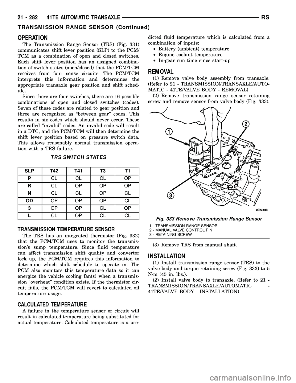
OPERATION
The Transmission Range Sensor (TRS) (Fig. 331)
communicates shift lever position (SLP) to the PCM/
TCM as a combination of open and closed switches.
Each shift lever position has an assigned combina-
tion of switch states (open/closed) that the PCM/TCM
receives from four sense circuits. The PCM/TCM
interprets this information and determines the
appropriate transaxle gear position and shift sched-
ule.
Since there are four switches, there are 16 possible
combinations of open and closed switches (codes).
Seven of these codes are related to gear position and
three are recognized as ªbetween gearº codes. This
results in six codes which should never occur. These
are called ªinvalidº codes. An invalid code will result
in a DTC, and the PCM/TCM will then determine the
shift lever position based on pressure switch data.
This allows reasonably normal transmission opera-
tion with a TRS failure.
TRS SWITCH STATES
SLP T42 T41 T3 T1
PCL CL CL OP
RCL OP OP OP
NCL CL OP CL
ODOP OP OP CL
3OP OP CL OP
LCL OP CL CL
TRANSMISSION TEMPERATURE SENSOR
The TRS has an integrated thermistor (Fig. 332)
that the PCM/TCM uses to monitor the transmis-
sion's sump temperature. Since fluid temperature
can affect transmission shift quality and convertor
lock up, the PCM/TCM requires this information to
determine which shift schedule to operate in. The
PCM also monitors this temperature data so it can
energize the vehicle cooling fan(s) when a transmis-
sion ªoverheatº condition exists. If the thermistor cir-
cuit fails, the PCM/TCM will revert to calculated oil
temperature usage.
CALCULATED TEMPERATURE
A failure in the temperature sensor or circuit will
result in calculated temperature being substituted for
actual temperature. Calculated temperature is a pre-dicted fluid temperature which is calculated from a
combination of inputs:
²Battery (ambient) temperature
²Engine coolant temperature
²In-gear run time since start-up
REMOVAL
(1) Remove valve body assembly from transaxle.
(Refer to 21 - TRANSMISSION/TRANSAXLE/AUTO-
MATIC - 41TE/VALVE BODY - REMOVAL)
(2) Remove transmission range sensor retaining
screw and remove sensor from valve body (Fig. 333).
(3) Remove TRS from manual shaft.
INSTALLATION
(1) Install transmission range sensor (TRS) to the
valve body and torque retaining screw (Fig. 333) to 5
N´m (45 in. lbs.).
(2) Install valve body to transaxle. (Refer to 21 -
TRANSMISSION/TRANSAXLE/AUTOMATIC -
41TE/VALVE BODY - INSTALLATION)
Fig. 333 Remove Transmission Range Sensor
1 - TRANSMISSION RANGE SENSOR
2 - MANUAL VALVE CONTROL PIN
3 - RETAINING SCREW
21 - 282 41TE AUTOMATIC TRANSAXLERS
TRANSMISSION RANGE SENSOR (Continued)
Page 1747 of 2339
DISASSEMBLY
NOTE: If valve body assembly is being recondi-
tioned, the PCM/TCM Quick Learn Procedure must
be performed. (Refer to 8 - ELECTRICAL/ELEC-
TRONIC CONTROL MODULES/TRANSMISSION
CONTROL MODULE - STANDARD PROCEDURE)
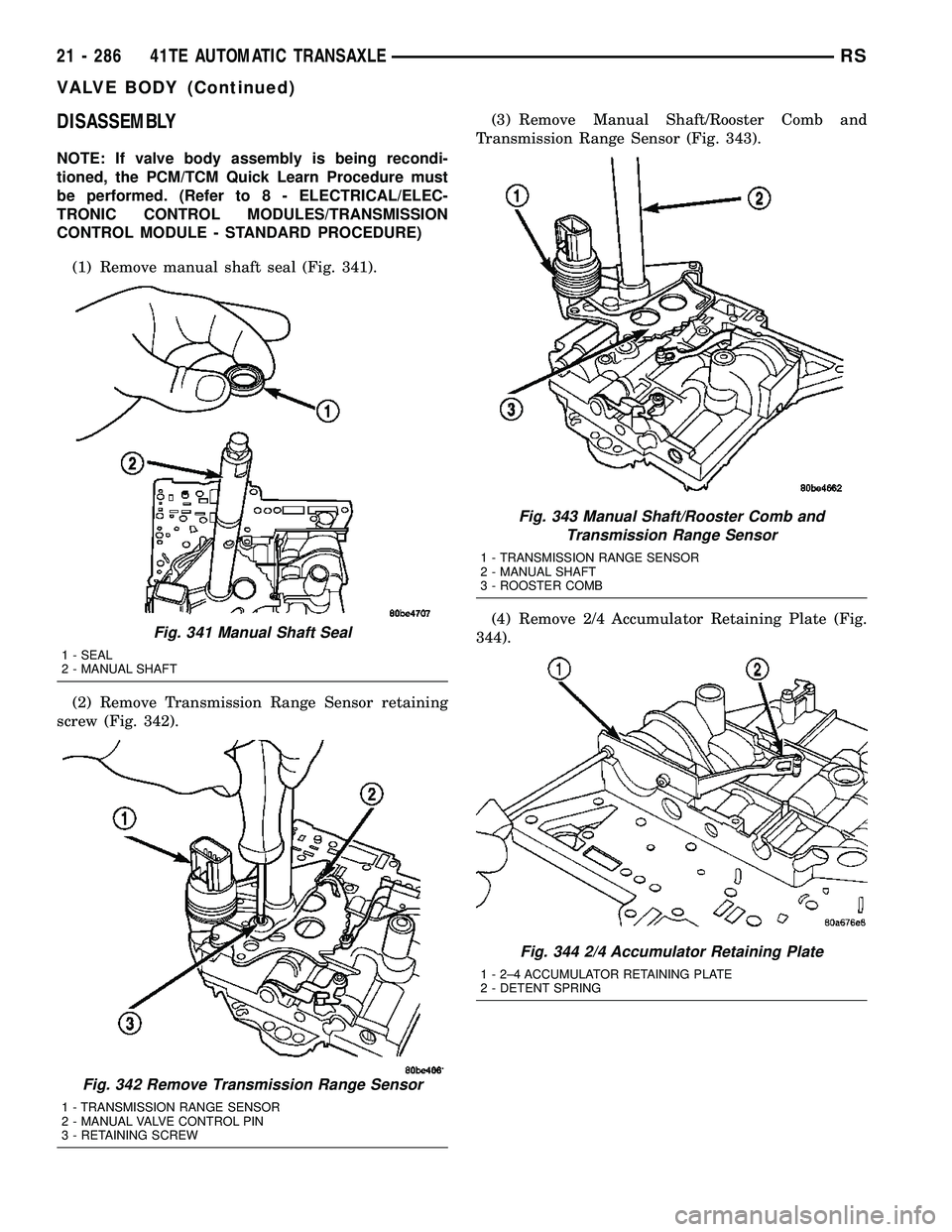
(1) Remove manual shaft seal (Fig. 341).
(2) Remove Transmission Range Sensor retaining
screw (Fig. 342).(3) Remove Manual Shaft/Rooster Comb and
Transmission Range Sensor (Fig. 343).
(4) Remove 2/4 Accumulator Retaining Plate (Fig.
344).
Fig. 341 Manual Shaft Seal
1 - SEAL
2 - MANUAL SHAFT
Fig. 342 Remove Transmission Range Sensor
1 - TRANSMISSION RANGE SENSOR
2 - MANUAL VALVE CONTROL PIN
3 - RETAINING SCREW
Fig. 343 Manual Shaft/Rooster Comb and
Transmission Range Sensor
1 - TRANSMISSION RANGE SENSOR
2 - MANUAL SHAFT
3 - ROOSTER COMB
Fig. 344 2/4 Accumulator Retaining Plate
1 - 2±4 ACCUMULATOR RETAINING PLATE
2 - DETENT SPRING
21 - 286 41TE AUTOMATIC TRANSAXLERS
VALVE BODY (Continued)
Page 1755 of 2339
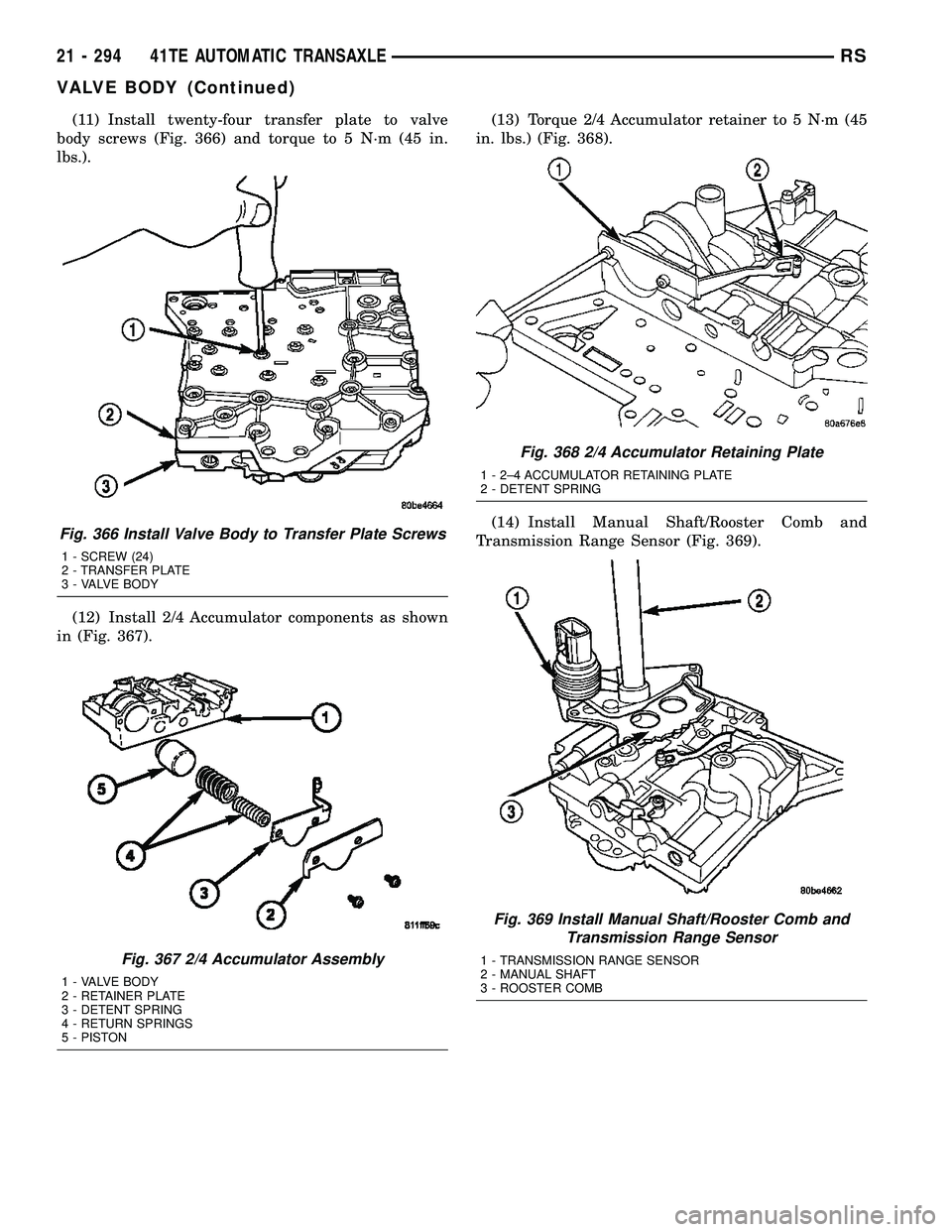
(11) Install twenty-four transfer plate to valve
body screws (Fig. 366) and torque to 5 N´m (45 in.
lbs.).
(12) Install 2/4 Accumulator components as shown
in (Fig. 367).(13) Torque 2/4 Accumulator retainer to 5 N´m (45
in. lbs.) (Fig. 368).
(14) Install Manual Shaft/Rooster Comb and
Transmission Range Sensor (Fig. 369).
Fig. 366 Install Valve Body to Transfer Plate Screws
1 - SCREW (24)
2 - TRANSFER PLATE
3 - VALVE BODY
Fig. 367 2/4 Accumulator Assembly
1 - VALVE BODY
2 - RETAINER PLATE
3 - DETENT SPRING
4 - RETURN SPRINGS
5 - PISTON
Fig. 368 2/4 Accumulator Retaining Plate
1 - 2±4 ACCUMULATOR RETAINING PLATE
2 - DETENT SPRING
Fig. 369 Install Manual Shaft/Rooster Comb and
Transmission Range Sensor
1 - TRANSMISSION RANGE SENSOR
2 - MANUAL SHAFT
3 - ROOSTER COMB
21 - 294 41TE AUTOMATIC TRANSAXLERS
VALVE BODY (Continued)
Page 1756 of 2339
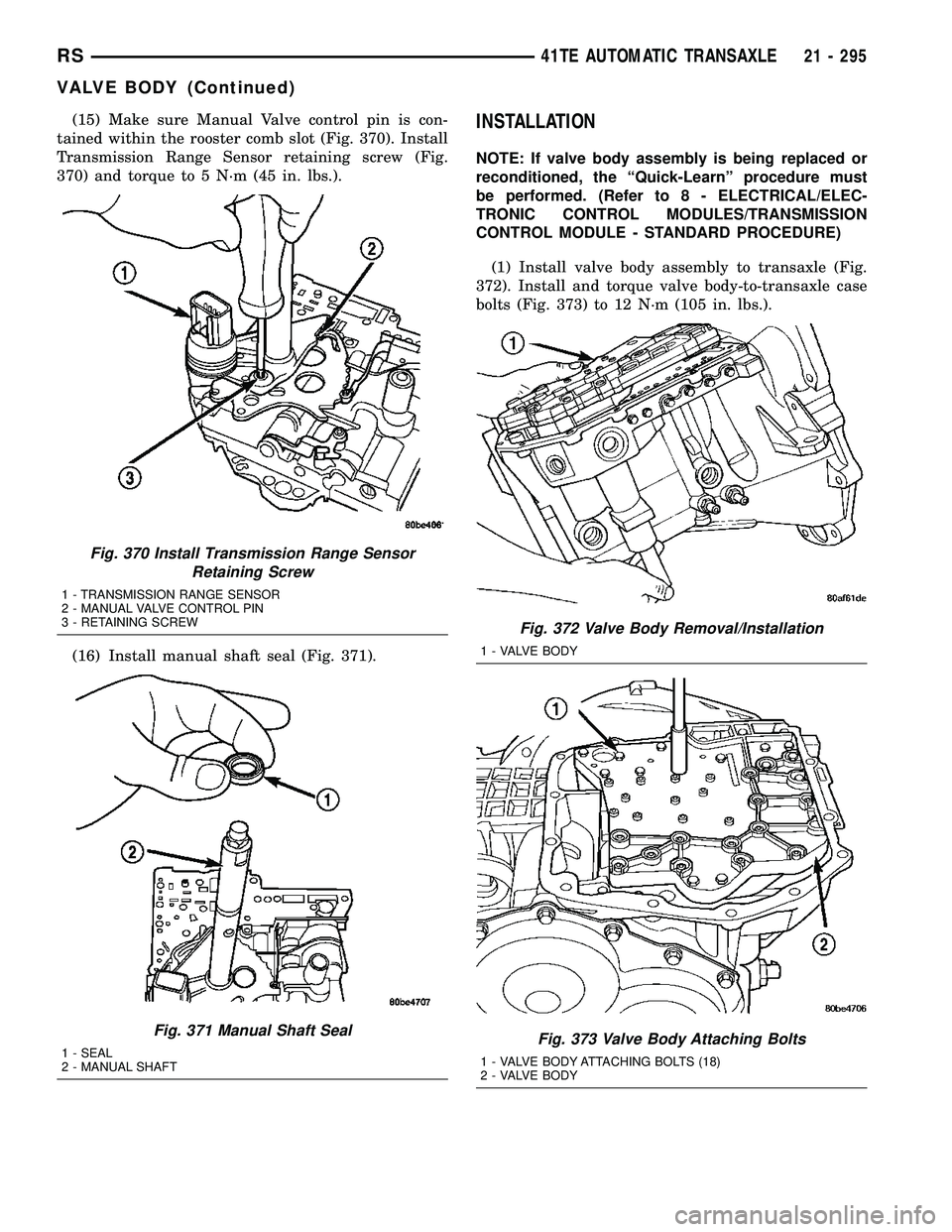
(15) Make sure Manual Valve control pin is con-
tained within the rooster comb slot (Fig. 370). Install
Transmission Range Sensor retaining screw (Fig.
370) and torque to 5 N´m (45 in. lbs.).
(16) Install manual shaft seal (Fig. 371).INSTALLATION
NOTE: If valve body assembly is being replaced or
reconditioned, the ªQuick-Learnº procedure must
be performed. (Refer to 8 - ELECTRICAL/ELEC-
TRONIC CONTROL MODULES/TRANSMISSION
CONTROL MODULE - STANDARD PROCEDURE)
(1) Install valve body assembly to transaxle (Fig.
372). Install and torque valve body-to-transaxle case
bolts (Fig. 373) to 12 N´m (105 in. lbs.).
Fig. 370 Install Transmission Range Sensor
Retaining Screw
1 - TRANSMISSION RANGE SENSOR
2 - MANUAL VALVE CONTROL PIN
3 - RETAINING SCREW
Fig. 371 Manual Shaft Seal
1 - SEAL
2 - MANUAL SHAFT
Fig. 372 Valve Body Removal/Installation
1 - VALVE BODY
Fig. 373 Valve Body Attaching Bolts
1 - VALVE BODY ATTACHING BOLTS (18)
2 - VALVE BODY
RS41TE AUTOMATIC TRANSAXLE21 - 295
VALVE BODY (Continued)
Page 1757 of 2339
(2) Install transaxle oil filter (Fig. 374). Inspect
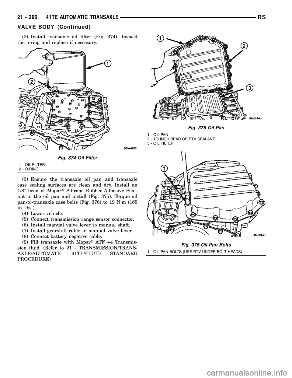
the o-ring and replace if necessary.
(3) Ensure the transaxle oil pan and transaxle
case sealing surfaces are clean and dry. Install an
1/8º bead of MopartSilicone Rubber Adhesive Seal-
ant to the oil pan and install (Fig. 375). Torque oil
pan-to-transaxle case bolts (Fig. 376) to 19 N´m (165
in. lbs.).
(4) Lower vehicle.
(5) Connect transmission range sensor connector.
(6) Install manual valve lever to manual shaft.
(7) Install gearshift cable to manual valve lever.
(8) Connect battery negative cable.
(9) Fill transaxle with MopartATF +4 Transmis-
sion fluid. (Refer to 21 - TRANSMISSION/TRANS-
AXLE/AUTOMATIC - 41TE/FLUID - STANDARD
PROCEDURE)
Fig. 374 Oil Filter
1 - OIL FILTER
2 - O-RING
Fig. 375 Oil Pan
1 - OIL PAN
2 - 1/8 INCH BEAD OF RTV SEALANT
3 - OIL FILTER
Fig. 376 Oil Pan Bolts
1 - OIL PAN BOLTS (USE RTV UNDER BOLT HEADS)
21 - 296 41TE AUTOMATIC TRANSAXLERS
VALVE BODY (Continued)
Page 1758 of 2339
TIRES/WHEELS
TABLE OF CONTENTS
page page
TIRES/WHEELS
DIAGNOSIS AND TESTING - TIRE AND
WHEEL VIBRATION.....................1
STANDARD PROCEDURE
STANDARD PROCEDURE - TIRE AND
WHEEL BALANCE......................5
STANDARD PROCEDURE - TIRE AND
WHEEL MATCH MOUNTING..............7
STANDARD PROCEDURE - TIRE AND
WHEEL ROTATION.....................7
REMOVAL
REMOVAL - TIRE AND WHEEL ASSEMBLY
(ALUMINUM WHEEL)....................8
REMOVAL - TIRE AND WHEEL ASSEMBLY
(STEEL WHEEL).......................8
INSTALLATION
INSTALLATION - TIRE AND WHEEL
ASSEMBLY (ALUMINUM WHEEL)..........8
INSTALLATION - TIRE AND WHEEL
ASSEMBLY (STEEL WHEEL)..............8
TIRE PRESSURE MONITORING
DESCRIPTION..........................9
OPERATION...........................10
SENSOR - TPM
DESCRIPTION.........................10
OPERATION...........................10
CAUTION.............................11
DIAGNOSIS AND TESTING - TIRE PRESSURE
SENSOR............................11
REMOVAL.............................11
INSTALLATION.........................11
TIRES
DESCRIPTION
DESCRIPTION - TIRE..................13
DESCRIPTION - RADIAL-PLY TIRES.......13
DESCRIPTION - REPLACEMENT TIRES....14
DESCRIPTION - SPARE TIRE
(TEMPORARY).......................14DIAGNOSIS AND TESTING
DIAGNOSIS AND TESTING - TIRE NOISE . . . 14
DIAGNOSIS AND TESTING - TIRE/VEHICLE
LEAD...............................14
DIAGNOSIS AND TESTING - TIRE WEAR
PATTERNS..........................16
DIAGNOSIS AND TESTING - TREAD WEAR
INDICATORS.........................16
STANDARD PROCEDURE
STANDARD PROCEDURE - TIRE INFLATION
PRESSURES.........................16
STANDARD PROCEDURE - TIRE
PRESSURE FOR HIGH SPEED
OPERATION.........................17
STANDARD PROCEDURE - TIRE LEAK
REPAIRING..........................17
CLEANING - TIRES.....................18
WHEELS
DESCRIPTION - WHEEL..................18
DIAGNOSIS AND TESTING - WHEEL
INSPECTION.........................19
CLEANING
WHEEL AND WHEEL TRIM CARE.........19
SPECIFICATIONS
WHEEL.............................19
WHEEL COVER
DESCRIPTION.........................19
REMOVAL.............................19
INSTALLATION.........................20
WHEEL MOUNTING STUDS - FRONT
REMOVAL.............................21
INSTALLATION.........................21
WHEEL MOUNTING STUDS - REAR
REMOVAL.............................22
INSTALLATION.........................22
TIRES/WHEELS
DIAGNOSIS AND TESTING - TIRE AND WHEEL
VIBRATION
Tire and wheel imbalance, runout and force varia-
tion can cause vehicles to exhibit steering wheel
vibration.
VISUAL INSPECTION
Visual inspection of the vehicle is recommended
prior to road testing or performing any other proce-
dure. Raise vehicle on a suitable hoist. (Refer to
LUBRICATION & MAINTENANCE/HOISTING -
STANDARD PROCEDURE)
Inspect for the following:
²Verify correct (OEM) wheel and tire, as well as
correct wheel weights. Aluminum wheels require
RSTIRES/WHEELS22-1