warning CHRYSLER CARAVAN 2005 Owner's Guide
[x] Cancel search | Manufacturer: CHRYSLER, Model Year: 2005, Model line: CARAVAN, Model: CHRYSLER CARAVAN 2005Pages: 2339, PDF Size: 59.69 MB
Page 238 of 2339
COOLANT
DESCRIPTION - ENGINE COOLANT
WARNING: ANTIFREEZE IS AN ETHYLENE GLYCOL
BASE COOLANT AND IS HARMFUL IF SWAL-
LOWED OR INHALED. IF SWALLOWED, DRINK
TWO GLASSES OF WATER AND INDUCE VOMIT-
ING. IF INHALED, MOVE TO FRESH AIR AREA.
SEEK MEDICAL ATTENTION IMMEDIATELY. DO NOT
STORE IN OPEN OR UNMARKED CONTAINERS.
WASH SKIN AND CLOTHING THOROUGHLY AFTER
COMING IN CONTACT WITH ETHYLENE GLYCOL.
KEEP OUT OF REACH OF CHILDREN. DISPOSE OF
GLYCOL BASE COOLANT PROPERLY, CONTACT
YOUR DEALER OR GOVERNMENT AGENCY FOR
LOCATION OF COLLECTION CENTER IN YOUR
AREA. DO NOT OPEN A COOLING SYSTEM WHEN
THE ENGINE IS AT OPERATING TEMPERATURE OR
HOT UNDER PRESSURE, PERSONAL INJURY CAN
RESULT. AVOID RADIATOR COOLING FAN WHEN
ENGINE COMPARTMENT RELATED SERVICE IS
PERFORMED, PERSONAL INJURY CAN RESULT.
CAUTION: Use of Propylene Glycol based coolants
is not recommended, as they provide less freeze
protection and less boiling protection.
The cooling system is designed around the coolant.
The coolant must accept heat from engine metal, in
the cylinder head area near the exhaust valves and
engine block. Then coolant carries the heat to the
radiator where the tube/fin radiator can transfer the
heat to the air.
The use of aluminum cylinder blocks, cylinder
heads, and water pumps requires special corrosion
protection. MopartAntifreeze/Coolant, 5
Year/100,000 Mile Formula (MS-9769), or the equiva-
lent ethylene glycol base coolant with hybrid organic
corrosion inhibitors (called HOAT, for Hybrid Organic
Additive Technology) is recommended. This coolant
offers the best engine cooling without corrosion when
mixed with 50% Ethylene Glycol and 50% distilled
water to obtain a freeze point of -37ÉC (-35ÉF). If it
loses color or becomes contaminated, drain, flush,
and replace with fresh properly mixed coolant solu-
tion.
The green coolantMUST NOT BE MIXEDwith
the orange or magenta coolants. When replacing cool-
ant the complete system flush must be performed
before using the replacement coolant.CAUTION: MoparTAntifreeze/Coolant, 5
Year/100,000 Mile Formula (MS-9769) may not be
mixed with any other type of antifreeze. Doing so
will reduce the corrosion protection and may result
in premature water pump seal failure. If non-HOAT
coolant is introduced into the cooling system in an
emergency, it should be replaced with the specified
coolant as soon as possible.
DIAGNOSIS AND TESTING - COOLANT
CONCENTRATION TESTING
Coolant concentration should be checked when any
additional coolant was added to system or after a
coolant drain, flush and refill. The coolant mixture
offers optimum engine cooling and protection against
corrosion when mixed to a freeze point of -37ÉC
(-34ÉF) to -46ÉC (-50ÉF). The use of a hydrometer or a
refractometer can be used to test coolant concentra-
tion.
A hydrometer will test the amount of glycol in a
mixture by measuring the specific gravity of the mix-
ture. The higher the concentration of ethylene glycol,
the larger the number of balls that will float, and
higher the freeze protection (up to a maximum of
60% by volume glycol).
A refractometer (Special Tool 8286)(Refer to 7 -
COOLING - SPECIAL TOOLS) will test the amount
of glycol in a coolant mixture by measuring the
amount a beam of light bends as it passes through
the fluid.
Some coolant manufactures use other types of gly-
cols into their coolant formulations. Propylene glycol
is the most common new coolant. However, propylene
glycol based coolants do not provide the same freez-
ing protection and corrosion protection and is not rec-
ommended.
CAUTION: Do not mix types of coolantÐcorrosion
protection will be severely reduced.
STANDARD PROCEDURE - COOLANT SERVICE
For engine coolant recommended service schedule,
(Refer to LUBRICATION & MAINTENANCE/MAIN-
TENANCE SCHEDULES - DESCRIPTION).
RSENGINE7-19
Page 240 of 2339

DIAGNOSIS AND TESTING - ENGINE BLOCK
HEATER TESTING
If unit does not operate, trouble can be in either
the power cord or the heater element. Test power
cord for continuity with a 110-volt voltmeter or 110-
volt test light; test heater element continuity with an
ohmmeter or 12-volt test light.
REMOVAL
(1) Drain coolant from radiator and cylinder block.
(Refer to 7 - COOLING - STANDARD PROCEDURE)
(2) Disconnect the power cord plug from heater.
(3) Loosen screw in center of heater. Remove the
heater assembly.
INSTALLATION
(1) Clean block core hole and heater seat.
(2) Insert heater assembly with element loop posi-
tionedupward.
(3) With heater seated, tighten center screw
securely to assure a positive seal.
(4) Install power cord plug to heater.
(5) Fill cooling system with coolant to the proper
level. (Refer to 7 - COOLING - STANDARD PROCE-
DURE)
ENGINE COOLANT
TEMPERATURE SENSOR - 2.4L
DESCRIPTION
The engine coolant temperature sensor threads
into the top of the thermostat housing (Fig. 3). New
sensors have sealant applied to the threads.
REMOVAL
WARNING: HOT, PRESSURIZED COOLANT CAN
CAUSE INJURY BY SCALDING. COOLING SYSTEM
MUST BE PARTIALLY DRAINED BEFORE REMOV-
ING THE COOLANT TEMPERATURE SENSOR.
(1) Drain the cooling system below thermostat
level. (Refer to 7 - COOLING - STANDARD PROCE-
DURE)
(2) Disconnect coolant temperature sensor electri-
cal connector.
(3) Remove coolant temperature sensor (Fig. 3).
INSTALLATION
(1) Install coolant temperature sensor (Fig. 3).
Tighten sensor to 7 N´m (60 in. lbs.).
(2) Connect electrical connector to sensor.
(3) Fill cooling system. (Refer to 7 - COOLING -
STANDARD PROCEDURE)
ENGINE COOLANT
TEMPERATURE SENSOR -
3.3/3.8L
DESCRIPTION
The engine coolant temperature sensor threads
into a coolant passage on lower intake manifold near
the thermostat (Fig. 6). New sensors have sealant
applied to the threads.
REMOVAL
WARNING: HOT, PRESSURIZED COOLANT CAN
CAUSE INJURY BY SCALDING. COOLING SYSTEM
MUST BE PARTIALLY DRAINED BEFORE REMOV-
ING THE COOLANT TEMPERATURE SENSOR.
Fig. 3 Engine Coolant Temperature Sensor - 2.4L
1 - MAP SENSOR
2 - COOLANT TEMPERATURE SENSOR
RSENGINE7-21
ENGINE BLOCK HEATER (Continued)
Page 245 of 2339

RADIATOR
REMOVAL
(1) Disconnect negative cable from battery.
(2) Remove radiator upper crossmember support.
(Refer to 23 - BODY/EXTERIOR/GRILLE OPENING
REINFORCEMENT - REMOVAL)
WARNING: DO NOT REMOVE THE CYLINDER
BLOCK PLUG OR THE RADIATOR DRAINCOCK
WITH THE SYSTEM HOT AND UNDER PRESSURE
BECAUSE SERIOUS BURNS FROM COOLANT CAN
OCCUR.
(3) Drain the cooling system. (Refer to 7 - COOL-
ING - STANDARD PROCEDURE)
(4) Remove the radiator fans. (Refer to 7 - COOL-
ING/ENGINE/RADIATOR FAN - REMOVAL)
(5) Disconnect coolant reserve/recovery hose.
(6) Remove vapor purge solenoid from mounting
bracket.
(7) Disconnect upper and lower hoses from the
radiator (Fig. 13) or (Fig. 14).
(8) Lift the A/C condenser straight up to disengage
the lower A/C condenser mounting brackets from the
radiator. (Fig. 15). Separate the condenser from the
radiator by lifting upward to disengage from lower
mounts (Fig. 15). Allow the condenser to rest in front
of radiator.(9) Radiator can now be lifted free from engine
compartment.Care should be taken not to dam-
age radiator cooling fins or water tubes during
removal.
Fig. 13 Radiator Hoses to Radiator - 2.4L
1 - UPPER HOSE
2 - LOWER HOSE
3 - HOSE SUPPORT CLIP
Fig. 14 Radiator Hoses to Radiator - 3.3/3.8L
1 - UPPER HOSE
2 - LOWER HOSE
Fig. 15 A/C Condenser ± 2.4L/3.3L/3.8L Engines
1 - A/C CONDENSER
2 - AUTO TRANS COOLER TAPPING BLOCK
3 - UPPER CONDENSER MOUNTING BRACKET (2)
4 - RADIATOR
5 - LOWER CONDENSER MOUNTING BRACKET (2)
7 - 26 ENGINERS
Page 247 of 2339
DIAGNOSIS AND TESTING
DIAGNOSIS AND TESTING - COOLING SYSTEM
PRESSURE CAP TESTING
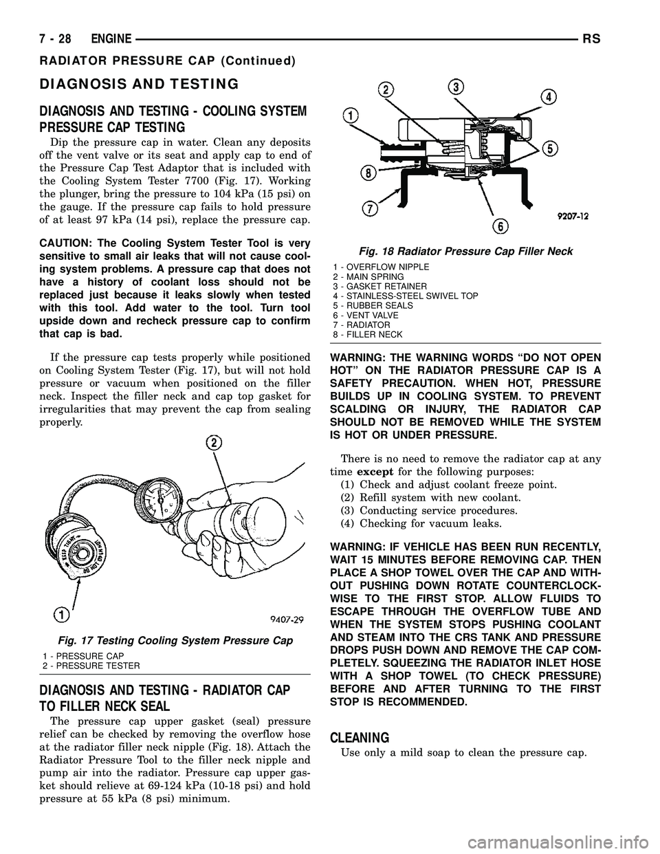
Dip the pressure cap in water. Clean any deposits
off the vent valve or its seat and apply cap to end of
the Pressure Cap Test Adaptor that is included with
the Cooling System Tester 7700 (Fig. 17). Working
the plunger, bring the pressure to 104 kPa (15 psi) on
the gauge. If the pressure cap fails to hold pressure
of at least 97 kPa (14 psi), replace the pressure cap.
CAUTION: The Cooling System Tester Tool is very
sensitive to small air leaks that will not cause cool-
ing system problems. A pressure cap that does not
have a history of coolant loss should not be
replaced just because it leaks slowly when tested
with this tool. Add water to the tool. Turn tool
upside down and recheck pressure cap to confirm
that cap is bad.
If the pressure cap tests properly while positioned
on Cooling System Tester (Fig. 17), but will not hold
pressure or vacuum when positioned on the filler
neck. Inspect the filler neck and cap top gasket for
irregularities that may prevent the cap from sealing
properly.
DIAGNOSIS AND TESTING - RADIATOR CAP
TO FILLER NECK SEAL
The pressure cap upper gasket (seal) pressure
relief can be checked by removing the overflow hose
at the radiator filler neck nipple (Fig. 18). Attach the
Radiator Pressure Tool to the filler neck nipple and
pump air into the radiator. Pressure cap upper gas-
ket should relieve at 69-124 kPa (10-18 psi) and hold
pressure at 55 kPa (8 psi) minimum.WARNING: THE WARNING WORDS ªDO NOT OPEN
HOTº ON THE RADIATOR PRESSURE CAP IS A
SAFETY PRECAUTION. WHEN HOT, PRESSURE
BUILDS UP IN COOLING SYSTEM. TO PREVENT
SCALDING OR INJURY, THE RADIATOR CAP
SHOULD NOT BE REMOVED WHILE THE SYSTEM
IS HOT OR UNDER PRESSURE.
There is no need to remove the radiator cap at any
timeexceptfor the following purposes:
(1) Check and adjust coolant freeze point.
(2) Refill system with new coolant.
(3) Conducting service procedures.
(4) Checking for vacuum leaks.
WARNING: IF VEHICLE HAS BEEN RUN RECENTLY,
WAIT 15 MINUTES BEFORE REMOVING CAP. THEN
PLACE A SHOP TOWEL OVER THE CAP AND WITH-
OUT PUSHING DOWN ROTATE COUNTERCLOCK-
WISE TO THE FIRST STOP. ALLOW FLUIDS TO
ESCAPE THROUGH THE OVERFLOW TUBE AND
WHEN THE SYSTEM STOPS PUSHING COOLANT
AND STEAM INTO THE CRS TANK AND PRESSURE
DROPS PUSH DOWN AND REMOVE THE CAP COM-
PLETELY. SQUEEZING THE RADIATOR INLET HOSE
WITH A SHOP TOWEL (TO CHECK PRESSURE)
BEFORE AND AFTER TURNING TO THE FIRST
STOP IS RECOMMENDED.
CLEANING
Use only a mild soap to clean the pressure cap.
Fig. 17 Testing Cooling System Pressure Cap
1 - PRESSURE CAP
2 - PRESSURE TESTER
Fig. 18 Radiator Pressure Cap Filler Neck
1 - OVERFLOW NIPPLE
2 - MAIN SPRING
3 - GASKET RETAINER
4 - STAINLESS-STEEL SWIVEL TOP
5 - RUBBER SEALS
6 - VENT VALVE
7 - RADIATOR
8 - FILLER NECK
7 - 28 ENGINERS
RADIATOR PRESSURE CAP (Continued)
Page 261 of 2339
mation. For diagnosis of these electronic modules or
of the data bus network, the use of a DRB IIItscan
tool and the proper Diagnostic Procedures informa-
tion is recommended.
DIAGNOSIS AND TESTING
AUDIO/VIDEO
Any diagnosis of the Audio system should
begin with the use of the DRB IIItdiagnostic
tool. For information on the use of the DRBIIIt, refer to the appropriate Diagnostic Service
information.
Refer to the appropriate wiring information.
WARNING: ON VEHICLES EQUIPPED WITH AIR-
BAGS, REFER TO ELECTRICAL, RESTRAINTS
BEFORE ATTEMPTING ANY STEERING WHEEL,
STEERING COLUMN, OR INSTRUMENT PANEL
COMPONENT DIAGNOSIS OR SERVICE. FAILURE
TO TAKE THE PROPER PRECAUTIONS COULD
RESULT IN ACCIDENTAL AIRBAG DEPLOYMENT
AND POSSIBLE PERSONAL INJURY.
AUDIO SYSTEM DIAGNOSIS
CONDITION POSSIBLE CAUSE CORRECTION
NO AUDIO. 1. FUSE INOPERATIVE. 1. CHECK RADIO FUSES IN FUSE BLOCK MODULE.
REPLACE FUSES, IF REQUIRED.
2. RADIO CONNECTOR
DAMAGED.2. CHECK FOR LOOSE OR CORRODED RADIO CONNECTOR.
REPAIR, IF REQUIRED.
3. WIRING DAMAGED. 3. CHECK FOR BATTERY VOLTAGE AT RADIO CONNECTOR.
REPAIR WIRING, IF REQUIRED.
4. GROUND DAMAGED. 4. CHECK FOR CONTINUITY BETWEEN RADIO CHASSIS AND
A KNOWN GOOD GROUND. THERE SHOULD BE
CONTINUITY. REPAIR GROUND, IF REQUIRED.
5. RADIO
INOPERATIVE.5. USING A SCAN TOOL, CHECK FOR TROUBLE CODES IN
THE AUDIO SYSTEM.
6. SPEAKERS
INOPERATIVE6. REFER TO SPEAKER DIAGNOSIS.
NO DISPLAY. 1. FUSE INOPERATIVE. 1. CHECK RADIO FUSES IN FUSE BLOCK MODULE.
REPLACE FUSES, IF REQUIRED.
2. RADIO CONNECTOR
DAMAGED.2. CHECK FOR LOOSE OR CORRODED RADIO CONNECTOR.
REPAIR, IF REQUIRED.
3. WIRING DAMAGED. 3. CHECK FOR BATTERY VOLTAGE AT RADIO CONNECTOR.
REPAIR WIRING, IF REQUIRED.
4. GROUND DAMAGED. 4. CHECK FOR CONTINUITY BETWEEN RADIO CHASSIS AND
A KNOWN GOOD GROUND. THERE SHOULD BE
CONTINUITY. REPAIR GROUND, IF REQUIRED.
5. RADIO
INOPERATIVE.5. USING A SCAN TOOL, CHECK FOR TROUBLE CODES IN
THE AUDIO SYSTEM.
NO MEMORY. 1. FUSE INOPERATIVE. 1. CHECK IGNITION-OFF DRAW FUSE. REPLACE FUSE, IF
REQUIRED.
2. RADIO CONNECTOR
DAMAGED.2. CHECK FOR LOOSE OR CORRODED RADIO CONNECTOR.
REPAIR, IF REQUIRED.
3. WIRING DAMAGED. 3. CHECK FOR BATTERY VOLTAGE AT RADIO CONNECTOR.
REPAIR WIRING, IF REQUIRED.
8A - 2 AUDIO/VIDEORS
AUDIO/VIDEO (Continued)
Page 267 of 2339
DIAGNOSIS AND TESTING
ANTENNA BODY AND CABLE
WARNING: ON VEHICLES EQUIPPED WITH AIR-
BAGS, REFER TO ELECTRICAL, RESTRAINTS
BEFORE ATTEMPTING ANY STEERING WHEEL,
STEERING COLUMN, OR INSTRUMENT PANEL
COMPONENT DIAGNOSIS OR SERVICE. FAILURE
TO TAKE THE PROPER PRECAUTIONS COULD
RESULT IN ACCIDENTAL AIRBAG DEPLOYMENT
AND POSSIBLE PERSONAL INJURY.
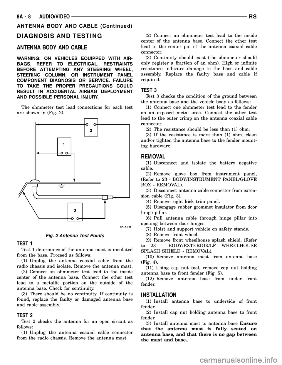
The ohmmeter test lead connections for each test
are shown in (Fig. 2).
TEST 1
Test 1 determines of the antenna mast is insulated
from the base. Proceed as follows:
(1) Unplug the antenna coaxial cable from the
radio chassis and isolate. Remove the antenna mast.
(2) Connect an ohmmeter test lead to the inside
center of the antenna base. Connect the other test
lead to a metallic portion on the outside of the
antenna base. Check for continuity.
(3) There should be no continuity. If continuity is
found, replace the faulty or damaged antenna base
and cable assembly.
TEST 2
Test 2 checks the antenna for an open circuit as
follows:
(1) Unplug the antenna coaxial cable connector
from the radio chassis. Remove the antenna mast.(2) Connect an ohmmeter test lead to the inside
center of the antenna base. Connect the other test
lead to the center pin of the antenna coaxial cable
connector.
(3) Continuity should exist (the ohmmeter should
only register a fraction of an ohm). High or infinite
resistance indicates damage to the base and cable
assembly. Replace the faulty base and cable if
required.
TEST 3
Test 3 checks the condition of the ground between
the antenna base and the vehicle body as follows:
(1) Connect one ohmmeter test lead to the fender
on an exposed metal area. Connect the other test
lead to the outer crimp on the antenna coaxial cable
connector.
(2) The resistance should be less than (1) ohm.
(3) If the resistance is more than (1) ohm, clean
and/or tighten the antenna base to the fender mount-
ing hardware.
REMOVAL
(1) Disconnect and isolate the battery negative
cable.
(2) Remove glove box from instrument panel,
(Refer to 23 - BODY/INSTRUMENT PANEL/GLOVE
BOX - REMOVAL).
(3) Disconnect antenna cable connector from exten-
sion cable (Fig. 3).
(4) Remove right kick trim panel.
(5) Disengage rubber grommet insulator from door
hinge pillar.
(6) Pull antenna cable through hinge pillar into
opening between door hinges.
(7) Hoist and support vehicle on safety stands.
(8) Remove front wheel.
(9) Remove front wheelhouse splash shield. (Refer
to 23 - BODY/EXTERIOR/LF WHEELHOUSE
SPLASH SHIELD - REMOVAL).
(10) Remove antenna mast from antenna base
(Fig. 4).
(11) Using cap nut tool, remove cap nut holding
antenna base to front fender (Fig. 5).
(12) Remove antenna base from under front
fender.
INSTALLATION
(1) Install antenna base to underside of front
fender.
(2) Install cap nut holding antenna base to front
fender.
(3) Install antenna mast to antenna baseEnsure
that the antenna mast is fully seated on
antenna base, and that there is no gap between
the mast and base..
Fig. 2 Antenna Test Points
8A - 8 AUDIO/VIDEORS
ANTENNA BODY AND CABLE (Continued)
Page 271 of 2339
(3) Install screws holding CD changer.
(4) Reconnect the battery negative cable.
DVD PLAYER
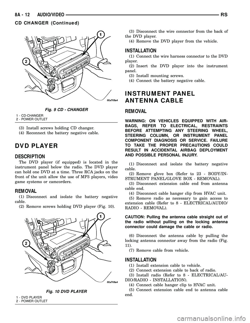
DESCRIPTION
The DVD player (if equipped) is located in the
instrument panel below the radio. The DVD player
can hold one DVD at a time. Three RCA jacks on the
front of the unit allow the use of MP3 players, video
game systems or camcorders.
REMOVAL
(1) Disconnect and isolate the battery negative
cable.
(2) Remove screws holding DVD player (Fig. 10).(3) Disconnect the wire connector from the back of
the DVD player.
(4) Remove the DVD player from the vehicle.
INSTALLATION
(1) Connect the wire harness connector to the DVD
player.
(2) Insert the DVD player into the instrument
panel.
(3) Install mounting screws.
(4) Connect the battery negative cable.
INSTRUMENT PANEL
ANTENNA CABLE
REMOVAL
WARNING: ON VEHICLES EQUIPPED WITH AIR-
BAGS, REFER TO ELECTRICAL, RESTRAINTS
BEFORE ATTEMPTING ANY STEERING WHEEL,
STEERING COLUMN, OR INSTRUMENT PANEL
COMPONENT DIAGNOSIS OR SERVICE. FAILURE
TO TAKE THE PROPER PRECAUTIONS COULD
RESULT IN ACCIDENTAL AIRBAG DEPLOYMENT
AND POSSIBLE PERSONAL INJURY.
(1) Disconnect and isolate the battery negative
cable.
(2) Remove glove box (Refer to 23 - BODY/IN-
STRUMENT PANEL/GLOVE BOX - REMOVAL).
(3) Disconnect extension cable end from antenna
cable end.
(4) Disconnect cable hanger clip from HVAC unit.
(5) Remove radio as necessary to gain access to
extension cable (Refer to 8 - ELECTRICAL/AUDIO/
RADIO - REMOVAL).
CAUTION: Pulling the antenna cable straight out of
the radio without pulling on the locking antenna
connector could damage the cable or radio.
(6) Disconnect the antenna cable by pulling the
locking antenna connector away from the radio (Fig.
11).
(7) Remove cable from vehicle.
INSTALLATION
(1) Install extension cable to vehicle.
(2) Connect extension cable to back of radio.
(3) Install radio (Refer to 8 - ELECTRICAL/AU-
DIO/RADIO - INSTALLATION).
(4) Connect cable hanger clip to HVAC unit.
(5) Connect extension cable end to antenna cable
end.
Fig. 9 CD - CHANGER
1 - CD-CHANGER
2 - POWER OUTLET
Fig. 10 DVD PLAYER
1 - DVD PLAYER
2 - POWER OUTLET
8A - 12 AUDIO/VIDEORS
CD CHANGER (Continued)
Page 273 of 2339
OPERATION
The radio receiver operates on ignition switched
battery current that is available only when the igni-
tion switch is in the On or Accessory/Accessory Delay
positions. The electronic digital clock function of the
radio operates on fused battery current supplied
through the IOD fuse, regardless of the ignition
switch position.
For complete circuit diagrams, refer to the appro-
priate wiring information.
DIAGNOSIS AND TESTING
RADIO
WARNING: ON VEHICLES EQUIPPED WITH AIR-
BAGS, REFER TO ELECTRICAL, RESTRAINTS
BEFORE ATTEMPTING ANY STEERING WHEEL,
STEERING COLUMN, OR INSTRUMENT PANEL
COMPONENT DIAGNOSIS OR SERVICE. FAILURE
TO TAKE THE PROPER PRECAUTIONS COULD
RESULT IN ACCIDENTAL AIRBAG DEPLOYMENT
AND POSSIBLE PERSONAL INJURY.
Any diagnosis of the Audio system should
begin with the use of the DRB IIItdiagnostic
tool. For information on the use of the DRB
IIIt, refer to the appropriate Diagnostic Service
Manual.
Refer to the appropriate wiring information.
If the vehicle is equipped with remote radio
switches located on the back of the steering wheel
spokes, and the problem being diagnosed is related to
one of the symptoms listed below, be certain to check
the remote radio switches and circuits as described
in this group, prior to attempting radio diagnosis or
repair.
²Stations changing with no remote radio switch
input
²Radio memory presets not working properly
²Volume changes with no remote radio switch
input
²Remote radio switch buttons taking on other
functions
²CD player skipping tracks
²Remote radio switch inoperative.
CAUTION: The speaker output of the radio is a
ªfloating groundº system. Do not allow any speaker
lead to short to ground, as damage to the radio
may result.
(1) Check the fuse(s) in the junction block and the
Integrated Power Module (IPM). If OK, go to Step 2.
If not OK, repair the shorted circuit or component as
required and replace the faulty fuse(s).(2) Check for battery voltage at the fuse in the
(IPM). If OK, go to Step 3. If not OK, repair the open
circuit to the battery as required.
(3) Turn the ignition switch to the ON position.
Check for battery voltage at the fuse in the junction
block. If OK, go to Step 4. If not OK, repair the open
circuit to the ignition switch as required.
(4) Turn the ignition switch to the OFF position.
Remove the radio, but do not unplug the wire har-
ness connectors. Check for continuity between the
radio chassis and a good ground. There should be
continuity. If OK, go to Step 5. If not OK, repair the
open radio chassis ground circuit as required.
(5) Connect the battery negative cable. Turn the
ignition switch to the ON position. Check for battery
voltage at the fused ignition switch output circuit
cavity of the radio wire harness connector. If OK, go
to Step 6. If not OK, repair the open circuit as
required.
(6) Turn the ignition switch to the OFF position.
Check for battery voltage at the fused B(+) circuit
cavity of the radio wire harness connector. If OK,
replace the faulty radio. If not OK, repair the open
circuit to the Ignition-Off Draw (IOD) fuse as
required.
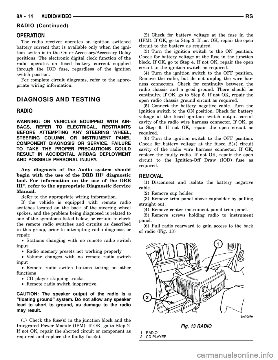
REMOVAL
(1) Disconnect and isolate the battery negative
cable.
(2) Remove cup holder.
(3) Remove trim panel above cupholder by pulling
straight out.
(4) Remove center instrument panel trim panel.
(5) Remove screws holding radio to instrument
panel.
(6) Pull radio rearward to gain access to the back
of radio (Fig. 13).
Fig. 13 RADIO
1 - RADIO
2 - CD-PLAYER
8A - 14 AUDIO/VIDEORS
RADIO (Continued)
Page 275 of 2339
REMOTE SWITCHES
DESCRIPTION
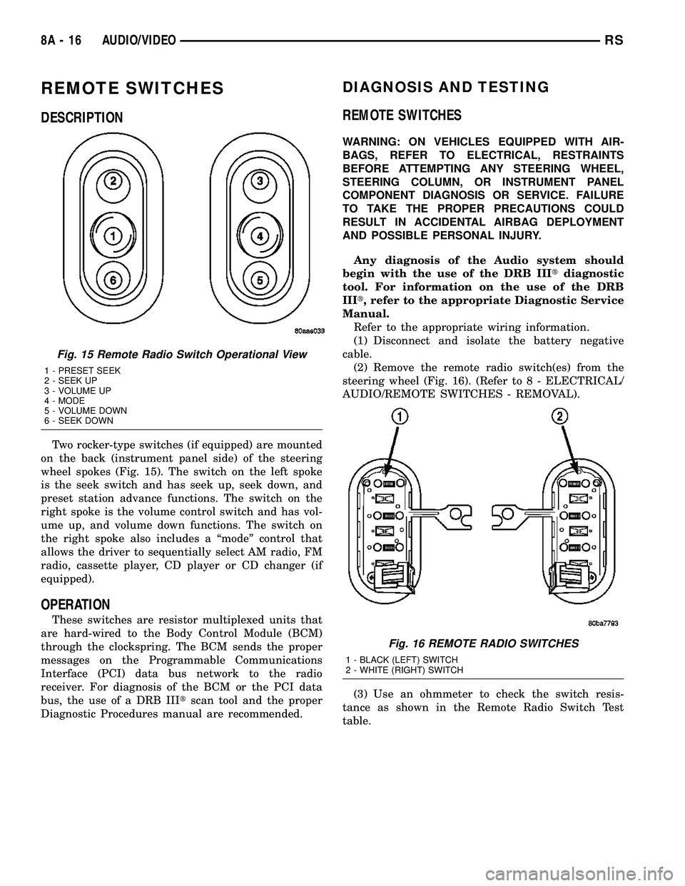
Two rocker-type switches (if equipped) are mounted
on the back (instrument panel side) of the steering
wheel spokes (Fig. 15). The switch on the left spoke
is the seek switch and has seek up, seek down, and
preset station advance functions. The switch on the
right spoke is the volume control switch and has vol-
ume up, and volume down functions. The switch on
the right spoke also includes a ªmodeº control that
allows the driver to sequentially select AM radio, FM
radio, cassette player, CD player or CD changer (if
equipped).
OPERATION
These switches are resistor multiplexed units that
are hard-wired to the Body Control Module (BCM)
through the clockspring. The BCM sends the proper
messages on the Programmable Communications
Interface (PCI) data bus network to the radio
receiver. For diagnosis of the BCM or the PCI data
bus, the use of a DRB IIItscan tool and the proper
Diagnostic Procedures manual are recommended.
DIAGNOSIS AND TESTING
REMOTE SWITCHES
WARNING: ON VEHICLES EQUIPPED WITH AIR-
BAGS, REFER TO ELECTRICAL, RESTRAINTS
BEFORE ATTEMPTING ANY STEERING WHEEL,
STEERING COLUMN, OR INSTRUMENT PANEL
COMPONENT DIAGNOSIS OR SERVICE. FAILURE
TO TAKE THE PROPER PRECAUTIONS COULD
RESULT IN ACCIDENTAL AIRBAG DEPLOYMENT
AND POSSIBLE PERSONAL INJURY.
Any diagnosis of the Audio system should
begin with the use of the DRB IIItdiagnostic
tool. For information on the use of the DRB
IIIt, refer to the appropriate Diagnostic Service
Manual.
Refer to the appropriate wiring information.
(1) Disconnect and isolate the battery negative
cable.
(2) Remove the remote radio switch(es) from the
steering wheel (Fig. 16). (Refer to 8 - ELECTRICAL/
AUDIO/REMOTE SWITCHES - REMOVAL).
(3) Use an ohmmeter to check the switch resis-
tance as shown in the Remote Radio Switch Test
table.
Fig. 15 Remote Radio Switch Operational View
1 - PRESET SEEK
2 - SEEK UP
3 - VOLUME UP
4 - MODE
5 - VOLUME DOWN
6 - SEEK DOWN
Fig. 16 REMOTE RADIO SWITCHES
1 - BLACK (LEFT) SWITCH
2 - WHITE (RIGHT) SWITCH
8A - 16 AUDIO/VIDEORS
Page 276 of 2339

REMOTE RADIO SWITCH TEST
Switch Switch Position Resistance
Right
(White)Volume Up 1.210 Kilohms
Right
(White)Volume Down 3.010 Kilohms
Right
(White)Mode Advance 0.0511 Kilohms
Left
(Black)Seek Up 0.261 Kilohms
Left
(Black)Seek Down 0.681 Kilohms
Left
(Black)Pre-Set Station
Advance0.162 Kilohms
NOTE: The right remote radio switch back is white
in color. The left switch back is black in color. The
right/left remote radio switch orientation is with the
steering wheel installed, and driver in drivers seat.
(4) If the switch resistance checks OK, go to Step
5. If not OK, replace the faulty switch.
(5) Check for continuity between the ground cir-
cuit cavity of the switch wire harness connector and
a good ground. There should be continuity. If OK, go
to Step 6. If not OK, repair the open circuit as
required.
(6) Unplug the 24-way white wire harness connec-
tor from the Body Control Module (BCM). Check for
continuity between the radio control circuit cavity of
the remote radio switch wire harness connector and a
good ground. There should be no continuity. If OK, go
to Step 7. If not OK, repair the short circuit as
required.
(7) Check for continuity between the radio control
circuit cavities of the remote radio switch wire har-
ness connector and the BCM wire harness connector.
There should be continuity. If OK, refer to the proper
Diagnostic Procedures manual to test the BCM and
the PCI data bus. If not OK, repair the open circuit
as required.
REMOVAL
WARNING: ON VEHICLES EQUIPPED WITH AIR-
BAGS, REFER TO ELECTRICAL, RESTRAINTS
BEFORE ATTEMPTING ANY STEERING WHEEL,
STEERING COLUMN, OR INSTRUMENT PANEL
COMPONENT DIAGNOSIS OR SERVICE. FAILURE
TO TAKE THE PROPER PRECAUTIONS COULD
RESULT IN ACCIDENTAL AIRBAG DEPLOYMENT
AND POSSIBLE PERSONAL INJURY.(1) Disconnect and isolate the battery negative
cable.
(2) Remove the driver side airbag (Refer to 8 -
ELECTRICAL/RESTRAINTS/DRIVER AIRBAG -
REMOVAL).
(3) Remove the steering wheel (Refer to 19 -
STEERING/COLUMN/STEERING WHEEL -
REMOVAL).
(4) Unplug the wire harness connector from the
remote radio switch (es).
(5) Remove three screws securing steering wheel
rear cover.
(6) Remove the remote radio switch from the steer-
ing wheel by depressing tabs on each side of each
switch.
NOTE: The right remote radio switch back is white
in color. The left switch back is black in color. The
right/left remote radio switch orientation is with the
steering wheel installed, and driver in drivers seat.
INSTALLATION
WARNING: ON VEHICLES EQUIPPED WITH AIR-
BAGS, REFER TO ELECTRICAL, RESTRAINTS
BEFORE ATTEMPTING ANY STEERING WHEEL,
STEERING COLUMN, OR INSTRUMENT PANEL
COMPONENT DIAGNOSIS OR SERVICE. FAILURE
TO TAKE THE PROPER PRECAUTIONS COULD
RESULT IN ACCIDENTAL AIRBAG DEPLOYMENT
AND POSSIBLE PERSONAL INJURY.
(1) Install remote radio switch to the steering
wheel.
(2) Install three screws securing steering wheel
rear cover.
(3) Connect the wire harness to the remote radio
switch.
(4) Install the steering wheel (Refer to 19 -
STEERING/COLUMN/STEERING WHEEL -
INSTALLATION).
(5) Install the driver side airbag (Refer to 8 -
ELECTRICAL/RESTRAINTS/DRIVER AIRBAG -
INSTALLATION).
(6) Connect the battery negative cable.
RSAUDIO/VIDEO8A-17
REMOTE SWITCHES (Continued)