CLUSTER CHRYSLER CARAVAN 2005 Workshop Manual
[x] Cancel search | Manufacturer: CHRYSLER, Model Year: 2005, Model line: CARAVAN, Model: CHRYSLER CARAVAN 2005Pages: 2339, PDF Size: 59.69 MB
Page 1321 of 2339
INSTALLATION
(1) Clean relief valve, spring and bore.
NOTE: Lubricate relief valve with clean engine oil
before installing.
(2) Install relief valve and spring into housing.
(3) Install new retainer cap until flush with seal-
ing surface.
(4) Install oil pan (Refer to 9 - ENGINE/LUBRI-
CATION/OIL PAN - INSTALLATION).
(5) Fill crankcase with proper oil to correct level.
OIL PRESSURE SWITCH
DESCRIPTION
The engine oil pressure switch is located on the
lower left front side of the engine. It screws into the
oil filter adapter. The normally closed switch provides
an input through a single wire to the low pressure
indicator light on the instrument cluster.
OPERATION
The oil pressure switch provides a ground for the
instrument cluster low oil pressure indicator light.
The switch receives oil pressure input from the
engine main oil gallery. When engine oil pressure is
greater than 27.5 Kpa (4 psi), the switch contacts
open, providing a open circuit to the low pressure
indicator light. For wiring circuits and diagnostic
information, (Refer to Appropriate Wiring/Diagnostic
Information).
REMOVAL
(1) Raise vehicle on hoist.
(2) Disconnect electrical connector from switch.
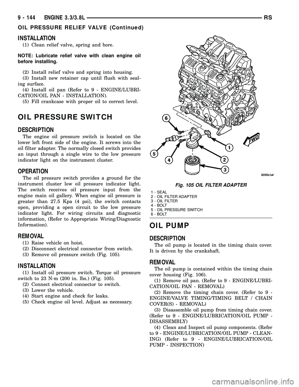
(3) Remove oil pressure switch (Fig. 105).
INSTALLATION
(1) Install oil pressure switch. Torque oil pressure
switch to 23 N´m (200 in. lbs.) (Fig. 105).
(2) Connect electrical connector to switch.
(3) Lower the vehicle.
(4) Start engine and check for leaks.
(5) Check engine oil level. Adjust as necessary.
OIL PUMP
DESCRIPTION
The oil pump is located in the timing chain cover.
It is driven by the crankshaft.
REMOVAL
The oil pump is contained within the timing chain
cover housing (Fig. 106).
(1) Remove oil pan. (Refer to 9 - ENGINE/LUBRI-
CATION/OIL PAN - REMOVAL)
(2) Remove the timing chain cover. (Refer to 9 -
ENGINE/VALVE TIMING/TIMING BELT / CHAIN
COVER(S) - REMOVAL)
(3) Disassemble oil pump from timing chain cover.
(Refer to 9 - ENGINE/LUBRICATION/OIL PUMP -
DISASSEMBLY)
(4) Clean and Inspect oil pump components. (Refer
to 9 - ENGINE/LUBRICATION/OIL PUMP - CLEAN-
ING) (Refer to 9 - ENGINE/LUBRICATION/OIL
PUMP - INSPECTION)
Fig. 105 OIL FILTER ADAPTER
1 - SEAL
2 - OIL FILTER ADAPTER
3 - OIL FILTER
4 - BOLT
5 - OIL PRESSURE SWITCH
6 - BOLT
9 - 144 ENGINE 3.3/3.8LRS
OIL PRESSURE RELIEF VALVE (Continued)
Page 1420 of 2339

ing connector and remove the upper shroud with the
traction control switch intact. Refer to the following
steps.
(13) If equipped with adjustable pedals, disconnect
the wiring connector for the switch (Fig. 7).
(14) Remove the lower shroud mounting screw
(Fig. 8), then remove the lower shroud.
(15) If equipped with traction control, disconnect
the wiring connector from the column wiring harness(Fig. 9). Remove the upper shroud with traction con-
trol switch.
(16) If equipped with Autostick, disconnect the
wiring connector (Fig. 9).
(17) Remove the cluster trim bezel. (Refer to 23 -
BODY/INSTRUMENT PANEL/CLUSTER BEZEL -
REMOVAL)
(18) Remove the screws fastening the fixed shroud
in place (Fig. 10). Remove the fixed shroud.
Fig. 7 Adjustable Pedals Switch Mounting
1 - LOWER SHROUD
2 - ADJUSTABLE PEDALS SWITCH
3 - WIRING CONNECTOR
Fig. 8 Lower Shroud Mounting
1 - STEERING COLUMN
2 - LOWER SHROUD
3 - MOUNTING SCREW
Fig. 9 Traction Control And Autostick Wiring
Connections
1 - TRACTION CONTROL WIRING CONNECTOR
2 - ROUTING CLIP
3 - AUTOSTICK WIRING CONNECTOR
4 - COLUMN WIRING HARNESS
Fig. 10 Fixed Shroud Mounting
1 - FIXED SHROUD
2 - MOUNTING SCREWS
RSCOLUMN19-13
COLUMN (Continued)
Page 1424 of 2339
(19) Position the lower shroud on the column (Fig.
8). Install the lower shroud mounting screw. Tighten
the screw to 2 N´m (17 in. lbs.) torque.
(20) If equipped with adjustable pedals, Connect
the wiring connector for the switch (Fig. 7) to the col-
umn wiring harness.
(21) Position the upper shroud on top of the lower
shroud and snap it into place. Install the upper
shroud mounting screws (Fig. 6). Tighten the screws
to 2 N´m (17 in. lbs.) torque.
(22) Inspect shroud mating surfaces for excessive
gaps and correct as necessary.
(23) Install the cluster trim bezel (Refer to 23 -
BODY/INSTRUMENT PANEL/CLUSTER BEZEL -
INSTALLATION).
(24) Install the knee blocker/steering column cover
plate. (Refer to 23 - BODY/INSTRUMENT PANEL/
KNEE BLOCKER - INSTALLATION)
(25) Install the parking brake handle link.
(26) Install the knee blocker/steering column open-
ing cover. (Refer to 23 - BODY/INSTRUMENT PAN-
EL/STEERING COLUMN OPENING COVER -
INSTALLATION)
(27) Align the splines and install the steering
wheel on the steering column shaft(Refer to 19 -
STEERING/COLUMN/STEERING WHEEL -
INSTALLATION).
(28) Install the damper over the steering column
shaft (Fig. 4).
(29) Install the steering wheel retaining bolt (Fig.
4). Tighten the bolt to 61 N´m (45 ft. lbs.) torque.
(30) If the steering wheel is equipped with remote
audio controls, connect the wiring connector to the
clockspring (Fig. 4).
(31) Connect the two squib connectors to the
driver airbag (Fig. 3). The connectors are color coded
to avoid connector mix-up.
(32) Connect the speed control and horn connector
to the clockspring (Fig. 3).
(33) Install the airbag to the steering wheel.
Install the driver airbag mounting screws (Fig. 2).
Tighten screws to 10 N´m (90 in. lbs.) torque.
(34) Connect the battery negative (ground) cable to
battery post following special Diagnosis And Testing
procedure. (Refer to 8 - ELECTRICAL/RESTRAINTS
- DIAGNOSIS AND TESTING)
(35) Check operation of all steering column
mounted components.
(36) Road test vehicle to ensure proper operation
of steering.SPECIFICATIONS
COLUMN FASTENER TORQUE
DESCRIPTION N´mFt.
Lbs.In.
Lbs.
Driver Airbag Mounting Screws 10 Ð 90
Multi-Function Switch Mounting
Housing Set-Screw14 Ð 124
Shroud Attaching Screws - Fixed 3 Ð 23
Shroud Attaching Screws -
Lower/Upper2Ð17
SKIM Attaching Screw 4 Ð 30
Steering Column Coupling Pinch
Bolt28 Ð 250
Steering Column Mounting Nuts 12 Ð 105
Steering Wheel Retaining Bolt 61 45 Ð
IGNITION SWITCH
REMOVAL
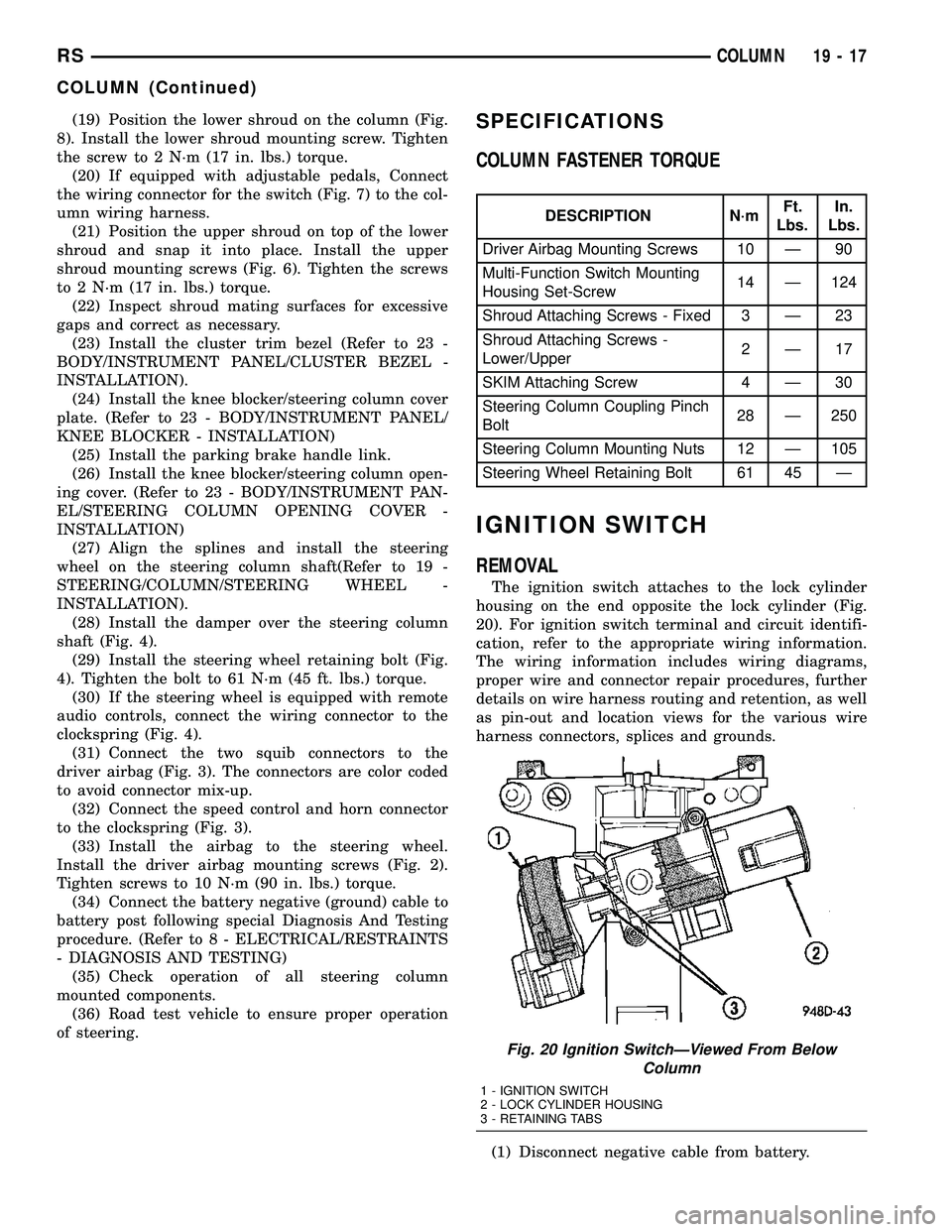
The ignition switch attaches to the lock cylinder
housing on the end opposite the lock cylinder (Fig.
20). For ignition switch terminal and circuit identifi-
cation, refer to the appropriate wiring information.
The wiring information includes wiring diagrams,
proper wire and connector repair procedures, further
details on wire harness routing and retention, as well
as pin-out and location views for the various wire
harness connectors, splices and grounds.
(1) Disconnect negative cable from battery.
Fig. 20 Ignition SwitchÐViewed From Below
Column
1 - IGNITION SWITCH
2 - LOCK CYLINDER HOUSING
3 - RETAINING TABS
RSCOLUMN19-17
COLUMN (Continued)
Page 1584 of 2339
VEHICLE SPEED SIGNAL
The vehicle speed signal is taken from the Output
Speed Sensor. The PCM converts this signal into a
pulse per mile signal and sends the vehicle speed
message across the communication bus to the BCM.
The BCM sends this signal to the Instrument Cluster
to display vehicle speed to the driver. The vehicle
speed signal pulse is roughly 8000 pulses per mile.
REMOVAL
(1) Disconnect battery negative cable.
(2) Raise vehicle on hoist.
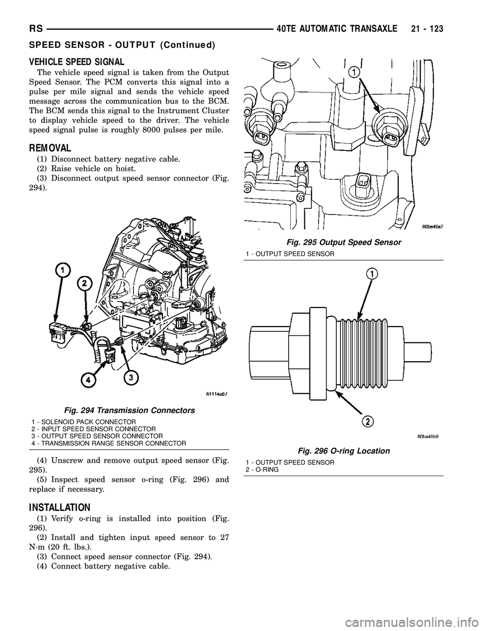
(3) Disconnect output speed sensor connector (Fig.
294).
(4) Unscrew and remove output speed sensor (Fig.
295).
(5) Inspect speed sensor o-ring (Fig. 296) and
replace if necessary.
INSTALLATION
(1) Verify o-ring is installed into position (Fig.
296).
(2) Install and tighten input speed sensor to 27
N´m (20 ft. lbs.).
(3) Connect speed sensor connector (Fig. 294).
(4) Connect battery negative cable.
Fig. 294 Transmission Connectors
1 - SOLENOID PACK CONNECTOR
2 - INPUT SPEED SENSOR CONNECTOR
3 - OUTPUT SPEED SENSOR CONNECTOR
4 - TRANSMISSION RANGE SENSOR CONNECTOR
Fig. 295 Output Speed Sensor
1 - OUTPUT SPEED SENSOR
Fig. 296 O-ring Location
1 - OUTPUT SPEED SENSOR
2 - O-RING
RS40TE AUTOMATIC TRANSAXLE21 - 123
SPEED SENSOR - OUTPUT (Continued)
Page 1734 of 2339
SPEED SENSOR - OUTPUT
DESCRIPTION
The Output Speed Sensor is a two-wire magnetic
pickup device that generates an AC signal as rotation
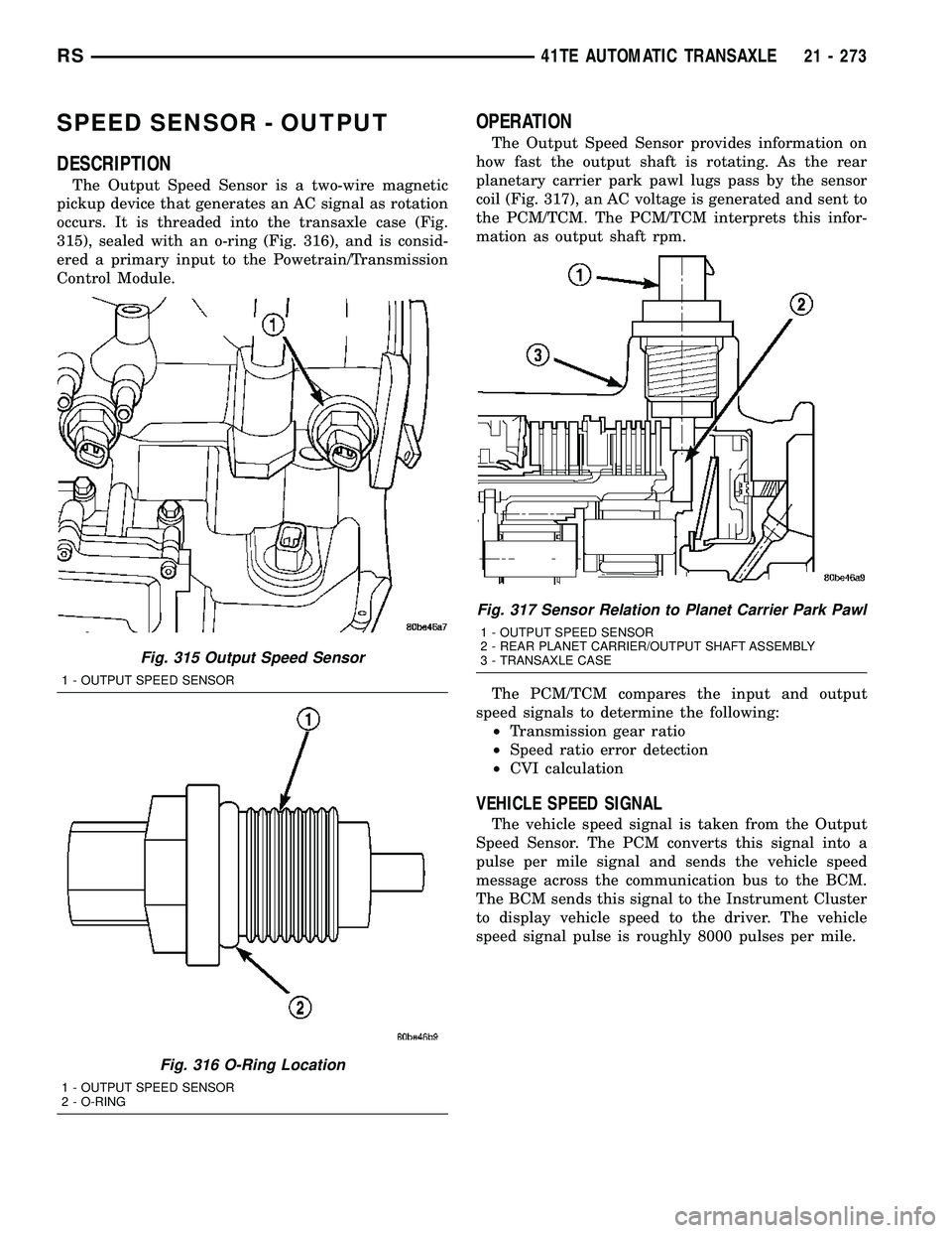
occurs. It is threaded into the transaxle case (Fig.
315), sealed with an o-ring (Fig. 316), and is consid-
ered a primary input to the Powetrain/Transmission
Control Module.
OPERATION
The Output Speed Sensor provides information on
how fast the output shaft is rotating. As the rear
planetary carrier park pawl lugs pass by the sensor
coil (Fig. 317), an AC voltage is generated and sent to
the PCM/TCM. The PCM/TCM interprets this infor-
mation as output shaft rpm.
The PCM/TCM compares the input and output
speed signals to determine the following:
²Transmission gear ratio
²Speed ratio error detection
²CVI calculation
VEHICLE SPEED SIGNAL
The vehicle speed signal is taken from the Output
Speed Sensor. The PCM converts this signal into a
pulse per mile signal and sends the vehicle speed
message across the communication bus to the BCM.
The BCM sends this signal to the Instrument Cluster
to display vehicle speed to the driver. The vehicle
speed signal pulse is roughly 8000 pulses per mile.
Fig. 315 Output Speed Sensor
1 - OUTPUT SPEED SENSOR
Fig. 316 O-Ring Location
1 - OUTPUT SPEED SENSOR
2 - O-RING
Fig. 317 Sensor Relation to Planet Carrier Park Pawl
1 - OUTPUT SPEED SENSOR
2 - REAR PLANET CARRIER/OUTPUT SHAFT ASSEMBLY
3 - TRANSAXLE CASE
RS41TE AUTOMATIC TRANSAXLE21 - 273
Page 1844 of 2339

INSTRUMENT PANEL
TABLE OF CONTENTS
page page
CLUSTER BEZEL
REMOVAL.............................65
INSTALLATION.........................65
CUP HOLDER
REMOVAL.............................65
INSTALLATION.........................65
GLOVE BOX
REMOVAL.............................66
INSTALLATION.........................66
GLOVE BOX LATCH
REMOVAL.............................66
INSTALLATION.........................66
GLOVE BOX LATCH STRIKER
REMOVAL.............................66
INSTALLATION.........................66
INSTRUMENT PANEL ASSEMBLY
REMOVAL.............................67
INSTALLATION.........................70
INSTRUMENT PANEL CENTER BEZEL
REMOVAL.............................71
INSTALLATION.........................72
INSTRUMENT PANEL RIGHT END CAP
REMOVAL.............................72INSTALLATION.........................72
INSTRUMENT PANEL TOP COVER
REMOVAL.............................72
INSTALLATION.........................72
LOWER CONSOLE
REMOVAL.............................73
INSTALLATION.........................73
LOWER INSTRUMENT PANEL
REMOVAL.............................73
INSTALLATION.........................73
LOWER STEERING COLUMN COVER
REMOVAL.............................74
INSTALLATION.........................74
BLOCKER- INFLATABLE KNEE
REMOVAL.............................75
INSTALLATION.........................75
OVER STEERING COLUMN COVER
REMOVAL.............................76
INSTALLATION.........................76
INSTRUMENT PANEL TOP PAD ASSEMBLY
REMOVAL.............................77
INSTALLATION.........................77
CLUSTER BEZEL
REMOVAL
(1) Disconnect and isolate the battery negative
cable.
(2) Remove Over Steering Column Bezel by lifting
it straight up with a firm pull.
(3) Remove the four bezel attaching screws (Fig.
1).
(4) Tilt the steering column in the full down posi-
tion.
(5) Pull rearward on the cluster bezel and remove.
INSTALLATION
(1) Maneuver cluster bezel over steering column
and into position (Fig. 1).
(2) Install the four bezel attaching screws.
(3) Install the Over Steering Column Bezel by
positioning it over the retaining slots and firmly
snapping it into place.
(4) Connect the battery negative cable.
CUP HOLDER
REMOVAL
(1) Remove the screw access cover from the bottom
of the center bezel.
(2) Remove the center bezel attaching screws.
(3) Using a trim stick (special tool # C-4755) or
equivalent, gently pry out on the edge of the instru-
ment panel center bezel. Hang off to the side leaving
the accessory switches connected.
(4) Pull the cup holder assembly rearward to dis-
engage the rear guide studs from instrument panel
(Fig. 2).
(5) Remove the cup holder assembly from lower
instrument panel.
INSTALLATION
(1) Ensure the cup holder assembly is in the closed
position. The cup holder assembly must be installed
as an assembly to ensure proper track position.
(2) Place the cup holder assembly into position in
the lower instrument panel and slide into opening
until the rear guide struts snap into place (Fig. 2).
(3) Install the center bezel.
RSINSTRUMENT PANEL23-65
Page 1845 of 2339

(4) Install the center bezel attaching screws
(5) Install the screw access cover to the bottom of
the center bezel.
GLOVE BOX
REMOVAL
(1) Open glove box.
(2) Push in on sides of glove box bin and lower
door.
(3) Pivot glove box downward and disengage hinge
hooks from instrument panel.
(4) Remove glove box.
INSTALLATION
(1) Place glove box in position.
(2) Engage hinge hooks into instrument panel and
pivot glove box upward.
(3) Push in sides of glove box bin and snap glove
box assembly into instrument panel.
(4) Close glove box door.
GLOVE BOX LATCH
REMOVAL
(1) Open glove box.
(2) Push in on sides of glove box bin and lower
door.
(3) Pivot glove box downward and disengage hinge
hooks from instrument panel.
(4) Remove glove box.
(5) Remove the assembly screws.
(6) Disassemble the glove box.
(7) Separate the latch from the glove box assembly.
INSTALLATION
(1) Install the latch onto the glove box assembly.
(2) Assemble the glove box.
(3) Install the assembly screws.
(4) Engage hinge hooks into instrument panel and
pivot glove box upward.
(5) Push in sides of glove box bin and snap glove
box assembly into instrument panel.
(6) Close glove box door.
GLOVE BOX LATCH STRIKER
REMOVAL
(1) Open glove box door.
(2) Remove screws holding lock striker to instru-
ment panel.
(3) Remove glove box latch striker.
INSTALLATION
(1) Install the glove box latch striker.
(2) Install the screws holding latch striker to
instrument panel.
(3) Close glove box door.
Fig. 1 INSTRUMENT PANEL CLUSTER BEZEL
1 - WIRE CONNECTOR
2 - SPEEDOMETER
3 - ATTACHING SCREW(S)
4 - INSTRUMENT PANEL CLUSTER BEZEL
5 - INSTRUMENT PANEL
6 - CENTER STACK FILLER BEZEL
7 - CUP HOLDER AND TRAY
Fig. 2 TRAY CUP HOLDER
1 - WIRE CONNECTOR
2 - CENTER SWITCH AND BEZEL ASSEMBLY
3 - ATTACHING SCREW(S)
4 - TRAY AND CUP HOLDER
23 - 66 INSTRUMENT PANELRS
CUP HOLDER (Continued)
Page 1847 of 2339

(13) Remove the right end cover by pulling out-
board.
(14) Remove the right side A-pillar retaining bolts
(Fig. 5). There are two 13 mm bolts and one 10 mm
bolt.
(15) Loosen the right side cowl side roll down bolt.
(16) Remove over steering column cover. (Refer to
23 - BODY/INSTRUMENT PANEL/STEERING COL-
UMN OPENING COVER - REMOVAL).
(17) Remove the cluster bezel. (Refer to 23 -
BODY/INSTRUMENT PANEL/CLUSTER BEZEL -
REMOVAL).
(18) Remove the lower steering column cover and
end cap. (Refer to 23 - BODY/INSTRUMENT PAN-
EL/LOWER STEERING COLUMN COVER -
REMOVAL)
(19) Remove the inflatable knee blocker. (Refer to
23 - BODY/INSTRUMENT PANEL/INFLATABLE
KNEE BLOCKER - REMOVAL)(20) Remove the two screws to the hood release
handle.
(21) Remove the two steering column fixed shroud
retaining screws (Fig. 6).
(22) Remove the four steering column shroud
retaining screws. Separate the steering column bear-
ing shroud and steering column shroud and remove
from vehicle (Fig. 6).
(23) Disconnect the left side wiring:
(a) Brake switch.
(b) Main bulkhead connector.
(c) Five harness connectors.
(d) Driver airbag connector.
(24) Disconnect the steering column wiring. There
are seven connectors and then unclip the harness
from the column.
(25) Disconnect the Occupant Restraint Controller
(ORC) harness connector.
Fig. 4 INSTRUMENT PANEL REMOVAL
1 - INSTRUMENT PANEL
2 - SIX ATTACHING SCREWS
3 - 13 mm BOLT - TWO ON EACH SIDE4 - ROLL DOWN BRACKET
5 - 10 mm BOLT - STARTING BOLT ONE EACH SIDE
23 - 68 INSTRUMENT PANELRS
INSTRUMENT PANEL ASSEMBLY (Continued)
Page 1850 of 2339
(7) Place steering column cover plate into position
(Fig. 8).
(8) Install six instrument panel steering column
cover plate attaching screws.
(9) Install the screws attaching the instrument
panel reinforcement (Fig. 9).
(10) Place brake pedal support bracket into posi-
tion and install three nuts attaching to instrument
panel.
(11) Place steering column into position and install
four nuts retaining the steering column to the dash
panel steering column mounting bracket and lower
column to the floor (Fig. 7).
(12) Connect the Occupant Restraint Controller
(ORC) harness connector.
(13) Connect the steering column wiring. There
are seven connectors and clip the harness to the col-
umn.
(14) Connect the left side wiring:
(a) Brake switch.
(b) Main bulkhead connector.
(c) Five harness connectors.
(d) Driver airbag connector.
(15) Place steering column bearing shroud and
steering column shroud into position and install four
steering column shroud retaining screws (Fig. 6).
(16) Place fixed shroud into position and install
two steering column fixed shroud retaining screws
(Fig. 6).
(17) Install two screws to the hood release handle.
(18) Install the inflatable knee blocker. (Refer to
23 - BODY/INSTRUMENT PANEL/KNEE BLOCKER
- INSTALLATION).
(19) Install the lower steering column cover and
end cap. (Refer to 23 - BODY/INSTRUMENT PAN-
EL/LOWER STEERING COLUMN COVER AND
END CAP - INSTALLATION).
(20) Install the cluster bezel. (Refer to 23 - BODY/
INSTRUMENT PANEL/CLUSTER BEZEL -
INSTALLATION).
(21) Install over steering column cover. (Refer to
23 - BODY/INSTRUMENT PANEL/STEERING COL-
UMN OPENING COVER - INSTALLATION).
(22) Install the right end cover. Position over
retaining slots and firmly snap into place.
(23) Connect the right side wire connectors to the
HVAC behind the glove box area and the two
antenna connectors behind the glove box hinge.
(24) Install the glove box:
(a) Install glove box into the vehicle. Line up the
hinges and firmly snap together.(b) Push in on sides of glove box bin and raise
door.
(25) Install two screws to each right and left cowl
trim covers.
(26) Connect the wire connectors to the Passenger
Airbag.
(27) Install the screws attaching the instrument
panel frame to the dash panel below windshield
opening.
(28) Install screws attaching instrument panel
frame to the dash panel below windshield opening
(Fig. 4).
(29) Install the instrument panel top cover and
silencer. (Refer to 23 - BODY/INSTRUMENT PAN-
EL/INSTRUMENT PANEL TOP PAD - INSTALLA-
TION).
(30) Install both left and right side A-pillar trim
covers.
(31) Install bolts attaching the lower supports to
the floor pan (Fig. 3).
(32) Install bolts attaching the lower supports to
the instrument panel frame.
(33) Install the lower console:
(a) Install lower console to vehicle.
(b) Connect the auxiliary power outlet.
(c) Install the six retaining screws.
(34) Connect the battery negative cable.
INSTRUMENT PANEL CENTER
BEZEL
REMOVAL
(1) Disconnect and isolate the battery negative
cable.
(2) Insert the trim stick (special tool #C-4755) or
equivalent between access cover and center bezel
gently pry outward.
(3) Carefully pry the access cover from the instru-
ment panel (Fig. 10).
(4) Remove the two center bezel attaching screws.
(5) Using a trim stick or equivalent, gently pry out
on the edge of the instrument panel center bezel and
pull outward.
(6) Disconnect the wire connectors to the accessory
switches and HVAC control.
(7) Remove the instrument panel center bezel from
the vehicle.
RSINSTRUMENT PANEL23-71
INSTRUMENT PANEL ASSEMBLY (Continued)
Page 1856 of 2339
INSTRUMENT PANEL TOP PAD
ASSEMBLY
REMOVAL
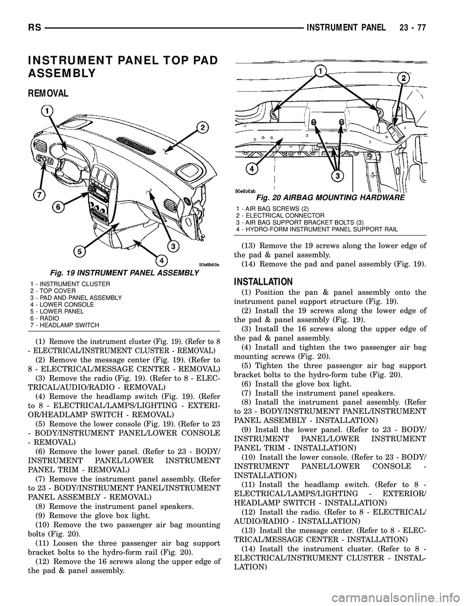
(1)Remove the instrument cluster (Fig. 19). (Refer to 8
- ELECTRICAL/INSTRUMENT CLUSTER - REMOVAL)
(2) Remove the message center (Fig. 19). (Refer to
8 - ELECTRICAL/MESSAGE CENTER - REMOVAL)
(3) Remove the radio (Fig. 19). (Refer to 8 - ELEC-
TRICAL/AUDIO/RADIO - REMOVAL)
(4) Remove the headlamp switch (Fig. 19). (Refer
to 8 - ELECTRICAL/LAMPS/LIGHTING - EXTERI-
OR/HEADLAMP SWITCH - REMOVAL)
(5) Remove the lower console (Fig. 19). (Refer to 23
- BODY/INSTRUMENT PANEL/LOWER CONSOLE
- REMOVAL)
(6) Remove the lower panel. (Refer to 23 - BODY/
INSTRUMENT PANEL/LOWER INSTRUMENT
PANEL TRIM - REMOVAL)
(7) Remove the instrument panel assembly. (Refer
to 23 - BODY/INSTRUMENT PANEL/INSTRUMENT
PANEL ASSEMBLY - REMOVAL)
(8) Remove the instrument panel speakers.
(9) Remove the glove box light.
(10) Remove the two passenger air bag mounting
bolts (Fig. 20).
(11) Loosen the three passenger air bag support
bracket bolts to the hydro-form rail (Fig. 20).
(12) Remove the 16 screws along the upper edge of
the pad & panel assembly.(13) Remove the 19 screws along the lower edge of
the pad & panel assembly.
(14) Remove the pad and panel assembly (Fig. 19).
INSTALLATION
(1) Position the pan & panel assembly onto the
instrument panel support structure (Fig. 19).
(2) Install the 19 screws along the lower edge of
the pad & panel assembly (Fig. 19).
(3) Install the 16 screws along the upper edge of
the pad & panel assembly.
(4) Install and tighten the two passenger air bag
mounting screws (Fig. 20).
(5) Tighten the three passenger air bag support
bracket bolts to the hydro-form tube (Fig. 20).
(6) Install the glove box light.
(7) Install the instrument panel speakers.
(8) Install the instrument panel assembly. (Refer
to 23 - BODY/INSTRUMENT PANEL/INSTRUMENT
PANEL ASSEMBLY - INSTALLATION)
(9) Install the lower panel. (Refer to 23 - BODY/
INSTRUMENT PANEL/LOWER INSTRUMENT
PANEL TRIM - INSTALLATION)
(10) Install the lower console. (Refer to 23 - BODY/
INSTRUMENT PANEL/LOWER CONSOLE -
INSTALLATION)
(11) Install the headlamp switch. (Refer to 8 -
ELECTRICAL/LAMPS/LIGHTING - EXTERIOR/
HEADLAMP SWITCH - INSTALLATION)
(12) Install the radio. (Refer to 8 - ELECTRICAL/
AUDIO/RADIO - INSTALLATION)
(13)
Install the message center. (Refer to 8 - ELEC-
TRICAL/MESSAGE CENTER - INSTALLATION)
(14) Install the instrument cluster. (Refer to 8 -
ELECTRICAL/INSTRUMENT CLUSTER - INSTAL-
LATION)
Fig. 19 INSTRUMENT PANEL ASSEMBLY
1 - INSTRUMENT CLUSTER
2 - TOP COVER
3 - PAD AND PANEL ASSEMBLY
4 - LOWER CONSOLE
5 - LOWER PANEL
6 - RADIO
7 - HEADLAMP SWITCH
Fig. 20 AIRBAG MOUNTING HARDWARE
1 - AIR BAG SCREWS (2)
2 - ELECTRICAL CONNECTOR
3 - AIR BAG SUPPORT BRACKET BOLTS (3)
4 - HYDRO-FORM INSTRUMENT PANEL SUPPORT RAIL
RSINSTRUMENT PANEL23-77