CLUSTER CHRYSLER CARAVAN 2005 Owner's Manual
[x] Cancel search | Manufacturer: CHRYSLER, Model Year: 2005, Model line: CARAVAN, Model: CHRYSLER CARAVAN 2005Pages: 2339, PDF Size: 59.69 MB
Page 405 of 2339
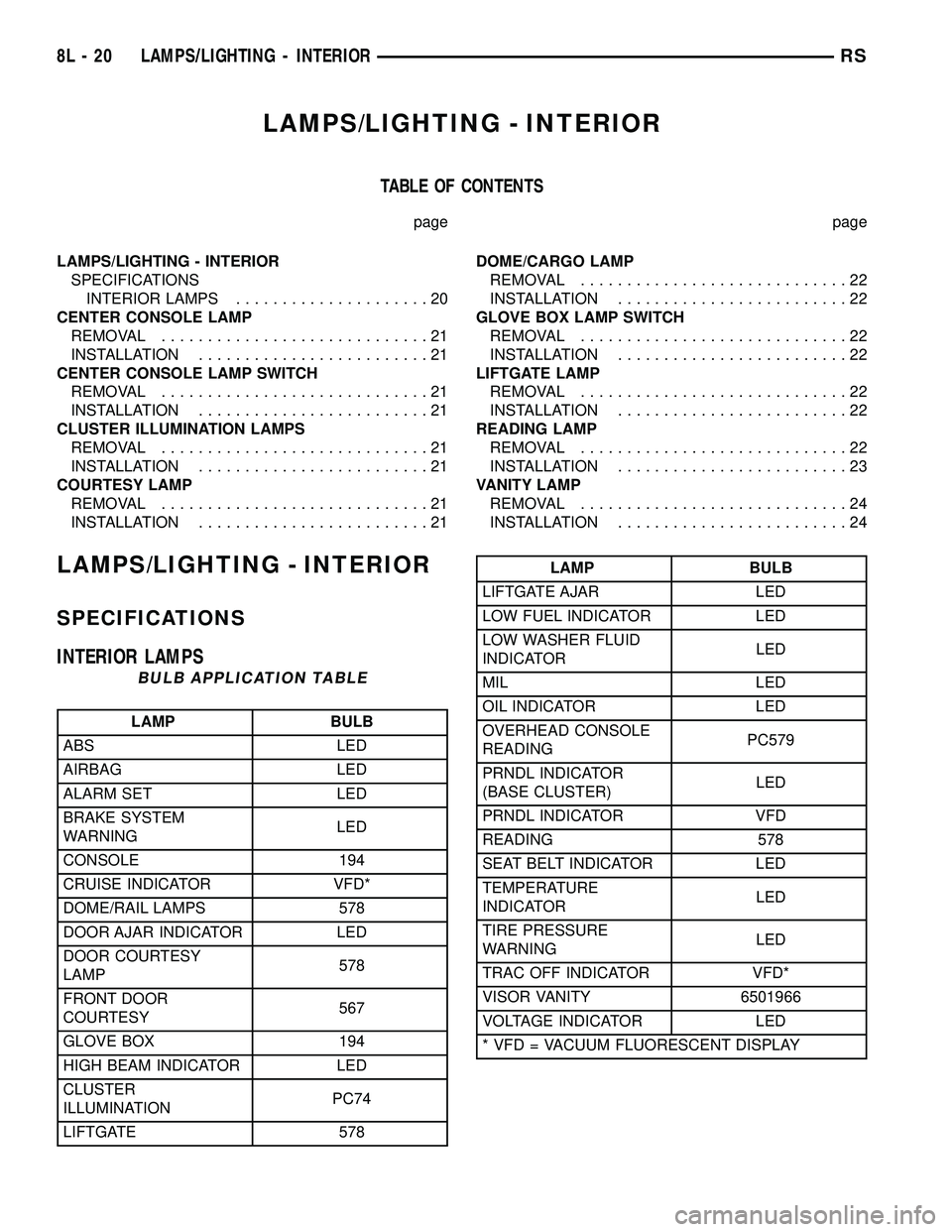
LAMPS/LIGHTING - INTERIOR
TABLE OF CONTENTS
page page
LAMPS/LIGHTING - INTERIOR
SPECIFICATIONS
INTERIOR LAMPS.....................20
CENTER CONSOLE LAMP
REMOVAL.............................21
INSTALLATION.........................21
CENTER CONSOLE LAMP SWITCH
REMOVAL.............................21
INSTALLATION.........................21
CLUSTER ILLUMINATION LAMPS
REMOVAL.............................21
INSTALLATION.........................21
COURTESY LAMP
REMOVAL.............................21
INSTALLATION.........................21DOME/CARGO LAMP
REMOVAL.............................22
INSTALLATION.........................22
GLOVE BOX LAMP SWITCH
REMOVAL.............................22
INSTALLATION.........................22
LIFTGATE LAMP
REMOVAL.............................22
INSTALLATION.........................22
READING LAMP
REMOVAL.............................22
INSTALLATION.........................23
VANITY LAMP
REMOVAL.............................24
INSTALLATION.........................24
LAMPS/LIGHTING - INTERIOR
SPECIFICATIONS
INTERIOR LAMPS
BULB APPLICATION TABLE
LAMP BULB
ABS LED
AIRBAG LED
ALARM SET LED
BRAKE SYSTEM
WARNINGLED
CONSOLE 194
CRUISE INDICATOR VFD*
DOME/RAIL LAMPS 578
DOOR AJAR INDICATOR LED
DOOR COURTESY
LAMP578
FRONT DOOR
COURTESY567
GLOVE BOX 194
HIGH BEAM INDICATOR LED
CLUSTER
ILLUMINATIONPC74
LIFTGATE 578
LAMP BULB
LIFTGATE AJAR LED
LOW FUEL INDICATOR LED
LOW WASHER FLUID
INDICATORLED
MIL LED
OIL INDICATOR LED
OVERHEAD CONSOLE
READINGPC579
PRNDL INDICATOR
(BASE CLUSTER)LED
PRNDL INDICATOR VFD
READING 578
SEAT BELT INDICATOR LED
TEMPERATURE
INDICATORLED
TIRE PRESSURE
WARNINGLED
TRAC OFF INDICATOR VFD*
VISOR VANITY 6501966
VOLTAGE INDICATOR LED
* VFD = VACUUM FLUORESCENT DISPLAY
8L - 20 LAMPS/LIGHTING - INTERIORRS
Page 406 of 2339
CENTER CONSOLE LAMP
REMOVAL
(1) Disconnect and isolate the battery negative
cable.
(2) Open up console lid.
(3) Remove console tray.
(4) Using a trim stick (special tool #C-4755) or
equivalent, gently pry down on lamp. Make sure not
to let lamp fall into console base.
NOTE: If preferred, a 5/16 piece of hose approxi-
mately 4±6 inches long may be used to pull lamp
from socket. Push hose over end of lamp and pull
down.
INSTALLATION
NOTE: If preferred, a 5/16 piece of hose approxi-
mately 4±6 inches long may be used to install the
new lamp. Push lamp into hose just far enough to
hold bulb. Locate the socket slot and push firmly
up. Make sure not to let lamp fall into console base.
When bulb is seated, twist hose 1/4 turn to remove
from lamp.
(1) Place lamp in socket slot and push firmly up.
Make sure not to let lamp fall into console base.
(2) Install the console tray.
(3) Close console lid.
(4) Connect the battery negative cable.
CENTER CONSOLE LAMP
SWITCH
REMOVAL
(1) Disconnect and isolate the battery negative
cable.
(2) Open console lid and remove tray.
(3) Using a flat bladed tool, pry up on the switch.
(4) Remove bulb from switch.
INSTALLATION
(1) Install bulb into switch.
(2) Push switch into console opening.
(3) Install tray and close lid.
(4) Connect battery negative cable.
CLUSTER ILLUMINATION
LAMPS
REMOVAL
(1) Remove the Instrument Cluster. Refer to Elec-
trical, Instrument Cluster, Removal.
(2) Turn over cluster and expose the illumination
bulb sockets.
(3) Identify which bulb is defective and twist it out
of the cluster using a counterclockwise motion.
INSTALLATION
(1) Install the new bulb socket into the cluster
using a clockwise motion.
(2) Install the Instrument Cluster. Refer to Electri-
cal, Instrument Cluster, Installation.
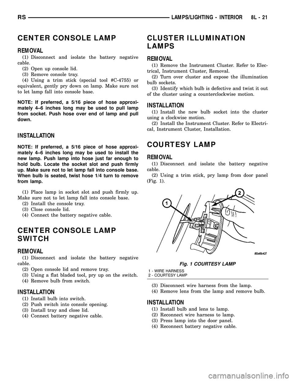
COURTESY LAMP
REMOVAL
(1) Disconnect and isolate the battery negative
cable.
(2) Using a trim stick, pry lamp from door panel
(Fig. 1).
(3) Disconnect wire harness from the lamp.
(4) Remove lens from the lamp and remove bulb.
INSTALLATION
(1) Install bulb and lens to lamp.
(2) Reconnect wire harness to lamp.
(3) Press lamp into the door panel.
(4) Reconnect battery negative cable.
Fig. 1 COURTESY LAMP
1 - WIRE HARNESS
2 - COURTESY LAMP
RSLAMPS/LIGHTING - INTERIOR8L-21
Page 417 of 2339
function currently displayed is a function that can be
reset. The distance to service function can also be
reset using the local reset method, but it will reset
back to the Service Interval distance that is set in
the EVIC programmable features mode. (Refer to 8 -
ELECTRICAL/OVERHEAD CONSOLE/ELEC-
TRONIC VEHICLE INFO CENTER - STANDARD
PROCEDURE).
DIAGNOSIS AND TESTING
ELECTRONIC VEHICLE INFORMATION CENTER
Electronic Vehicle Information Center (EVIC) data
is obtained from the Body Control Module (BCM) on
the Programmable Communications Interface (PCI)
Data Bus circuit. The EVIC will display dashes (- -)
for any of the screens it did not receive the bus mes-
sages. The label corresponding to the missing infor-
mation will be lit. If no EVIC data is displayed,
check the PCI Data Bus circuit communications and
the BCM. If the dimming level is improper check the
PCI Data Bus circuit.
The use of a DRBIIItscan tool and the proper
diagnostic procedures information are recommended
for further testing of the EVIC module and the PCI
data bus circuit. Perform the SELF-DIAGNOSTIC
TEST before replacing the EVIC module (Refer to 8 -
ELECTRICAL/OVERHEAD CONSOLE - DIAGNO-
SIS AND TESTING).
STANDARD PROCEDURE
ELECTRONIC VEHICLE INFORMATION CENTER
PROGRAMMING
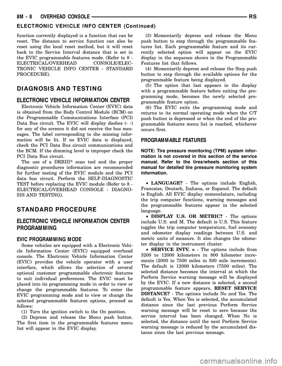
EVIC PROGRAMMING MODE
Some vehicles are equipped with a Electronic Vehi-
cle Information Center (EVIC) equipped overhead
console. The Electronic Vehicle Information Center
(EVIC) provides the vehicle operator with a user
interface, which allows the selection of several
optional customer programmable electronic features
to suit individual preferences. The EVIC must be
placed into its programming mode in order to view or
change the programmable features. To enter the
EVIC programming mode and to view or change the
selected programmable features options, proceed as
follows:
(1) Turn the ignition switch to the On position.
(2) Depress and release the Menu push button.
The first item in the programmable features menu
list will appear in the EVIC display.(3) Momentarily depress and release the Menu
push button to step through the programmable fea-
tures list. Each programmable feature and its cur-
rently selected option will appear on the EVIC
display in the sequence shown in the Programmable
Features list that follows.
(4) Momentarily depress and release the Step push
button to step through the available options for the
programmable feature being displayed.
(5) The option that last appears in the display
with a programmable feature before exiting the pro-
gramming mode, becomes the newly selected pro-
grammable feature option.
(6) The EVIC exits the programming mode and
returns to its normal operating mode when the C/T
push button is depressed or when the end of the pro-
grammable features menu list is reached, whichever
occurs first.
PROGRAMMABLE FEATURES
NOTE: Tire pressure monitoring (TPM) system infor-
mation is not covered in this section of the service
manual. Refer to the tires/wheels section of this
manual for detailed tire pressure monitoring system
information.
²LANGUAGE?- The options include English,
Francaise, Deutsch, Italiana, or Espanol. The default
is English. All EVIC display nomenclature, including
the trip computer functions, warning messages and
the programmable features appear in the selected
language.
²DISPLAY U.S. OR METRIC?- The options
include U.S. and M. The default is U.S. This feature
toggles the trip computer temperature, fuel economy
and odometer display readings between U.S. and
metric units of measure. It also changes the odome-
ter display in the instrument cluster.
²SERVICE INTV. =- The options include from
3200 to 12000 kilometers in 800 kilometer incre-
ments (2000 to 7500 miles in 500 mile increments).
The default is 12000 kilometers (7500 miles). The
selected distance becomes the interval at which the
Perform Service warning message will be displayed
by the EVIC. If a new distance is selected, a second
programmable feature appears,RESET SERVICE
DISTANCE?- The options include No and Yes. The
default is Yes. When Yes is selected, the accumulated
distance since the last previous Perform Service
warning message will be reset to zero because the
service interval has been changed. When No is
selected, the distance until the next Perform Service
warning message is reduced by the accumulated dis-
tance since the last previous message.
8M - 8 OVERHEAD CONSOLERS
ELECTRONIC VEHICLE INFO CENTER (Continued)
Page 489 of 2339

SEAT BELT & RETRACTOR - SECOND ROW -
RIGHT OUTBOARD
REMOVAL.............................40
INSTALLATION.........................40
SEAT BELT & RETRACTOR - SECOND ROW -
RIGHT OUTBOARD WITH REAR HVAC - LWB
REMOVAL.............................41
INSTALLATION.........................41
SEAT BELT & RETRACTOR - SECOND ROW -
LEFT OUTBOARD
REMOVAL.............................42INSTALLATION.........................42
SEAT BELT TENSIONER
DESCRIPTION.........................43
OPERATION...........................43
SEAT WEIGHT BLADDER & PRESSURE
SENSOR
DESCRIPTION.........................43
OPERATION...........................44
RESTRAINTS
DESCRIPTION
This vehicle is equipped with a Frontal Impact Air-
bag System, which utilizes the driver/passenger air-
bags, two front impact sensors, and seat belt
tensioners located in the front seat belt buckles. This
system is designed to protect occupants in the event
of a front impact collision. These airbags are all ser-
viceable parts. The tensioners are integral to the
front seat belt buckles. If these pyrotechnics are
deployed or defective, they must be replaced.
Vehicles equipped with the Side Impact Airbag
System utilize a curtain airbag, three side impact
sensors, and the Occupant Restraint Controller
(ORC) to determine if the airbag should be deployed.
Following a side impact event where the side airbag
was deployed, the headliner as well as the curtain
airbag must be replaced.
The occupant restraints include both active and
passive types. Active restraints are those which
require the vehicle occupants to take some action to
employ, such as fastening a seat belt; while passive
restraints require no action by the vehicle occupants
to be employed.
ACTIVE RESTRAINTS
The active restraints include:
²Front Seat Belts- Both front seating positions
are equipped with three-point seat belt systems
employing a lower B-pillar mounted inertia latch-
type retractor, height-adjustable upper B-pillar
mounted turning loops, a fixed lower seat belt anchor
secured to the lower B-pillar, and a traveling end-re-
lease buckle secured to the inboard side of the seat
cushion frame. The driver side front seat belt buckle
includes an integral Hall-effect seat belt switch that
detects whether the driver side front seat belt has
been fastened.²Rear Seat Belts- Both outboard rear second
and third seating positions are equipped with three-
point seat belt systems. The outboard seating posi-
tion belts employ a lower C or D-pillar mounted
inertia latch-type retractor, a fixed position upper C
or D-pillar mounted turning loop, and a fixed lower
seat belt anchor secured to the inboard side of the
seat cushion frame.
²Child Restraint Anchors- Also equipped in
this vehicle are two, fixed-position, child seat upper
tether anchors located on the lower seat cushion, in
the rear of the lower seat cushion. There is one
anchor integral to the back of the third row seat back
panel, one on each seat back panel. Two lower second
row anchors are also provided for each rear outboard
seating position. The lower anchors are integral to
the seat cushion frame and are accessed from the
front of the second row seat where the seat back
meets the seat cushion.
PASSIVE RESTRAINTS
The passive restraints available for this model
include the following:
²Dual Front Airbags- Multistage driver. front
passenger, and driver knee blocker airbags are avail-
able for this model. This airbag system is a passive,
inflatable, Supplemental Restraint System (SRS) and
vehicles with this equipment can be readily identified
by the ªSRS - AIRBAGº logo molded into the driver
airbag trim cover in the center of the steering wheel
and also into the passenger airbag door on the
instrument panel above the glove box. Vehicles with
the airbag system can also be identified by the airbag
indicator, which will illuminate in the instrument
cluster for about seven seconds as a bulb test each
time the ignition switch is turned to the ON position.
A pyrotechnic-type seat belt tensioner is integral to
the driver and passenger front seat belt buckle of all
models equipped with dual front airbags.
8O - 2 RESTRAINTSRS
Page 490 of 2339
²Occupant Classification System- These
vehicles also include an Occupant Classification Sys-
tem (OCS) with components that are located on or in
the passenger front seat cushion. These components
include an Occupant Classification Module (OCM)
and a seat weight bladder and pressure sensor
assembly. In addition, this system includes a belt
tension sensor integral to the lower anchor of the
passenger side front seat belt. Vehicles equipped with
the OCS can be readily identified by a Passenger Air-
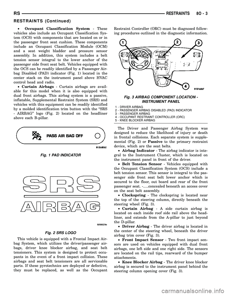
bag Disabled (PAD) indicator (Fig. 1) located in the
center stack on the instrument panel above HVAC
control head and radio.
²Curtain Airbags- Curtain airbags are avail-
able for this model when it is also equipped with
dual front airbags. This airbag system is a passive,
inflatable, Supplemental Restraint System (SRS) and
vehicles with this equipment can be readily identified
by a molded identification trim button with the ªSRS
- AIRBAGº logo (Fig. 2) located on the headliner
above each B-pillar.
This vehicle is equipped with a Frontal Impact Air-
bag System, which utilizes the driver/passenger air-
bags, driver knee blocker airbag, and seat belt
tensioners. This system is designed to protect occu-
pants in the event of a front impact collision. These
airbags and seat belt tensioners are all serviceable
parts. If these pyrotechnics are deployed or defective,
they must be replaced, as well as the OccupantRestraint Controller (ORC) must be diagnosed follow-
ing procedures outlined in the diagnostic information.
The Driver and Passenger Airbag System was
designed to reduce the likelihood of injury or death
in frontal collisions. Each separate system is supple-
mental (Fig. 2) orPassiveto the primary restraint
device, which are the seat belts.
²Airbag Indicator- The airbag indicator is inte-
gral to the Instrument Cluster, which is located on
the instrument panel in front of the driver.
²Belt Tension Sensor- Vehicles equipped with
the Occupant Classification System (OCS) include a
belt tension sensor. This sensor is integral to the pas-
senger side front seat belt lower anchor which is
secured to the floor, out board and rear of the front
passenger seat. -.....concealed beneath an access cover
on the seat belt assembly.
²Clockspring- The clockspring is located near
the top of the steering column, directly beneath the
steering wheel (Fig. 3).
²Curtain Airbag- A side curtain airbag is
located on each inside roof side rail above the head-
liner, and extends from the A-pillar to just beyond
the D-pillar.
²Driver Airbag- The driver airbag is located in
the center of the steering wheel, beneath the driver
airbag trim cover (Fig. 3).
²Front Impact Sensor- Two front impact sen-
sors are used on vehicles equipped with dual front
airbags, one left side and one right side. The sensors
are located on the rail tips, rearward of the bumper
attachments.
²Knee Blocker Airbag- The driver knee blocker
airbag is secured to the instrument panel behind the
steering column opening cover (Fig. 3).
Fig. 1 PAD INDICATOR
Fig. 2 SRS LOGO
Fig. 3 AIRBAG COMPONENT LOCATION -
INSTRUMENT PANEL
1 - DRIVER AIRBAG
2 - PASSENGER AIRBAG DISABLED (PAD) INDICATOR
3 - PASSENGER AIRBAG
4 - OCCUPANT RESTRAINT CONTROLLER (ORC)
5 - KNEE BLOCKER AIRBAG
RSRESTRAINTS8O-3
RESTRAINTS (Continued)
Page 491 of 2339
²Occupant Classification Module- Vehicles
equipped with the Occupant Classification System
(OCS) include an Occupant Classification Module
(OCM) which is secured to a stamped steel mounting
bracket on the underside of the passenger side front
seat cushion frame.
²Occupant Restraint Controller- The Occu-
pant Restraint Controller (ORC) is also sometimes
referred to as the Airbag Control Module (ACM). The
ORC is located on a mount on the floor transmission
tunnel just underneath the instrument panel center
stack (Fig. 3).
²Passenger Airbag- The passenger airbag is
located on the instrument panel, beneath the instru-
ment panel top pad and above the glove box on the
passenger side of the vehicle (Fig. 3).
²Passenger Airbag Disabled (PAD) Indicator
- Vehicles equipped with the Occupant Classification
System (OCS) include a passenger airbag disabled
(PAD) indicator which is located in the instrument
panel center stack (Fig. 3).
²Passenger Knee Blocker- The passenger knee
blocker is a structural reinforcement that is integral
to and concealed within the glove box door (Fig. 3).
²Seat Belt Tensioner- A seat belt tensioner is
integral to both front seat belt buckles. The seat belt
buckles are secured to the inner seat frame sides,
beneath a cushion trim panel.
²Seat Weight Bladder and Pressure Sensor
Assembly- Vehicles equipped with the Occupant
Classification System (OCS) include a seat weight
bladder that is sandwiched between an insulator pad
on the top of the passenger side front seat pan and
the seat cushion foam padding. A short hose connects
the bladder to a pressure sensor which is secured to
the Occupant Classification Module (OCM) mounting
bracket on the underside of the passenger side front
seat cushion frame.
²Side Impact Sensors- Six side impact sensors
are used on vehicles equipped with the curtain air-
bags, three left side and three right side. The first
row side impact sensor is located in the B-pillar, just
above the front seat belt retractor. The second row
side impact sensor is located in the sliding side door
track opening, just in front of the C-pillar. The third
row side impact sensor is located behind the quarter
trim panel, above the rear tire wheel well, between
the C and D-pillars.
The ORC, the OCM, and the cluster each contain a
microprocessor and programming that allow them to
communicate with each other using the Programma-
ble Communications Interface (PCI) data bus net-
work. This method of communication is used by the
ORC for control of the airbag indicators.OPERATION
ACTIVE RESTRAINTS
The primary passenger restraints in this or any
other vehicle are the seat belts and child restraint
anchors. Seat belts and child restraint anchors are
referred to as an active restraint because the vehicle
occupants are required to physically fasten and prop-
erly adjust these restraints in order to benefit from
them. See the owner's manual in the vehicle glove
box for more information on the features, use and
operation of all of the active restraints.
PASSIVE RESTRAINTS
The passive restraints are referred to as a supple-
mental restraint system because they were designed
and are intended to enhance the protection for the
occupants of the vehicleONLYwhen used in con-
junction with the seat belts. They are referred to as
passive restraints because the vehicle occupants are
not required to do anything to make them operate;
however, the vehicle occupants must be wearing their
seat belts in order to obtain the maximum safety
benefit from the supplemental restraint system.
The supplemental restraint system electrical cir-
cuits are continuously monitored and controlled by a
microprocessor and software contained within the
Occupant Restraint Controller (ORC). An airbag indi-
cator in the ElectroMechanical Instrument Cluster
(EMIC) illuminates for about seven seconds as a bulb
test each time the ignition switch is turned to the
ON or START positions. Following the bulb test, the
airbag indicator is turned ON or OFF by the ORC to
indicate the status of the supplemental restraint sys-
tem. If the airbag indicator comes ON at any time
other than during the bulb test, it indicates that
there is a problem in the supplemental restraint sys-
tem electrical circuits. Such a problem may cause air-
bags not to deploy when required, or to deploy when
not required.
Deployment of the supplemental restraints
depends upon the angle and severity of an impact.
Deployment is not based upon vehicle speed; rather,
deployment is based upon the rate of deceleration as
measured by the forces of gravity (G force) upon the
impact sensors. When an impact is severe enough,
the microprocessor in the ORC signals the inflator of
the appropriate airbag units to deploy their airbag
cushions. The front seat belt tensioners are provided
with a deployment signal by the ORC in conjunction
with the front airbags. During a frontal vehicle
impact, the knee blockers work in concert with prop-
erly fastened and adjusted seat belts to restrain both
the driver and the front seat passenger in the proper
position for an airbag deployment. The knee blockers
also absorb and distribute the crash energy from the
8O - 4 RESTRAINTSRS
RESTRAINTS (Continued)
Page 493 of 2339

experienced, exit the vehicle for fresh air until
the irritation ceases. If irritation continues, see
a physician.
Do not use a replacement airbag that is not in
the original packaging. This may result in
improper deployment, personal injury, or
death.
The factory installed fasteners, screws and
bolts used to fasten airbag components have a
special coating and are specifically designed
for the airbag system. Do not use substitute fas-
teners. Use only original equipment fasteners
listed in the parts catalog when fastener
replacement is required.
During, and following, any child restraint
anchor service, due to impact event or vehicle
repair, carefully inspect all mounting hard-
ware, tether straps, and anchors for proper
installation, operation, or damage. If a child
restraint anchor is found damaged in any way,
the anchor must be replaced. Failure to do this
may result in personal injury or death.
Deployed and nondeployed airbags may or
may not have live pyrotechnic material within
the airbag inflator. Do not dispose of driver/
passenger/seat/curtain/knee blocker airbags or
seat belt tensioners unless you are sure of com-
plete deployment. Refer to the Hazardous Sub-
stance Control System for proper disposal.
Dispose of deployed airbags and tensioners
consistent with state, provincial, local, and fed-
eral regulations.
After any airbag component testing or ser-
vice, do not connect the battery negative cable
(Refer to 8 - ELECTRICAL/RESTRAINTS -
DIAGNOSIS AND TESTING - AIRBAG SYSTEM).
Personal injury or death may result if the sys-
tem test is not performed first.
If the vehicle is equipped with the Occupant
Classification System (OCS), do not connect the
battery negative cable before performing the
OCS Verification Test using the scan tool and
the appropriate diagnostic information. Per-
sonal injury or death may result if the system
test is not performed properly.
Never replace both the Occupant Restraint
Controller (ORC) and the Occupant Classifica-
tion Module (OCM) at the same time. If both
require replacement, replace one, then perform
the Airbag System test (Refer to 8 - ELECTRI-
CAL/RESTRAINTS - DIAGNOSIS AND TESTING
- AIRBAG SYSTEM) before replacing the other.
Both the ORC and the OCM store Occupant
Classification System (OCS) calibration data,
which they transfer to one another when one of
them is replaced. If both are replaced at thesame time, an irreversible fault will be set in
both modules and the OCS may malfunction
and cause personal injury or death.
DIAGNOSIS AND TESTING - AIRBAG SYSTEM
(1) With the battery negative remote cable discon-
nected, connect the scan tool to the Data Link Con-
nector (DLC).
(2) Turn the ignition key to the ON position, then
exit vehicle with the scan tool.
(3) After checking that no one is inside the vehicle,
connect the battery negative remote terminal.
(4) Read and record theACTIVEDiagnostic Trou-
ble Code (DTC) data.
(5) Read and record anySTOREDDTC's.
(6) Refer to the proper diagnostic information if
any DTC's are found in Step 4 and Step 5.
(7) If the airbag warning lamp either fails to light,
or goes ON and stays ON, there is a system malfunc-
tion. To test the airbag warning lamp (bulb) opera-
tion in the cluster (Refer to 8 - ELECTRICAL/
INSTRUMENT CLUSTER - DIAGNOSIS AND
TESTING). Refer to the proper diagnostic informa-
tion for any other system problems.
STANDARD PROCEDURE
STANDARD PROCEDURE - HANDLING
AIRBAGS
DEPLOYED AIRBAG
WARNING: The vehicle interior may contain a very
small amount of powder, a by-product of airbag
deployment. This powder can irritate the skin, eyes,
nose and throat. Wear safety glasses, rubber
gloves, and long sleeved clothing when cleaning
any of the powder residue from the vehicle. If you
find that the cleanup is irritating your skin, run cool
water over the affected area. Also, if you experience
nasal or throat irritation, exit the vehicle for fresh
air until the irritation ceases. If irritation continues,
see a physician.
8O - 6 RESTRAINTSRS
RESTRAINTS (Continued)
Page 515 of 2339
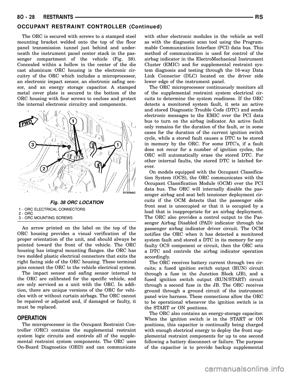
The ORC is secured with screws to a stamped steel
mounting bracket welded onto the top of the floor
panel transmission tunnel just behind and under-
neath the instrument panel center stack in the pas-
senger compartment of the vehicle (Fig. 38).
Concealed within a hollow in the center of the die
cast aluminum ORC housing is the electronic cir-
cuitry of the ORC which includes a microprocessor,
an electronic impact sensor, an electronic safing sen-
sor, and an energy storage capacitor. A stamped
metal cover plate is secured to the bottom of the
ORC housing with four screws to enclose and protect
the internal electronic circuitry and components.
An arrow printed on the label on the top of the
ORC housing provides a visual verification of the
proper orientation of the unit, and should always be
pointed toward the front of the vehicle. The ORC
housing has integral mounting flanges. the ORC has
two molded plastic electrical connectors that exits the
right facing side of the ORC housing. These terminal
pins connect the ORC to the vehicle electrical system.
The impact sensor and safing sensor internal to
the ORC are calibrated for the specific vehicle, and
are only serviced as a unit with the ORC. In addi-
tion, there are unique versions of the ORC for vehi-
cles with or without curtain airbags. The ORC cannot
be repaired or adjusted and, if damaged or faulty, it
must be replaced.
OPERATION
The microprocessor in the Occupant Restraint Con-
troller (ORC) contains the supplemental restraint
system logic circuits and controls all of the supple-
mental restraint system components. The ORC uses
On-Board Diagnostics (OBD) and can communicatewith other electronic modules in the vehicle as well
as with the diagnostic scan tool using the Program-
mable Communication Interface (PCI) data bus. This
method of communication is used for control of the
airbag indicator in the ElectroMechanical Instrument
Cluster (EMIC) and for supplemental restraint sys-
tem diagnosis and testing through the 16-way Data
Link Connector (DLC) located on the driver side
lower edge of the instrument panel.
The ORC microprocessor continuously monitors all
of the supplemental restraint system electrical cir-
cuits to determine the system readiness. If the ORC
detects a monitored system fault, it sets an active
and stored Diagnostic Trouble Code (DTC) and sends
electronic messages to the EMIC over the PCI data
bus to turn on the airbag indicator. An active fault
only remains for the duration of the fault, or in some
cases for the duration of the current ignition switch
cycle, while a stored fault causes a DTC to be stored
in memory by the ORC. For some DTC's, if a fault
does not recur for a number of ignition cycles, the
ORC will automatically erase the stored DTC. For
other internal faults, the stored DTC is latched for-
ever.
On models equipped with the Occupant Classifica-
tion System (OCS), the ORC communicates with the
Occupant Classification Module (OCM) over the PCI
data bus. The ORC will internally disable the pas-
senger airbag and seat belt tensioner deployment cir-
cuits if the OCM detects that the passenger side
front seat is unoccupied or that it is occupied by a
load that is inappropriate for an airbag deployment.
The ORC also provides a control output to the Pas-
senger Airbag Disabled (PAD) indicator through the
passenger airbag indicator driver circuit. The OCM
notifies the ORC when it has detected a monitored
system fault and stored a DTC in its memory for any
faulty OCS component or circuit, then the ORC sets
a DTC and controls the airbag indicator operation
accordingly.
The ORC receives battery current through two cir-
cuits; a fused ignition switch output (RUN) circuit
through a fuse in the Junction Block (JB), and a
fused ignition switch output (RUN/START) circuit
through a second fuse in the JB. The ORC receives
ground through a ground circuit of the instrument
panel wire harness. These connections allow the ORC
to be operational whenever the ignition switch is in
the START or ON positions.
The ORC also contains an energy-storage capacitor.
When the ignition switch is in the START or ON
positions, this capacitor is continually being charged
with enough electrical energy to deploy the front sup-
plemental restraint components for up to one second
following a battery disconnect or failure. The purpose
of the capacitor is to provide backup supplemental
Fig. 38 ORC LOCATION
1 - ORC ELECTRICAL CONNECTORS
2 - ORC
3 - ORC MOUNTING SCREWS
8O - 28 RESTRAINTSRS
OCCUPANT RESTRAINT CONTROLLER (Continued)
Page 530 of 2339
SEAT BELT TENSIONER
DESCRIPTION
The seat belt system incorporates Seat Belt Ten-
sioners. The tensioner is designed to hold the occu-
pant in their respective seat by retracting the seat
belt up to four inches. They are integral to the front
seat belt buckles and cannot be serviced. If found
defective they must be replaced. After an airbag
deployment, the tensioner must be replaced.
Seat Belt Tensioners supplement the dual front air-
bag system. The seat belt tensioners are integral to
the front seat belt buckles, which are secured to the
seat cushion frame on the inboard side. The seat belt
tensioners are controlled by the Occupant Restraint
Controller (ORC) and are connected to the vehicle
electrical system through the body wire harness.
The seat belt tensioners cannot be repaired and, if
faulty or damaged, the entire front seat belt buckle
must be replaced. The seat belt tensioners are not
intended for reuse and must be replaced following
any front airbag deployment.
OPERATION
WARNING: When the front airbag is deployed, the
tensioner will have deployed also and should be
replaced. Failure to do so could result in occupant
personal injury or death.
The seat belt tensioners are deployed by a signal
generated by the Occupant Restraint Controller
(ORC) through the driver or passenger seat belt ten-
sioner line 1 and line 2 (or squib) circuits. When the
ORC sends the proper electrical signal to the tension-
ers, the electrical energy generates enough heat to
initiate a small pyrotechnic gas generator.
Removing excess slack from the front seat belts not
only keeps the occupants properly positioned for an
airbag deployment following a frontal impact of the
vehicle, but also helps to reduce injuries that the
occupants of the front seat might experience in these
situations as a result of a harmful contact with the
steering wheel, steering column, instrument panel
and/or windshield.
The ORC monitors the condition of the seat belt
tensioners through circuit resistance, and will illumi-
nate the airbag indicator in the ElectroMechanical
Instrument Cluster (EMIC) and store a Diagnostic
Trouble Code (DTC) for any fault that is detected.
For proper diagnosis of the seat belt tensioners, use a
scan tool and the appropriate diagnostic information.
SEAT WEIGHT BLADDER &
PRESSURE SENSOR
DESCRIPTION
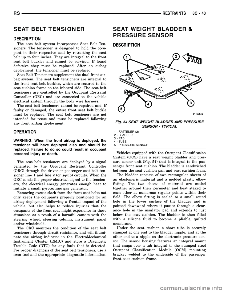
Vehicles equipped with the Occupant Classification
System (OCS) have a seat weight bladder and pres-
sure sensor unit (Fig. 54) that is integral to the pas-
senger front seat cushion. The bladder is sandwiched
between the seat cushion pan and seat cushion foam.
The bladder consists of two rectangular sheets of
an elastomeric material and a molded plastic elbow
fitting. The two sheets of material are sealed
together around their perimeter and heat staked to
each other at numerous regular points within their
field. The elbow fitting is sealed to a small round
hole in the lower surface of the bladder and is
pointed downward where it passes through a clear-
ance hole in the insulator pad and extends to just
below the seat cushion. The bladder is then filled
with a silicone fluid to become a pliable, quilted
membrane.
Under the seat cushion a short tube is securely
clamped at one end to the bladder nipple, and at the
other end to a nipple on the electronic pressure sen-
sor. The sensor housing features an integral mount
that snaps over a tab integral to the stamped steel
Occupant Classification Module (OCM) mounting
bracket welded to the underside of the passenger
front seat cushion frame.
Fig. 54 SEAT WEIGHT BLADDER AND PRESSURE
SENSOR - TYPICAL
1 - FASTENER (2)
2 - BLADDER
3-PAD
4 - TUBE
5 - PRESSURE SENSOR
RSRESTRAINTS8O-43
Page 534 of 2339
OPERATION
The PCM on NGC vehicles first senses that the
speed control is set. If the set speed is exceeded by
more than 4 mph (6.5 km/hr) and the throttle is
closed, the PCM on NGC vehicles causes the trans-
axle to downshift to THIRD gear. After downshifting,
the automatic speed control resumes normal opera-
tion. To ensure that an upshift is appropriate after
the set speed is reached, the PCM on NGC vehicles
waits until the speed control system opens the throt-
tle at least 6 degrees before upshifting to OVER-
DRIVE again.
If the driver applies the brakes, canceling auto-
matic speed control operation with the transaxle still
in THIRD gear, the PCM on NGC vehicles maintains
this gear until the driver opens the throttle at least 6
degrees to avoid an inappropriate upshift. The
upshift is also delayed for 2.5 seconds after reaching
the 6 degrees throttle opening in anticipation that
the driver might open the throttle enough to require
THIRD gear. This will avoid unnecessary and dis-
turbing transmission cycling. If the automatic speed
control RESUME feature is used after braking, the
upshift is delayed until the set speed is achieved to
reduce cycling and provide better response.
DIAGNOSIS AND TESTING - ROAD TEST
Perform a vehicle road test to verify reports of
speed control system malfunction. The road test
should include attention to the speedometer. Speed-
ometer operation should be smooth and without flut-
ter at all speeds.Flutter in the speedometer indicates a problem
which might cause surging in the speed control sys-
tem. The cause of any speedometer problems should
be corrected before proceeding. Refer to the Instru-
ment Cluster for speedometer diagnosis.
If a road test verifies an inoperative system, and
the speedometer operates properly, check for:
²A Diagnostic Trouble Code (DTC). If a DTC
exists, conduct tests per the Powertrain Diagnostic
Procedures manual.
²A misadjusted brake (stop) lamp switch. This
could also cause an intermittent problem.
²Loose or corroded electrical connections at the
servo. Corrosion should be removed from electrical
terminals and a light coating of Mopar Multipurpose
Grease, or equivalent, applied.
²Leaking vacuum reservoir.
²Loose or leaking vacuum hoses or connections.
²Defective one-way vacuum check valve.
²Secure attachment at both ends of the speed
control servo cable.
²Smooth operation of throttle linkage and throttle
body air valve.
²Conduct electrical test at PCM.
²Failed speed control servo. Do the servo vacuum
test.
CAUTION: When test probing for voltage or conti-
nuity at electrical connectors, care must be taken
not to damage connector, terminals or seals. If
these components are damaged, intermittent or
complete system failure may occur.
SPECIFICATIONS - TORQUE
DESCRIPTION N´m Ft. Lbs. In. Lbs.
Servo Mounting Bracket
Nuts14 10.3 123.9
Servo Mounting Bracket
Bolts14 10.3 123.9
Servo Mounting Nuts 6.7 60
RSSPEED CONTROL8P-3
SPEED CONTROL (Continued)