ABS CHRYSLER CARAVAN 2005 Service Manual
[x] Cancel search | Manufacturer: CHRYSLER, Model Year: 2005, Model line: CARAVAN, Model: CHRYSLER CARAVAN 2005Pages: 2339, PDF Size: 59.69 MB
Page 37 of 2339
Kilometers 110 000
km120 000
km130 000
km140 000
km150 000
km160 000
km
Replace fuel filter/water
separator unit.XX X
Flush and replace engine
coolant.X
Check front end alignment. X X X
Inspect the tie rod ends and
boot seals.XX
Inspect the brake linings. XXXXX X
Inspection and service should also be performed
anytime a malfunction is observed or suspected.
Retain all receipts.
³ Replace if there is superficial wear, bearing clear-
ance, or evident grease leakage.
WARNING: You can be badly injured working on or
around a motor vehicle. Do only that service work
for which you have the knowledge and the right
equipment. If you have any doubt about your ability
to perform a service job, take your vehicle to a
competent mechanic.
HOISTING
STANDARD PROCEDURE - HOISTING
Refer to Owner's Manual provided with vehicle for
proper emergency jacking procedures.
WARNING: THE HOISTING AND JACK LIFTING
POINTS PROVIDED ARE FOR A COMPLETE VEHI-
CLE. WHEN THE ENGINE OR REAR SUSPENSION
IS REMOVED FROM A VEHICLE, THE CENTER OF
GRAVITY IS ALTERED MAKING SOME HOISTING
CONDITIONS UNSTABLE. PROPERLY SUPPORT OR
SECURE VEHICLE TO HOISTING DEVICE WHEN
THESE CONDITIONS EXIST.CAUTION: Do not position hoisting device on any
suspension component, including the front suspen-
sion crossmember, the rear leaf springs, and the
rear axle. Do not hoist on the front and rear
bumpers, the lower liftgate crossmember, the lower
radiator crossmember, the down standing flanges
on the sill or the front engine mount.
FOR PROPER HOIST PLACEMENT REFER
TO (Fig. 5).
The hoisting points are identified by S.A.E.
inverted triangle hoisting symbols (Fig. 5). The front
hoisting points are at the bottom of the font rail
below the hoisting symbol approximately 250 mm
behind the front suspension crossmember. When
using outboard lift hoists, verify that the hoist lift
pads have been properly adjusted to eliminate con-
tact between the hoist arm and the down standing
flange on the sill. The rear hoisting points are the
leaf spring front mounting brackets. The hoist pad
must be positioned to pick up the flanges on the
bracket, not the leaf spring.
When servicing the leaf springs or the leaf spring
mounting brackets, special provisions are required to
support the rear of the vehicle. Position the rear
hoist pads under the horizontal surface on the bot-
tom of the sill, inboard adjacent to the flange and
centered fore/aft between the jacking indicator tabs
on the lower flange.DO NOT HOIST ON THE
FLANGE.Place a soft pad between the hoist and the
painted surface on the sill to avoid scratching the fin-
ish.
0 - 24 LUBRICATION & MAINTENANCERS
MAINTENANCE SCHEDULES (Continued)
Page 39 of 2339
CAUTION: Do not crank starter motor on disabled
vehicle for more than 15 seconds, starter may over-
heat and could fail.
(7) If engine does not start within 15 seconds, stop
cranking engine and allow starter to cool (15 min-
utes), before cranking again.
DISCONNECT CABLE CLAMPS AS FOLLOWS:
²Disconnect BLACK cable clamp from engine
ground on disabled vehicle.
²When using a Booster vehicle, disconnect
BLACK cable clamp from battery negative terminal.
Disconnect RED cable clamp from battery positive
terminal.
²Disconnect RED cable clamp from battery posi-
tive terminal on disabled vehicle.
TOWING
STANDARD PROCEDURE - TOWING
WARNINGS AND CAUTIONS
WARNING: DO NOT ALLOW TOWING ATTACHMENT
DEVICES TO CONTACT THE FUEL TANK OR LINES,
FUEL LEAK CAN RESULT.
DO NOT LIFT OR TOW VEHICLE BY FRONT OR
REAR BUMPER.
DO NOT GO UNDER A LIFTED VEHICLE IF NOT
SUPPORTED PROPERLY ON SAFETY STANDS.
DO NOT ALLOW PASSENGERS TO RIDE IN A
TOWED VEHICLE.USE A SAFETY CHAIN THAT IS INDEPENDENT
FROM THE TOWING ATTACHMENT DEVICE.
CAUTION: Do not damage brake lines, exhaust sys-
tem, shock absorbers, sway bars, or any other
under vehicle components when attaching towing
device to vehicle.
Do not secure vehicle to towing device by the use
of front or rear suspension or steering components.
Remove or secure loose or protruding objects from
a damaged vehicle before towing.
Refer to state and local rules and regulations before
towing a vehicle.
Do not allow weight of towed vehicle to bear on
lower fascia, air dams, or spoilers.
RECOMMENDED TOWING EQUIPMENT
To avoid damage to bumper fascia and air dams
use:
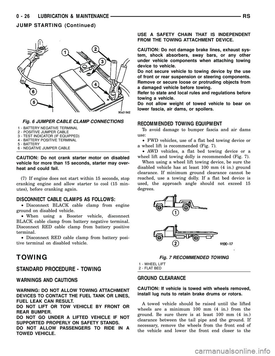
²FWD vehicles, use of a flat bed towing device or
a wheel lift is recommended (Fig. 7).
²AWD vehicles, a flat bed towing device or a
wheel lift and towing dolly is recommended (Fig. 7).
When using a wheel lift towing device, be sure the
disabled vehicle has at least 100 mm (4 in.) ground
clearance. If minimum ground clearance cannot be
reached, use a towing dolly. If a flat bed device is
used, the approach angle should not exceed 15
degrees.
GROUND CLEARANCE
CAUTION: If vehicle is towed with wheels removed,
install lug nuts to retain brake drums or rotors.
A towed vehicle should be raised until the lifted
wheels are a minimum 100 mm (4 in.) from the
ground. Be sure there is at least 100 mm (4 in.)
clearance between the tail pipe and the ground. If
necessary, remove the wheels from the front end of
the vehicle and lower the front end closer to the
Fig. 6 JUMPER CABLE CLAMP CONNECTIONS
1 - BATTERY NEGATIVE TERMINAL
2 - POSITIVE JUMPER CABLE
3 - TEST INDICATOR (IF EQUIPPED)
4 - BATTERY POSITIVE TERMINAL
5 - BATTERY
6 - NEGATIVE JUMPER CABLE
Fig. 7 RECOMMENDED TOWING
1 - WHEEL LIFT
2 - FLAT BED
0 - 26 LUBRICATION & MAINTENANCERS
JUMP STARTING (Continued)
Page 43 of 2339
FRONT SUSPENSION
DESCRIPTION - FRONT SUSPENSION
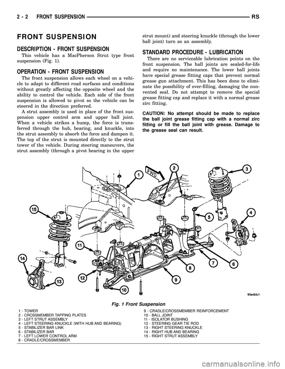
This vehicle has a MacPherson Strut type front
suspension (Fig. 1).
OPERATION - FRONT SUSPENSION
The front suspension allows each wheel on a vehi-
cle to adapt to different road surfaces and conditions
without greatly affecting the opposite wheel and the
ability to control the vehicle. Each side of the front
suspension is allowed to pivot so the vehicle can be
steered in the direction preferred.
A strut assembly is used in place of the front sus-
pension upper control arm and upper ball joint.
When a vehicle strikes a bump, the force is trans-
ferred through the hub, bearing, and knuckle, into
the strut assembly to absorb the force and dampen it.
The top of the strut is mounted directly to the strut
tower of the vehicle. During steering maneuvers, the
strut assembly (through a pivot bearing in the upperstrut mount) and steering knuckle (through the lower
ball joint) turn as an assembly.
STANDARD PROCEDURE - LUBRICATION
There are no serviceable lubrication points on the
front suspension. The ball joints are sealed-for-life
and require no maintenance. The lower ball joints
have special grease fitting caps that prevent normal
grease gun attachment. This has been done to elimi-
nate the possibility of over-filling, damaging the non-
vented seal. Do not attempt to remove the special
grease fitting cap and replace it with a normal grease
zirc fitting.
CAUTION: No attempt should be made to replace
the ball joint grease fitting cap with a normal zirc
fitting or fill the ball joint with grease. Damage to
the grease seal can result.
Fig. 1 Front Suspension
1 - TOWER
2 - CROSSMEMBER TAPPING PLATES
3 - LEFT STRUT ASSEMBLY
4 - LEFT STEERING KNUCKLE (WITH HUB AND BEARING)
5 - STABILIZER BAR LINK
6 - STABILIZER BAR
7 - LEFT LOWER CONTROL ARM
8 - CRADLE/CROSSMEMBER9 - CRADLE/CROSSMEMBER REINFORCEMENT
10 - BALL JOINT
11 - ISOLATOR BUSHING
12 - STEERING GEAR TIE ROD
13 - RIGHT STEERING KNUCKLE
14 - RIGHT HUB AND BEARING
15 - RIGHT STRUT ASSEMBLY
2 - 2 FRONT SUSPENSIONRS
Page 46 of 2339
HUB / BEARING
DESCRIPTION
The front wheel bearing and front wheel hub of
this vehicle are a hub and bearing unit type assem-
bly (Unit III). This unit combines the front wheel
mounting hub (flange) and the front wheel bearing
into a sealed one-piece unit. The hub and bearing is
mounted to the center of the steering knuckle (Fig.
1). It is retained by four mounting bolts accessible
from the inboard side of the steering knuckle. The
hub flange has five wheel mounting studs.
The wheel mounting studs used to mount the tire
and wheel to the vehicle are the only replaceable
components of the hub and bearing assembly. Other-
wise, the hub and bearing is serviced only as a com-
plete assembly.
OPERATION
The hub and bearing has internal bearings that
allow the hub to rotate with the driveshaft, along
with the tire and wheel. The five wheel mounting
studs mount the tire and wheel, and brake rotor to
the vehicle.
DIAGNOSIS AND TESTING - HUB AND
BEARING
The condition of the front hub and bearing assem-
bly is diagnosed using the inspection and testing pro-
cedure detailed below.
The bearing contained in the Unit III front hub/
bearing assembly will produce noise and vibration
when worn or damaged. The noise will generally
change when the bearings are loaded. A road test of
the vehicle is normally required to determine the
location of a worn or damaged bearing.
Find a smooth level road surface and bring the
vehicle up to a constant speed. When vehicle is at a
constant speed, swerve the vehicle back and forth
from the left and to the right. This will load and
unload the bearings and change the noise level.
When bearing damage is slight, the noise is some-
times noticeable at lower speeds and at other times
is more noticeable at speeds above 105 km/h (65
mph).
REMOVAL
NOTE: Replacement of the Unit III front hub/bearing
assembly can be normally done without having to
remove the steering knuckle from the vehicle. In the
event that the hub/bearing is frozen in the steering
knuckle and cannot be removed by hand, it will
have to be pressed out of the steering knuckle. The
steering knuckle will require removal from the vehi-
cle to allow the hub/bearing assembly to bepressed out of the steering knuckle. (Refer to 2 -
SUSPENSION/FRONT/KNUCKLE - REMOVAL)
(1) Raise vehicle. (Refer to LUBRICATION &
MAINTENANCE/HOISTING - STANDARD PROCE-
DURE)
(2) Remove wheel lug nuts, and front tire and
wheel assembly.
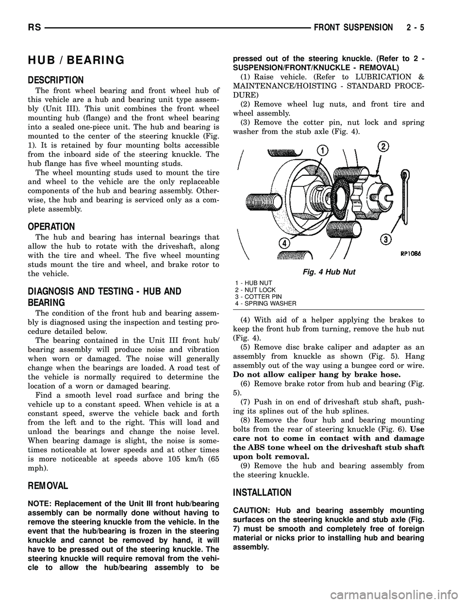
(3) Remove the cotter pin, nut lock and spring
washer from the stub axle (Fig. 4).
(4) With aid of a helper applying the brakes to
keep the front hub from turning, remove the hub nut
(Fig. 4).
(5) Remove disc brake caliper and adapter as an
assembly from knuckle as shown (Fig. 5). Hang
assembly out of the way using a bungee cord or wire.
Do not allow caliper hang by brake hose.
(6) Remove brake rotor from hub and bearing (Fig.
5).
(7) Push in on end of driveshaft stub shaft, push-
ing its splines out of the hub splines.
(8) Remove the four hub and bearing mounting
bolts from the rear of steering knuckle (Fig. 6).Use
care not to come in contact with and damage
the ABS tone wheel on the driveshaft stub shaft
upon bolt removal.
(9) Remove the hub and bearing assembly from
the steering knuckle.
INSTALLATION
CAUTION: Hub and bearing assembly mounting
surfaces on the steering knuckle and stub axle (Fig.
7) must be smooth and completely free of foreign
material or nicks prior to installing hub and bearing
assembly.
Fig. 4 Hub Nut
1 - HUB NUT
2 - NUT LOCK
3 - COTTER PIN
4 - SPRING WASHER
RSFRONT SUSPENSION2-5
Page 67 of 2339

REAR SUSPENSION
TABLE OF CONTENTS
page page
REAR SUSPENSION
DESCRIPTION - REAR SUSPENSION.......26
SPECIFICATIONS
REAR SUSPENSION FASTENER TORQUE . . 28
SPECIAL TOOLS
REAR SUSPENSION...................28
BUSHING - LEAF SPRING FRONT
REMOVAL.............................29
INSTALLATION.........................30
HUB / BEARING
DESCRIPTION.........................30
OPERATION...........................30
DIAGNOSIS AND TESTING - HUB AND
BEARING............................31
REMOVAL.............................31
INSTALLATION.........................33
JOUNCE BUMPER
DESCRIPTION.........................35
OPERATION...........................35
REMOVAL
REMOVAL - AWD, HEAVY DUTY, CARGO . . . 36
REMOVAL - FRONT-WHEEL-DRIVE.......36
INSTALLATION
INSTALLATION - AWD, HEAVY DUTY,
CARGO.............................36
INSTALLATION - FRONT-WHEEL-DRIVE....36
SHOCK ABSORBER
DESCRIPTION.........................36
OPERATION...........................36
REMOVAL - SHOCK ABSORBER...........36
DISASSEMBLY - SHOCK ABSORBER (UPPER
BUSHING)...........................37
ASSEMBLY - SHOCK ABSORBER (UPPER
BUSHING)...........................37
INSTALLATION - SHOCK ABSORBER........38
SPRING - AWD
REMOVAL.............................38INSTALLATION.........................39
SPRING - CARGO
REMOVAL.............................40
INSTALLATION.........................40
SPRING - FWD
REMOVAL.............................40
INSTALLATION.........................42
SPRING MOUNTS - FRONT
REMOVAL.............................42
INSTALLATION.........................43
SPRING MOUNTS - REAR
REMOVAL.............................43
INSTALLATION.........................43
SPRING SHACKLE
REMOVAL.............................44
INSTALLATION.........................44
STABILIZER BAR
DESCRIPTION.........................44
OPERATION...........................44
REMOVAL
REMOVAL - AWD......................44
REMOVAL - FWD.....................45
REMOVAL - FWD - FOLD-IN-FLOOR
SEATING............................45
INSTALLATION
INSTALLATION - AWD..................45
INSTALLATION - FWD..................45
INSTALLATION - FWD - FOLD-IN-FLOOR
SEATING............................45
TRACK BAR
DESCRIPTION.........................45
OPERATION...........................46
REMOVAL.............................46
INSTALLATION.........................46
REAR SUSPENSION
DESCRIPTION - REAR SUSPENSION
The rear suspension design on this vehicle uses
leaf springs, and a tube and casting axle (Fig. 1) (Fig.
2). The leaf springs used on the rear suspension of
this vehicle are of either a mono-leaf or multi-leaf
design.
There are four different rear suspension designs
available:²Front-Wheel-Drive
²Front-Wheel-Drive with Fold-in-Floor Seating
²All-Wheel-Drive
²Front-Wheel-Drive Commercial
The Front-Wheel-Drive (FWD) rear suspension
uses an axle that is mounted to mono-leaf springs
using isolator bushings at the axle mounting brack-
ets. The stabilizer bar mounts behind the axle.
2 - 26 REAR SUSPENSIONRS
Page 68 of 2339

The Front-Wheel-Drive with Fold-in-Floor Seating
rear suspension is very much like the FWD rear sus-pension except for the fact that the stabilizer bar
mounts in from of the axle.
The All-Wheel-Drive (AWD) rear suspension uses a
unique axle that is mounted to multi-leaf springs,
and does not use isolator bushings between the rear
axle and the leaf springs.
The Front-Wheel-Drive Cargo rear suspension uses
multi-leaf springs and a different rear axle than
either the standard FWD or AWD. It also does not
utilize a stabilizer bar. It is very similarly to the
AWD suspension.
The rear suspension consists of these major compo-
nents:
²Leaf springs (One each side)
²Jounce bumpers (One each side)
²Shock absorbers (One each side)
²Hub and bearings (One each side)
²Track bar
²Stabilizer bar
Fig. 1 Front-Wheel-Drive Rear Suspension
1 - SHACKLE 7 - LEAF SPRING (MONO-LEAF)
2 - REAR MOUNT (HANGER) 8 - ISOLATOR
3 - TRACK BAR 9 - FWD REAR AXLE
4 - SPRING PLATE 10 - STABILIZER BAR LINKS
5 - ISOLATOR 11 - STABILIZER BAR
6 - FRONT MOUNT (HANGER)
Fig. 2 All-Wheel-Drive Rear Suspension
1 - SHACKLE
2 - REAR MOUNT (HANGER)
3 - LEAF SPRING (MULTI-LEAF)
4 - AWD REAR AXLE
RSREAR SUSPENSION2-27
REAR SUSPENSION (Continued)
Page 69 of 2339

SPECIFICATIONS
REAR SUSPENSION FASTENER TORQUE
DESCRIPTION N´mFt.
Lbs.In.
Lbs.
Hub And Bearing Mounting
Bolts129 95 Ð
Hub And Bearing Axle Hub
Nut244 180 Ð
Jounce Bumper Mounting
Bolt33 24 290
Leaf Spring Front Mount-To-
Body Bolts61 45 Ð
Leaf Spring Front Pivot Bolt 156 115 Ð
Leaf Spring Plate-To-Axle
Bolts95 70 Ð
Leaf Spring Rear Mount-To-
Body Bolts61 45 Ð
Leaf Spring Shackle Plate
Nuts61 45 Ð
Shock Absorber Mounting
Bolts88 65 Ð
Stabilizer Bar Bushing
Retainer Bolts61 45 Ð
Stabilizer Bar Link Nuts 61 45 Ð
Stabilizer Bar Link Frame
Bracket Mounting Bolts61 45 Ð
Track Bar Bracket-To-Body
Mount Bolts61 45 Ð
Track Bar Pivot Bolts 95 70 Ð
Wheel Mounting (Lug) Nut 135 100 Ð
SPECIAL TOOLS
REAR SUSPENSION
Remover, Hub/Bearing 8458
Remover/Installer, Bushing 8459
Remover/Installer, Bushing 8526
Press, Ball Joint C-4212F
2 - 28 REAR SUSPENSIONRS
REAR SUSPENSION (Continued)
Page 70 of 2339

BUSHING - LEAF SPRING
FRONT
REMOVAL
(1) Raise vehicle on frame-contact hoist as follows:
(a) Position the hoist arm supporting the corner
of the vehicle to be serviced against a block of wood
placed on the body sill as shown (Fig. 3).
(b) Position the remaining hoist arms at each
corner of the vehicle in the normal fashion. (Refer
to LUBRICATION & MAINTENANCE/HOISTING
- STANDARD PROCEDURE)
(c) Raise the vehicle to a comfortable working
level.
(2) Position an under-hoist utility jack or transmis-
sion jack under rear axle toward the side needing
bushing replacement. Jack pad should just contact
axle.
(3) Remove shock absorber lower mounting bolt.
NOTE: If shock absorber bolt deflects upward dur-
ing removal, raise axle by adjusting support jack. If
shock absorber bolt deflects downward during
removal, lower axle by adjusting support jack (or by
pulling on axle).
(4) Remove four bolts securing leaf spring front
mounting bracket to the body (Fig. 3).
(5) Using jack,slowlylower rear axle, permitting
the forward end of rear spring to hang down. Lower
it enough to allow access to spring pivot bolt. It maybe necessary to place a wooden block between the
spring and vehicle to hold forward end of the spring
in place.
(6) Remove leaf spring forward pivot bolt, then
remove mounting bracket.
(7) Straighten the retainer tabs on the bushing
(Fig. 4).
(8) Place Remover/Installer, Special Tool 8459 on
leaf spring and bushing as shown (Fig. 5) and tighten
Set Screw securing Remover Plate to tool threaded
shaft.
Fig. 3 Lifting Point And Spring Mount
1 - BODY SILL AREA
2 - MOUNTING BOLTS
3 - SPRING MOUNTING BRACKET
4 - LEAF SPRING
5 - HOIST LIFT ARM
6 - WOODEN BLOCK
Fig. 4 Straightened Retaining Tabs
1 - SPRING EYE
2 - RETAINING TABS
Fig. 5 Tool 8459 Mounted For Bushing Removal
1 - BUSHING
2 - BEARING
3 - WASHER
4 - NUT
5 - BODY (8459-1)
6 - PIN
7 - REMOVER PLATE (8459-2)
8 - SET SCREW
RSREAR SUSPENSION2-29
Page 71 of 2339
(9) Tighten nut (Fig. 5), removing bushing from
spring eye.
(10) Remove the tool from spring, then remove
bushing from tool.
INSTALLATION
(1) Install by hand NEW bushing in left side of
leaf spring eye.
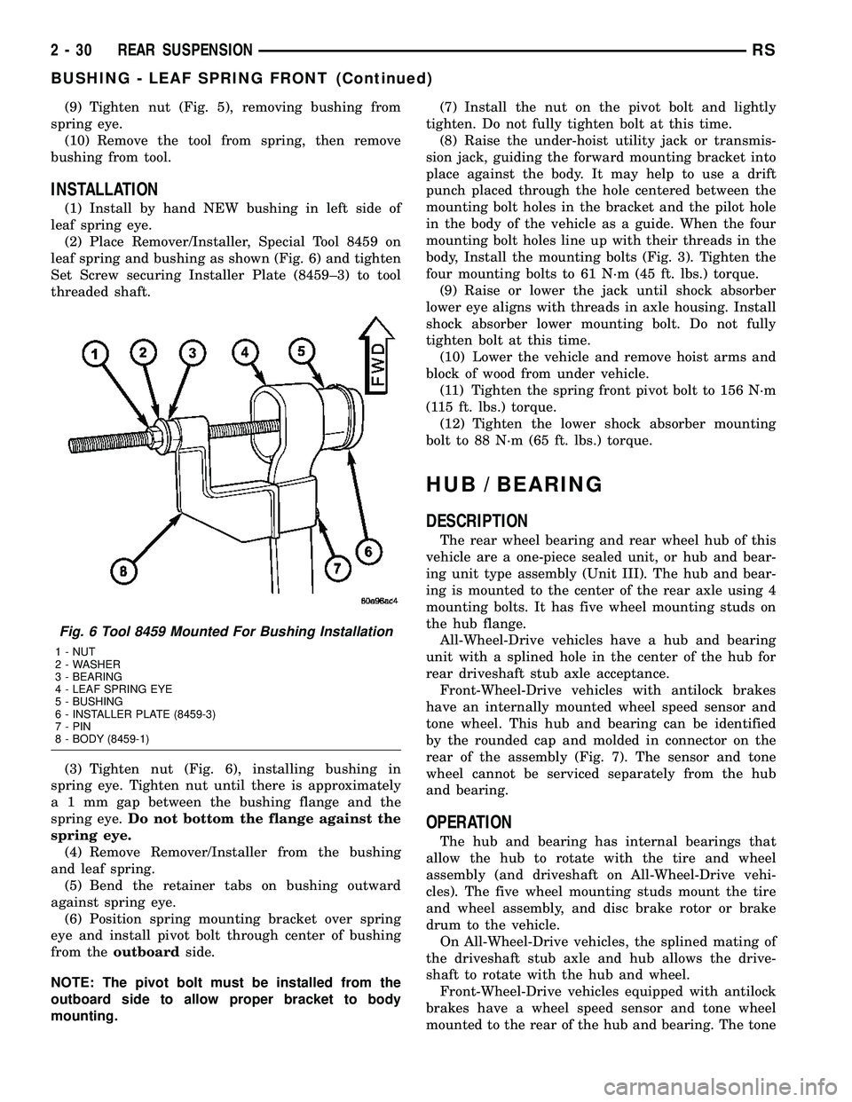
(2) Place Remover/Installer, Special Tool 8459 on
leaf spring and bushing as shown (Fig. 6) and tighten
Set Screw securing Installer Plate (8459±3) to tool
threaded shaft.
(3) Tighten nut (Fig. 6), installing bushing in
spring eye. Tighten nut until there is approximately
a 1 mm gap between the bushing flange and the
spring eye.Do not bottom the flange against the
spring eye.
(4) Remove Remover/Installer from the bushing
and leaf spring.
(5) Bend the retainer tabs on bushing outward
against spring eye.
(6) Position spring mounting bracket over spring
eye and install pivot bolt through center of bushing
from theoutboardside.
NOTE: The pivot bolt must be installed from the
outboard side to allow proper bracket to body
mounting.(7) Install the nut on the pivot bolt and lightly
tighten. Do not fully tighten bolt at this time.
(8) Raise the under-hoist utility jack or transmis-
sion jack, guiding the forward mounting bracket into
place against the body. It may help to use a drift
punch placed through the hole centered between the
mounting bolt holes in the bracket and the pilot hole
in the body of the vehicle as a guide. When the four
mounting bolt holes line up with their threads in the
body, Install the mounting bolts (Fig. 3). Tighten the
four mounting bolts to 61 N´m (45 ft. lbs.) torque.
(9) Raise or lower the jack until shock absorber
lower eye aligns with threads in axle housing. Install
shock absorber lower mounting bolt. Do not fully
tighten bolt at this time.
(10) Lower the vehicle and remove hoist arms and
block of wood from under vehicle.
(11) Tighten the spring front pivot bolt to 156 N´m
(115 ft. lbs.) torque.
(12) Tighten the lower shock absorber mounting
bolt to 88 N´m (65 ft. lbs.) torque.
HUB / BEARING
DESCRIPTION
The rear wheel bearing and rear wheel hub of this
vehicle are a one-piece sealed unit, or hub and bear-
ing unit type assembly (Unit III). The hub and bear-
ing is mounted to the center of the rear axle using 4
mounting bolts. It has five wheel mounting studs on
the hub flange.
All-Wheel-Drive vehicles have a hub and bearing
unit with a splined hole in the center of the hub for
rear driveshaft stub axle acceptance.
Front-Wheel-Drive vehicles with antilock brakes
have an internally mounted wheel speed sensor and
tone wheel. This hub and bearing can be identified
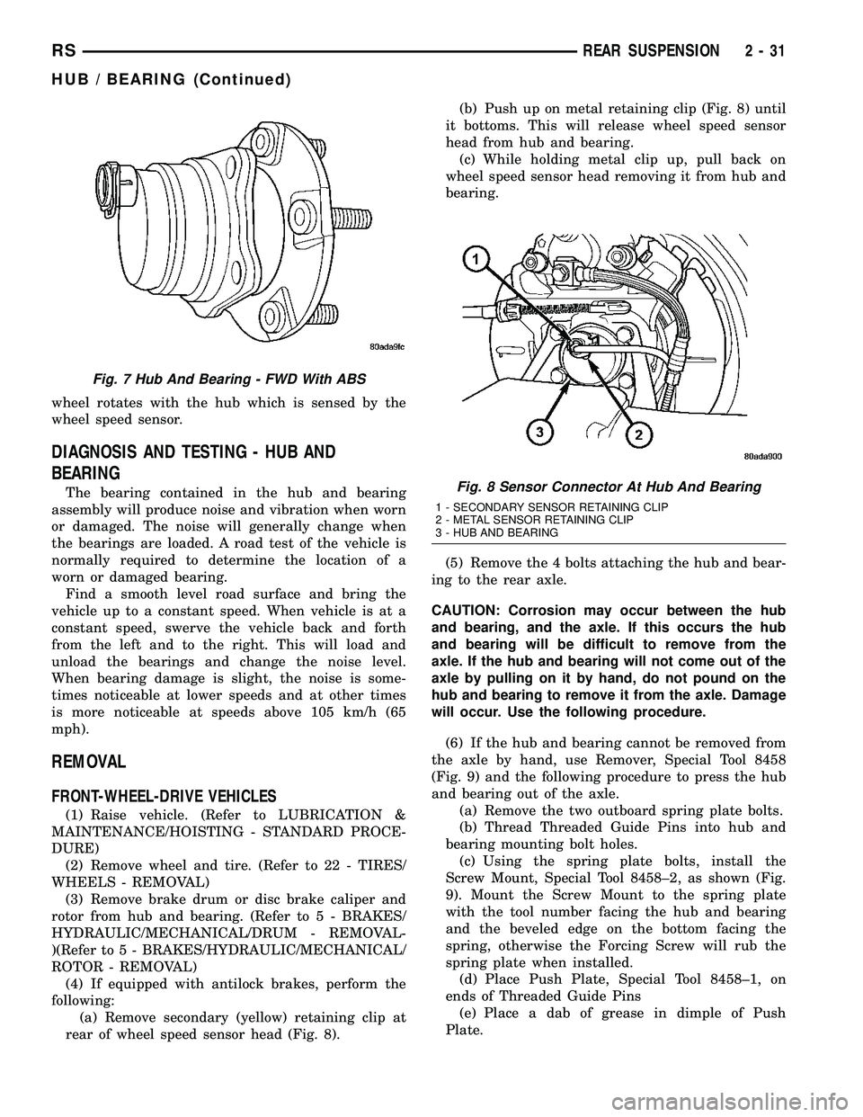
by the rounded cap and molded in connector on the
rear of the assembly (Fig. 7). The sensor and tone
wheel cannot be serviced separately from the hub
and bearing.
OPERATION
The hub and bearing has internal bearings that
allow the hub to rotate with the tire and wheel
assembly (and driveshaft on All-Wheel-Drive vehi-
cles). The five wheel mounting studs mount the tire
and wheel assembly, and disc brake rotor or brake
drum to the vehicle.
On All-Wheel-Drive vehicles, the splined mating of
the driveshaft stub axle and hub allows the drive-
shaft to rotate with the hub and wheel.
Front-Wheel-Drive vehicles equipped with antilock
brakes have a wheel speed sensor and tone wheel
mounted to the rear of the hub and bearing. The tone
Fig. 6 Tool 8459 Mounted For Bushing Installation
1 - NUT
2 - WASHER
3 - BEARING
4 - LEAF SPRING EYE
5 - BUSHING
6 - INSTALLER PLATE (8459-3)
7 - PIN
8 - BODY (8459-1)
2 - 30 REAR SUSPENSIONRS
BUSHING - LEAF SPRING FRONT (Continued)
Page 72 of 2339
wheel rotates with the hub which is sensed by the
wheel speed sensor.
DIAGNOSIS AND TESTING - HUB AND
BEARING
The bearing contained in the hub and bearing
assembly will produce noise and vibration when worn
or damaged. The noise will generally change when
the bearings are loaded. A road test of the vehicle is
normally required to determine the location of a
worn or damaged bearing.
Find a smooth level road surface and bring the
vehicle up to a constant speed. When vehicle is at a
constant speed, swerve the vehicle back and forth
from the left and to the right. This will load and
unload the bearings and change the noise level.
When bearing damage is slight, the noise is some-
times noticeable at lower speeds and at other times
is more noticeable at speeds above 105 km/h (65
mph).
REMOVAL
FRONT-WHEEL-DRIVE VEHICLES
(1) Raise vehicle. (Refer to LUBRICATION &
MAINTENANCE/HOISTING - STANDARD PROCE-
DURE)
(2) Remove wheel and tire. (Refer to 22 - TIRES/
WHEELS - REMOVAL)
(3) Remove brake drum or disc brake caliper and
rotor from hub and bearing. (Refer to 5 - BRAKES/
HYDRAULIC/MECHANICAL/DRUM - REMOVAL-
)(Refer to 5 - BRAKES/HYDRAULIC/MECHANICAL/
ROTOR - REMOVAL)
(4) If equipped with antilock brakes, perform the
following:
(a) Remove secondary (yellow) retaining clip at
rear of wheel speed sensor head (Fig. 8).(b) Push up on metal retaining clip (Fig. 8) until
it bottoms. This will release wheel speed sensor
head from hub and bearing.
(c) While holding metal clip up, pull back on
wheel speed sensor head removing it from hub and
bearing.
(5) Remove the 4 bolts attaching the hub and bear-
ing to the rear axle.
CAUTION: Corrosion may occur between the hub
and bearing, and the axle. If this occurs the hub
and bearing will be difficult to remove from the
axle. If the hub and bearing will not come out of the
axle by pulling on it by hand, do not pound on the
hub and bearing to remove it from the axle. Damage
will occur. Use the following procedure.
(6) If the hub and bearing cannot be removed from
the axle by hand, use Remover, Special Tool 8458
(Fig. 9) and the following procedure to press the hub
and bearing out of the axle.
(a) Remove the two outboard spring plate bolts.
(b) Thread Threaded Guide Pins into hub and
bearing mounting bolt holes.
(c) Using the spring plate bolts, install the
Screw Mount, Special Tool 8458±2, as shown (Fig.
9). Mount the Screw Mount to the spring plate
with the tool number facing the hub and bearing
and the beveled edge on the bottom facing the
spring, otherwise the Forcing Screw will rub the
spring plate when installed.
(d) Place Push Plate, Special Tool 8458±1, on
ends of Threaded Guide Pins
(e) Place a dab of grease in dimple of Push
Plate.
Fig. 7 Hub And Bearing - FWD With ABS
Fig. 8 Sensor Connector At Hub And Bearing
1 - SECONDARY SENSOR RETAINING CLIP
2 - METAL SENSOR RETAINING CLIP
3 - HUB AND BEARING
RSREAR SUSPENSION2-31
HUB / BEARING (Continued)