charging CHRYSLER CARAVAN 2005 Service Manual
[x] Cancel search | Manufacturer: CHRYSLER, Model Year: 2005, Model line: CARAVAN, Model: CHRYSLER CARAVAN 2005Pages: 2339, PDF Size: 59.69 MB
Page 6 of 2339
FASTENER USAGE
DESCRIPTION
FASTENER USAGE
WARNING: USE OF AN INCORRECT FASTENER
MAY RESULT IN COMPONENT DAMAGE OR PER-
SONAL INJURY.
Fasteners and torque specifications references in
this Service Manual are identified in metric and SAE
format.
During any maintenance or repair procedures, it is
important to salvage all fasteners (nuts, bolts, etc.)
for reassembly. If the fastener is not salvageable, a
fastener of equivalent specification must be used.
THREADED HOLE REPAIR
Most stripped threaded holes can be repaired using
a Helicoilt. Follow the vehicle or Helicoiltrecommen-
dations for application and repair procedures.
INTERNATIONAL SYMBOLS
DESCRIPTION
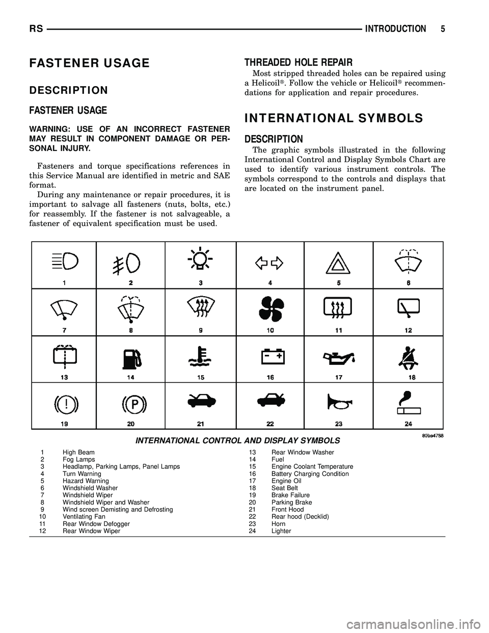
The graphic symbols illustrated in the following
International Control and Display Symbols Chart are
used to identify various instrument controls. The
symbols correspond to the controls and displays that
are located on the instrument panel.
INTERNATIONAL CONTROL AND DISPLAY SYMBOLS
1 High Beam 13 Rear Window Washer
2 Fog Lamps 14 Fuel
3 Headlamp, Parking Lamps, Panel Lamps 15 Engine Coolant Temperature
4 Turn Warning 16 Battery Charging Condition
5 Hazard Warning 17 Engine Oil
6 Windshield Washer 18 Seat Belt
7 Windshield Wiper 19 Brake Failure
8 Windshield Wiper and Washer 20 Parking Brake
9 Wind screen Demisting and Defrosting 21 Front Hood
10 Ventilating Fan 22 Rear hood (Decklid)
11 Rear Window Defogger 23 Horn
12 Rear Window Wiper 24 Lighter
RSINTRODUCTION5
Page 38 of 2339
JUMP STARTING
STANDARD PROCEDURE - JUMP STARTING
WARNING: REVIEW ALL SAFETY PRECAUTIONS
AND WARNINGS. (Refer to 8 - ELECTRICAL/BAT-
TERY SYSTEM/BATTERY - STANDARD PROCE-
DURE).
WARNING: DO NOT JUMP START A FROZEN BAT-
TERY, PERSONAL INJURY CAN RESULT.
WARNING: DO NOT JUMP START WHEN MAINTE-
NANCE FREE BATTERY INDICATOR DOT IS BRIGHT
COLOR.
WARNING: DO NOT ALLOW JUMPER CABLE
CLAMPS TO TOUCH EACH OTHER WHEN CON-
NECTED TO A BOOSTER SOURCE.
WARNING: DO NOT USE OPEN FLAME NEAR BAT-
TERYWARNING: REMOVE METALLIC JEWELRY WORN
ON HANDS OR WRISTS TO AVOID INJURY BY
ACCIDENTAL ARCING OF BATTERY CURRENT.
WARNING: WHEN USING A HIGH OUTPUT BOOST-
ING DEVICE, DO NOT ALLOW BATTERY VOLTAGE
TO EXCEED 16 VOLTS.
WARNING: REFER TO INSTRUCTIONS PROVIDED
WITH DEVICE BEING USED.
CAUTION: DO NOT ATTEMPT TO PUSH OR TOW
THE VEHICLE TO START IT. THE VEHICLE CANNOT
BE STARTED THIS WAY. PUSHING WITH ANOTHER
VEHICLE MAY DAMAGE THE TRANSAXLE OR THE
REAR OF THE VEHICLE.
(1) Raise hood on disabled vehicle and visually
inspect engine compartment for:
²Battery cable clamp condition, clean if necessary.
²Frozen battery.
²Clear or bright color test indicator, if equipped.
²Generator drive belt condition and tension.
²Fuel fumes or leakage, correct if necessary.
CAUTION: If the cause of starting problem on dis-
abled vehicle is severe, damage to booster vehicle
charging system can result.
(2) When using another vehicle as a booster
source, park the booster vehicle within cable reach.
Turn off all accessories, set the parking brake, place
the automatic transmission in PARK or the manual
transmission in NEUTRAL and turn the ignition
OFF.
(3) On disabled vehicle, place gear selector in park
or neutral and set park brake. Turn off all accesso-
ries.
(4) Connect jumper cables to booster battery. RED
clamp to positive terminal (+). BLACK clamp to neg-
ative terminal (-). DO NOT allow clamps at opposite
end of cables to touch, electrical arc will result.
Review all warnings in this procedure.
(5) On disabled vehicle, connect RED jumper cable
clamp to positive (+) terminal. Connect BLACK
jumper cable clamp to engine ground as close to the
ground cable attaching point as possible (Fig. 6).
(Refer to 8 - ELECTRICAL/BATTERY SYSTEM/BAT-
TERY - STANDARD PROCEDURE).
(6) Start the engine in the vehicle which has the
booster battery, let the engine idle a few minutes,
then start the engine in the vehicle with the dis-
charged battery.
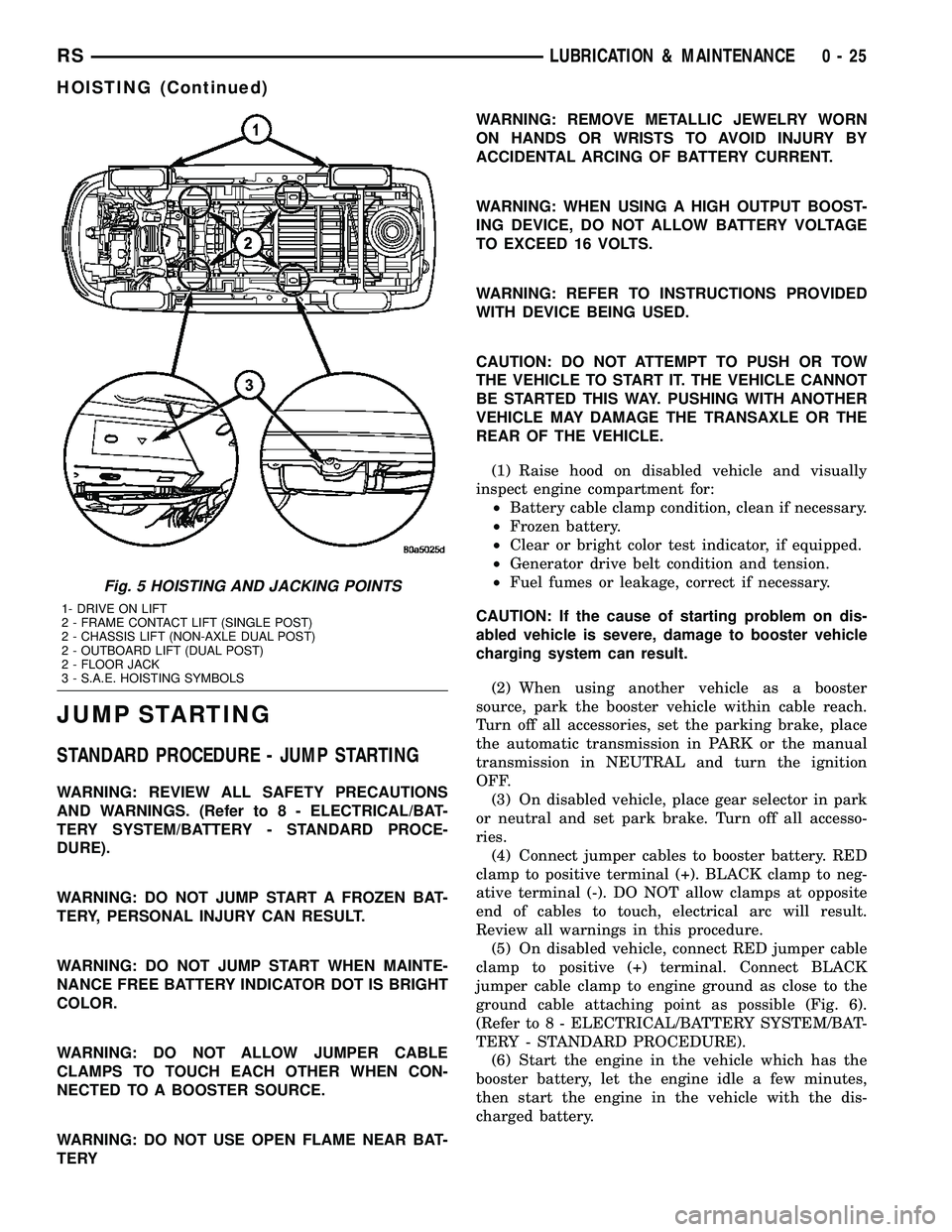
Fig. 5 HOISTING AND JACKING POINTS
1- DRIVE ON LIFT
2 - FRAME CONTACT LIFT (SINGLE POST)
2 - CHASSIS LIFT (NON-AXLE DUAL POST)
2 - OUTBOARD LIFT (DUAL POST)
2 - FLOOR JACK
3 - S.A.E. HOISTING SYMBOLS
RSLUBRICATION & MAINTENANCE0-25
HOISTING (Continued)
Page 274 of 2339
CAUTION: Pulling the antenna cable straight out of
the radio without pulling on the locking antenna
connector could damage the cable or radio.
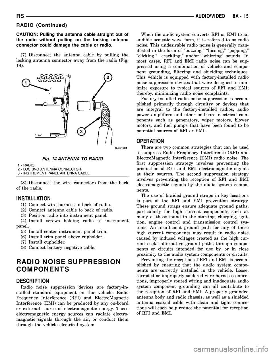
(7) Disconnect the antenna cable by pulling the
locking antenna connector away from the radio (Fig.
14).
(8) Disconnect the wire connectors from the back
of the radio.
INSTALLATION
(1) Connect wire harness to back of radio.
(2) Connect antenna cable to back of radio.
(3) Position radio into instrument panel.
(4) Install screws holding radio to instrument
panel.
(5) Install center instrument panel trim.
(6) Install trim panel above cupholder.
(7) Install cupholder.
(8) Connect battery negative cable.
RADIO NOISE SUPPRESSION
COMPONENTS
DESCRIPTION
Radio noise suppression devices are factory-in-
stalled standard equipment on this vehicle. Radio
Frequency Interference (RFI) and ElectroMagnetic
Interference (EMI) can be produced by any on-board
or external source of electromagnetic energy. These
electromagnetic energy sources can radiate electro-
magnetic signals through the air, or conduct them
through the vehicle electrical system.When the audio system converts RFI or EMI to an
audible acoustic wave form, it is referred to as radio
noise. This undesirable radio noise is generally man-
ifested in the form of ªbuzzing,º ªhissing,º ªpopping,º
ªclicking,º ªcrackling,º and/or ªwhirringº sounds. In
most cases, RFI and EMI radio noise can be sup-
pressed using a combination of vehicle and compo-
nent grounding, filtering and shielding techniques.
This vehicle is equipped with factory-installed radio
noise suppression devices that were designed to min-
imize exposure to typical sources of RFI and EMI;
thereby, minimizing radio noise complaints.
Factory-installed radio noise suppression is accom-
plished primarily through circuitry or devices that
are integral to the factory-installed radios, audio
power amplifiers and other on-board electrical com-
ponents such as generators, wiper motors, blower
motors, and fuel pumps that have been found to be
potential sources of RFI or EMI.
OPERATION
There are two common strategies that can be used
to suppress Radio Frequency Interference (RFI) and
ElectroMagnetic Interference (EMI) radio noise. The
first suppression strategy involves preventing the
production of RFI and EMI electromagnetic signals
at their sources. The second suppression strategy
involves preventing the reception of RFI and EMI
electromagnetic signals by the audio system compo-
nents.
The use of braided ground straps in key locations
is part of the RFI and EMI prevention strategy.
These ground straps ensure adequate ground paths,
particularly for high current components such as
many of those found in the starting, charging, igni-
tion, engine control and transmission control sys-
tems. An insufficient ground path for any of these
high current components may result in radio noise
caused by induced voltages created as the high cur-
rent seeks alternative ground paths through compo-
nents or circuits intended for use by, or in close
proximity to the audio system components or circuits.
Preventing the reception of RFI and EMI is accom-
plished by ensuring that the audio system compo-
nents are correctly installed in the vehicle. Loose,
corroded or improperly soldered wire harness connec-
tions, improperly routed wiring and inadequate audio
system component grounding can all contribute to
the reception of RFI and EMI. A properly grounded
antenna body and radio chassis, as well as a shielded
antenna coaxial cable with clean and tight connec-
tions will each help reduce the potential for reception
of RFI and EMI.
Fig. 14 ANTENNA TO RADIO
1 - RADIO
2 - LOCKING ANTENNA CONNECTOR
3 - INSTRUMENT PANEL ANTENNA CABLE
RSAUDIO/VIDEO8A-15
RADIO (Continued)
Page 306 of 2339
ENGINE SYSTEMS
TABLE OF CONTENTS
page page
BATTERY SYSTEM......................... 1
CHARGING.............................. 21STARTING............................... 31
BATTERY SYSTEM
TABLE OF CONTENTS
page page
BATTERY SYSTEM
DESCRIPTION..........................1
OPERATION............................2
DIAGNOSIS AND TESTING
BATTERY SYSTEM.....................2
CLEANING.............................5
INSPECTION...........................5
SPECIFICATIONS
BATTERY............................6
SPECIAL TOOLS
BATTERY SYSTEM SPECIAL TOOLS.......7
BATTERY
DESCRIPTION..........................7
OPERATION............................9
DIAGNOSIS AND TESTING
BATTERY............................9
STANDARD PROCEDURE
SPIRAL PLATE BATTERY CHARGING......10
CONVENTIONAL BATTERY CHARGING....11
OPEN-CIRCUIT VOLTAGE TEST..........13IGNITION-OFF DRAW TEST.............13
CHECKING BATTERY ELECTROLYTE
LEVEL..............................14
MICRO 420 BATTERY TESTER...........15
REMOVAL - BATTERY...................16
INSTALLATION.........................16
BATTERY HOLDDOWN
REMOVAL.............................16
INSTALLATION.........................16
BATTERY CABLES
DESCRIPTION.........................16
OPERATION...........................17
DIAGNOSIS AND TESTING
BATTERY CABLES....................17
REMOVAL.............................19
INSTALLATION.........................19
BATTERY TRAY
DESCRIPTION.........................19
REMOVAL.............................19
INSTALLATION.........................20
BATTERY SYSTEM
DESCRIPTION
This vehicle is equipped with a single 12-volt bat-
tery. All of the components of the battery system are
located within the engine compartment. The battery
system for this vehicle contains the following related
components:
²Battery- The storage battery provides a reli-
able means of storing a renewable source of electrical
energy within the vehicle.
²Battery Cable- The battery cables connect the
battery terminal posts to the vehicle electrical sys-
tem.²Battery Holddown- The battery holddown
hardware secures the battery in the battery tray in
the engine compartment.
²Battery Thermowrap- The battery thermow-
rap insulates the battery to protect it from engine
compartment temperature extremes.
²Battery Tray- The battery tray provides a
secure mounting location in the vehicle for the bat-
tery and an anchor point for the battery holddown
hardware.
RSENGINE SYSTEMS8F-1
Page 307 of 2339

OPERATION
The battery system is designed to provide a safe,
efficient, reliable and mobile means of delivering and
storing electrical energy. This electrical energy is
required to operate the engine starting system, as
well as to operate many of the other vehicle acces-
sory systems for limited durations while the engine
and/or the charging system are not operating. The
battery system is also designed to provide a reserve
of electrical energy to supplement the charging sys-
tem for short durations while the engine is running
and the electrical current demands of the vehicle
exceed the output of the charging system. In addition
to delivering, and storing electrical energy for the
vehicle, the battery system serves as a capacitor and
voltage stabilizer for the vehicle electrical system. It
absorbs most abnormal or transient voltages caused
by the switching of any of the electrical components
or circuits in the vehicle.
DIAGNOSIS AND TESTING
BATTERY SYSTEM
The battery, starting, and charging systems in the
vehicle operate with one another and must be tested
as a complete system. In order for the engine to start
and the battery to maintain its charge properly, all of
the components that are used in these systems must
perform within specifications. It is important that
the battery, starting, and charging systems be thor-
oughly tested and inspected any time a battery needs
to be charged or replaced. The cause of abnormal bat-
tery discharge, overcharging or early battery failuremust be diagnosed and corrected before a battery is
replaced and before a vehicle is returned to service.
The service information for these systems has been
separated within this service manual to make it eas-
ier to locate the specific information you are seeking.
However, when attempting to diagnose any of these
systems, it is important that you keep their interde-
pendency in mind.
The diagnostic procedures used for the battery,
starting, and charging systems include the most
basic conventional diagnostic methods, to the more
sophisticated On-Board Diagnostics (OBD) built into
the Powertrain Control Module (PCM). Use of an
induction-type milliampere ammeter, a volt/ohmme-
ter, a battery charger, a carbon pile rheostat (load
tester) and a 12-volt test lamp may be required. All
OBD-sensed systems are monitored by the PCM.
Each monitored circuit is assigned a Diagnostic Trou-
ble Code (DTC). The PCM will store a DTC in elec-
tronic memory for any failure it detects. (Refer to 8 -
ELECTRICAL/CHARGING - DIAGNOSIS AND
TESTING) for the proper charging system on-board
diagnostic test procedures.MICRO 420 BATTERY TESTER
The Micro 420 automotive battery tester is
designed to help the dealership technicians diagnose
the cause of a defective battery. Follow the instruc-
tion manual supplied with the tester to properly
diagnose a vehicle. If the instruction manual is not
available refer to the standard procedure in this sec-
tion, which includes the directions for using the
Micro 420 battery tester.
8F - 2 BATTERY SYSTEMRS
BATTERY SYSTEM (Continued)
Page 308 of 2339

BATTERY SYSTEM DIAGNOSIS
CONDITION POSSIBLE CAUSES CORRECTION
THE BATTERY SEEMS
WEAK OR DEAD WHEN
ATTEMPTING TO START
THE ENGINE.1. The electrical system
ignition-off draw is excessive.1. (Refer to 8 - ELECTRICAL/BATTERY
SYSTEM/BATTERY - STANDARD PROCEDURE
- IGNITION-OFF DRAW TEST) for the proper test
procedures. Repair the excessive ignition-off
draw, as required.
2. The charging system is
inoperative.2. Determine if the charging system is performing
to specifications. (Refer to 8 - ELECTRICAL/
CHARGING - DIAGNOSIS AND TESTING) for
additional charging system diagnosis and testing
procedures. Repair the inoperative charging
system, as required.
3. The battery is discharged. 3. Determine the battery state-of-charge using the
Micro 420 battery tester. Refer to the Standard
Procedures in this section for additional test
procedures. Charge the inoperative battery, as
required.
4. The battery terminal
connections are loose or
corroded.4. (Refer to 8 - ELECTRICAL/BATTERY
SYSTEM/CABLES - DIAGNOSIS AND TESTING)
for the proper battery cable diagnosis and testing
procedures. Clean and tighten the battery
terminal connections, as required.
5. The battery has an
incorrect size or rating for
this vehicle.5. (Refer to 8 - ELECTRICAL/BATTERY SYSTEM
- SPECIFICATIONS) for the proper size and
rating. Replace an incorrect battery, as required.
6. The battery is inoperative. 6. Test the battery using the Micro 420 battery
tester. Refer to the Standard Procedures in this
section for additional test procedures. Replace
the inoperative battery, as required.
7. The starting system is
inoperative.7. Determine if the starting system is performing
to specifications. (Refer to 8 - ELECTRICAL/
STARTING - DIAGNOSIS AND TESTING) for the
proper starting system diagnosis and testing
procedures. Repair the inoperative starting
system, as required.
8. The battery is physically
damaged.8. Inspect the battery for loose terminal posts or a
cracked and leaking case. Replace the damaged
battery, as required.
RSBATTERY SYSTEM8F-3
BATTERY SYSTEM (Continued)
Page 309 of 2339
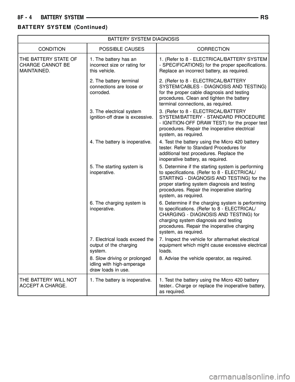
BATTERY SYSTEM DIAGNOSIS
CONDITION POSSIBLE CAUSES CORRECTION
THE BATTERY STATE OF
CHARGE CANNOT BE
MAINTAINED.1. The battery has an
incorrect size or rating for
this vehicle.1. (Refer to 8 - ELECTRICAL/BATTERY SYSTEM
- SPECIFICATIONS) for the proper specifications.
Replace an incorrect battery, as required.
2. The battery terminal
connections are loose or
corroded.2. (Refer to 8 - ELECTRICAL/BATTERY
SYSTEM/CABLES - DIAGNOSIS AND TESTING)
for the proper cable diagnosis and testing
procedures. Clean and tighten the battery
terminal connections, as required.
3. The electrical system
ignition-off draw is excessive.3. (Refer to 8 - ELECTRICAL/BATTERY
SYSTEM/BATTERY - STANDARD PROCEDURE
- IGNITION-OFF DRAW TEST) for the proper test
procedures. Repair the inoperative electrical
system, as required.
4. The battery is inoperative. 4. Test the battery using the Micro 420 battery
tester. Refer to Standard Procedures for
additional test procedures. Replace the
inoperative battery, as required.
5. The starting system is
inoperative.5. Determine if the starting system is performing
to specifications. (Refer to 8 - ELECTRICAL/
STARTING - DIAGNOSIS AND TESTING) for the
proper starting system diagnosis and testing
procedures. Repair the inoperative starting
system, as required.
6. The charging system is
inoperative.6. Determine if the charging system is performing
to specifications. (Refer to 8 - ELECTRICAL/
CHARGING - DIAGNOSIS AND TESTING) for
charging system diagnosis and testing
procedures. Repair the inoperative charging
system, as required.
7. Electrical loads exceed the
output of the charging
system.7. Inspect the vehicle for aftermarket electrical
equipment which might cause excessive electrical
loads.
8. Slow driving or prolonged
idling with high-amperage
draw loads in use.8. Advise the vehicle operator, as required.
THE BATTERY WILL NOT
ACCEPT A CHARGE.1. The battery is inoperative. 1. Test the battery using the Micro 420 battery
tester.. Charge or replace the inoperative battery,
as required.
8F - 4 BATTERY SYSTEMRS
BATTERY SYSTEM (Continued)
Page 311 of 2339
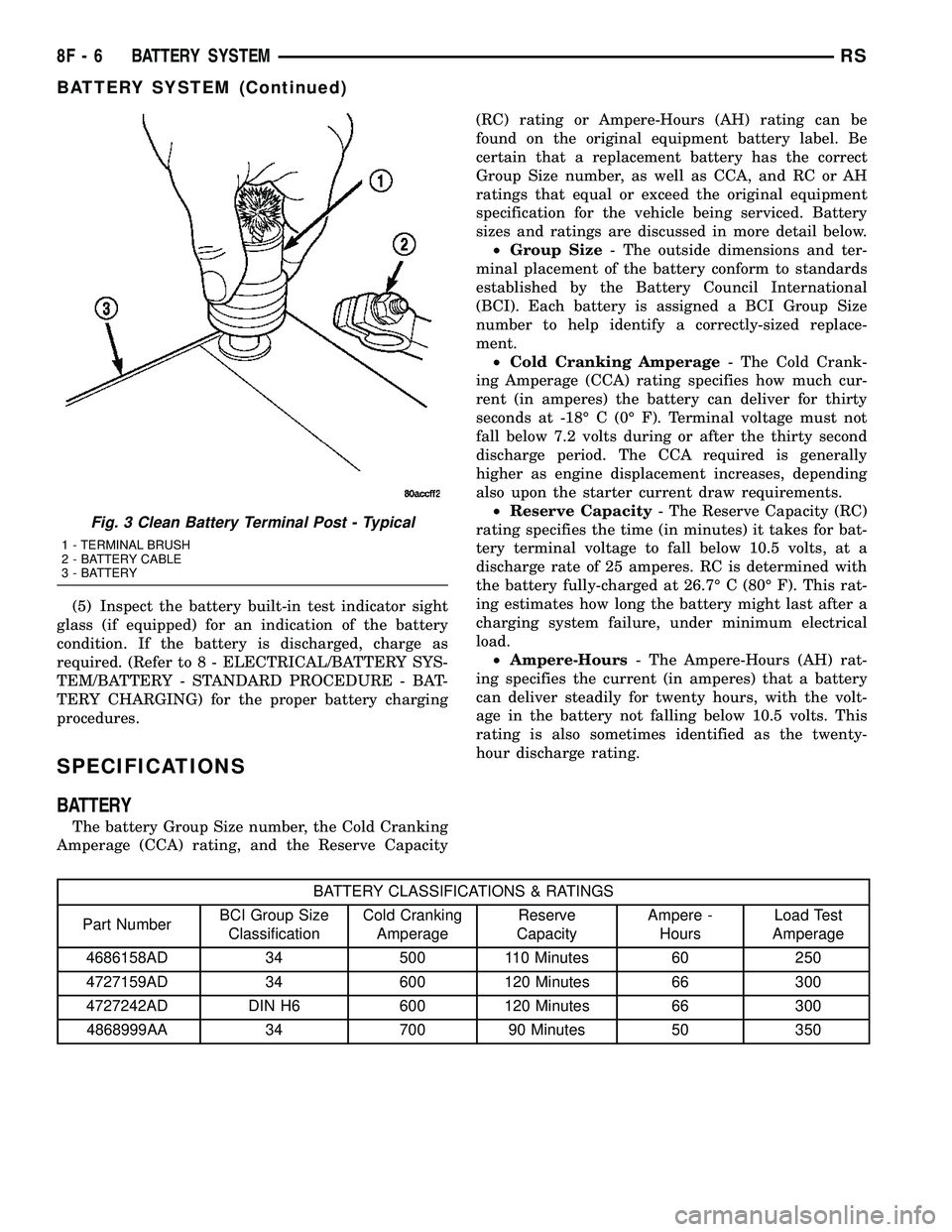
(5) Inspect the battery built-in test indicator sight
glass (if equipped) for an indication of the battery
condition. If the battery is discharged, charge as
required. (Refer to 8 - ELECTRICAL/BATTERY SYS-
TEM/BATTERY - STANDARD PROCEDURE - BAT-
TERY CHARGING) for the proper battery charging
procedures.
SPECIFICATIONS
BATTERY
The battery Group Size number, the Cold Cranking
Amperage (CCA) rating, and the Reserve Capacity(RC) rating or Ampere-Hours (AH) rating can be
found on the original equipment battery label. Be
certain that a replacement battery has the correct
Group Size number, as well as CCA, and RC or AH
ratings that equal or exceed the original equipment
specification for the vehicle being serviced. Battery
sizes and ratings are discussed in more detail below.
²Group Size- The outside dimensions and ter-
minal placement of the battery conform to standards
established by the Battery Council International
(BCI). Each battery is assigned a BCI Group Size
number to help identify a correctly-sized replace-
ment.
²Cold Cranking Amperage- The Cold Crank-
ing Amperage (CCA) rating specifies how much cur-
rent (in amperes) the battery can deliver for thirty
seconds at -18É C (0É F). Terminal voltage must not
fall below 7.2 volts during or after the thirty second
discharge period. The CCA required is generally
higher as engine displacement increases, depending
also upon the starter current draw requirements.
²Reserve Capacity- The Reserve Capacity (RC)
rating specifies the time (in minutes) it takes for bat-
tery terminal voltage to fall below 10.5 volts, at a
discharge rate of 25 amperes. RC is determined with
the battery fully-charged at 26.7É C (80É F). This rat-
ing estimates how long the battery might last after a
charging system failure, under minimum electrical
load.
²Ampere-Hours- The Ampere-Hours (AH) rat-
ing specifies the current (in amperes) that a battery
can deliver steadily for twenty hours, with the volt-
age in the battery not falling below 10.5 volts. This
rating is also sometimes identified as the twenty-
hour discharge rating.
BATTERY CLASSIFICATIONS & RATINGS
Part NumberBCI Group Size
ClassificationCold Cranking
AmperageReserve
CapacityAmpere -
HoursLoad Test
Amperage
4686158AD 34 500 110 Minutes 60 250
4727159AD 34 600 120 Minutes 66 300
4727242AD DIN H6 600 120 Minutes 66 300
4868999AA 34 700 90 Minutes 50 350
Fig. 3 Clean Battery Terminal Post - Typical
1 - TERMINAL BRUSH
2 - BATTERY CABLE
3 - BATTERY
8F - 6 BATTERY SYSTEMRS
BATTERY SYSTEM (Continued)
Page 312 of 2339

SPECIAL TOOLS
BATTERY SYSTEM SPECIAL TOOLS
BATTERY
DESCRIPTION
There are three different batteries available for
this vehicle. Vehicles equipped with a diesel engine
utilize a spiral wound plate designed battery with
recombination technology. This is a maintenance-free
battery that is capable of delivering more power than
a conventional battery. This additional power is
required by a diesel engine during cold cranking.
Vehicles equipped with a gasoline engine utilize a
conventional battery. Refer to the following informa-
tion for detailed differences and descriptions of these
batteries.
SPIRAL PLATE BATTERY - DIESEL ENGINE
By tightly winding layers of spiral grids and acid-
permeated vitreous separators into cells, the battery
has more power and service life than conventional
batteries of the same size. The spiral plate battery is
permanently sealed. Through gas recombination,
hydrogen and oxygen within the battery are captured
during normal charging and reunited to form thewater within the electrolyte, eliminating the need to
add distilled water. Therefore, these batteries have
non-removable battery vent caps (Fig. 4).
The acid inside a spiral plate battery is bound
within the vitreous separators, ending the threat of
acid leaks. This feature allows the battery to be
installed in any position anywhere in the vehicle.
Spiral plate technology is the process by which the
plates holding the active material in the battery are
wound tightly in coils instead of hanging flat, like
conventional batteries. This design has a lower inter-
nal resistance and also increases the active material
surface area.
WARNING: NEVER EXCEED 14.4 VOLTS WHEN
CHARGING A SPIRAL PLATE BATTERY. PERSONAL
INJURY AND/OR BATTERY DAMAGE MAY RESULT.
Due to the maintanance-free design, distilled water
cannot be added to this battery. Therefore, if more
than 14.4 volts are used during the spiral plate bat-
tery charging process, water vapor can be exhausted
through the pressure-sensitive battery vents and lost
for good. This can permanently damage the spiral
plate battery.
Micro 420 Battery Tester
Fig. 4 MAINTENANCE-FREE DIESEL ENGINE
BATTERY
RSBATTERY SYSTEM8F-7
BATTERY SYSTEM (Continued)
Page 313 of 2339

CONVENTIONAL BATTERY - GASOLINE ENGINE
Low-maintenance batteriesare used on export
vehicles equipped with a gasoline engine, these bat-
teries have removable battery cell caps (Fig. 5).
Watercanbe added to this battery. Under normal
service, the composition of this battery reduces gas-
sing and water loss at normal charge rates. However
these batteries may require additional distilled water
after years of service.
Maintenance-free batteriesare standard facto-
ry-installed equipment on all domestic vehicles. Male
post type terminals made of a soft lead material pro-
trude from the top of the molded plastic battery case
(Fig. 6)to provide the means for connecting the bat-
tery to the vehicle electrical system. The battery pos-
itive terminal post is visibly larger in diameter than
the negative terminal post, for easy identification.
The lettersPOSandNEGare also molded into the
top of the battery case adjacent to their respective
positive and negative terminal posts for additional
identification confirmation.
This battery is designed to provide a safe, efficient
and reliable means of storing electrical energy in a
chemical form. This means of energy storage allows
the battery to produce the electrical energy required
to operate the engine starting system, as well as to
operate many of the other vehicle accessory systems
for limited durations while the engine and/or thecharging system are not operating. The battery is
made up of six individual cells that are connected in
series. Each cell contains positively charged plate
groups that are connected with lead straps to the
positive terminal post, and negatively charged plate
groups that are connected with lead straps to the
negative terminal post. Each plate consists of a stiff
mesh framework or grid coated with lead dioxide
(positive plate) or sponge lead (negative plate). Insu-
lators or plate separators made of a non-conductive
material are inserted between the positive and nega-
tive plates to prevent them from contacting or short-
ing against one another. These dissimilar metal
plates are submerged in a sulfuric acid and water
solution called an electrolyte.
Some factory-installed batteries have a built-in test
indicator (hydrometer). The color visible in the sight
glass of the indicator will reveal the battery condi-
tion. For more information on the use of the built-in
test indicator, refer toStandard Procedures. The
chemical composition of the metal coated plates
within the low-maintenance battery used in export
models reduces battery gassing and water loss at
normal charge and discharge rates. Therefore, the
battery should not require additional water in nor-
mal service. If the electrolyte level in this battery
does become low, distilled water must be added. How-
ever, rapid loss of electrolyte can be caused by an
overcharging condition. Be certain to diagnose the
charging system after replenishing the water in the
Fig. 5 BATTERY CELL CAP REMOVAL/
INSTALLATION - LOW-MAINTANANCE GASOLINE
ENGINE BATTERY - EXPORT
1 - BATTERY CELL CAP
2 - BATTERY CASE
Fig. 6 Maintenance-Free Battery - Domestic
1 - POSITIVE POST
2 - VENT
3 - CELL CAP
4 - VENT
5 - CELL CAP
6 - VENT
7 - NEGATIVE POST
8 - INDICATOR EYE (if equipped)
9 - ELECTROLYTE LEVEL
10 - PLATE GROUPS
11 - MAINTENANCE-FREE BATTERY
8F - 8 BATTERY SYSTEMRS
BATTERY (Continued)