tow bar CHRYSLER CARAVAN 2005 Service Manual
[x] Cancel search | Manufacturer: CHRYSLER, Model Year: 2005, Model line: CARAVAN, Model: CHRYSLER CARAVAN 2005Pages: 2339, PDF Size: 59.69 MB
Page 39 of 2339
CAUTION: Do not crank starter motor on disabled
vehicle for more than 15 seconds, starter may over-
heat and could fail.
(7) If engine does not start within 15 seconds, stop
cranking engine and allow starter to cool (15 min-
utes), before cranking again.
DISCONNECT CABLE CLAMPS AS FOLLOWS:
²Disconnect BLACK cable clamp from engine
ground on disabled vehicle.
²When using a Booster vehicle, disconnect
BLACK cable clamp from battery negative terminal.
Disconnect RED cable clamp from battery positive
terminal.
²Disconnect RED cable clamp from battery posi-
tive terminal on disabled vehicle.
TOWING
STANDARD PROCEDURE - TOWING
WARNINGS AND CAUTIONS
WARNING: DO NOT ALLOW TOWING ATTACHMENT
DEVICES TO CONTACT THE FUEL TANK OR LINES,
FUEL LEAK CAN RESULT.
DO NOT LIFT OR TOW VEHICLE BY FRONT OR
REAR BUMPER.
DO NOT GO UNDER A LIFTED VEHICLE IF NOT
SUPPORTED PROPERLY ON SAFETY STANDS.
DO NOT ALLOW PASSENGERS TO RIDE IN A
TOWED VEHICLE.USE A SAFETY CHAIN THAT IS INDEPENDENT
FROM THE TOWING ATTACHMENT DEVICE.
CAUTION: Do not damage brake lines, exhaust sys-
tem, shock absorbers, sway bars, or any other
under vehicle components when attaching towing
device to vehicle.
Do not secure vehicle to towing device by the use
of front or rear suspension or steering components.
Remove or secure loose or protruding objects from
a damaged vehicle before towing.
Refer to state and local rules and regulations before
towing a vehicle.
Do not allow weight of towed vehicle to bear on
lower fascia, air dams, or spoilers.
RECOMMENDED TOWING EQUIPMENT
To avoid damage to bumper fascia and air dams
use:
²FWD vehicles, use of a flat bed towing device or
a wheel lift is recommended (Fig. 7).
²AWD vehicles, a flat bed towing device or a
wheel lift and towing dolly is recommended (Fig. 7).
When using a wheel lift towing device, be sure the
disabled vehicle has at least 100 mm (4 in.) ground
clearance. If minimum ground clearance cannot be
reached, use a towing dolly. If a flat bed device is
used, the approach angle should not exceed 15
degrees.
GROUND CLEARANCE
CAUTION: If vehicle is towed with wheels removed,
install lug nuts to retain brake drums or rotors.
A towed vehicle should be raised until the lifted
wheels are a minimum 100 mm (4 in.) from the
ground. Be sure there is at least 100 mm (4 in.)
clearance between the tail pipe and the ground. If
necessary, remove the wheels from the front end of
the vehicle and lower the front end closer to the
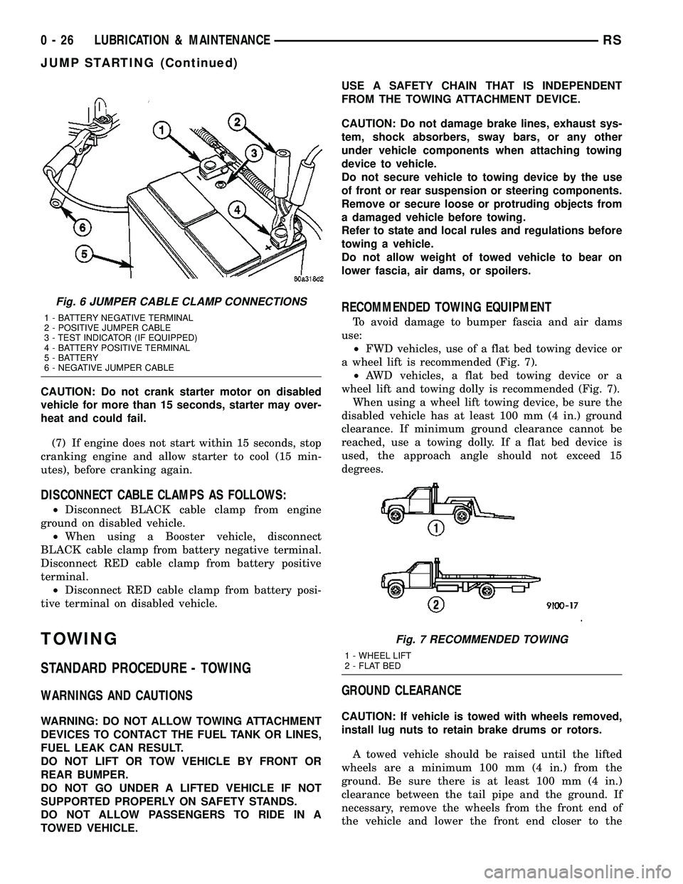
Fig. 6 JUMPER CABLE CLAMP CONNECTIONS
1 - BATTERY NEGATIVE TERMINAL
2 - POSITIVE JUMPER CABLE
3 - TEST INDICATOR (IF EQUIPPED)
4 - BATTERY POSITIVE TERMINAL
5 - BATTERY
6 - NEGATIVE JUMPER CABLE
Fig. 7 RECOMMENDED TOWING
1 - WHEEL LIFT
2 - FLAT BED
0 - 26 LUBRICATION & MAINTENANCERS
JUMP STARTING (Continued)
Page 40 of 2339
ground, to increase the ground clearance at the rear
of the vehicle. Install lug nuts on wheel attaching
studs to retain brake drums or rotors.
LOCKED VEHICLE TOWING
When a locked vehicle must be towed with the
front wheels on the ground, use a towing dolly or flat
bed hauler.
FLAT TOWING WITH TOW BAR
²Three speed automatic transaxle vehicles can be
flat towed at speeds not to exceed 40 km/h (25 mph)
for not more than 25 km (15 miles). The steering col-
umn must be unlocked and gear selector in neutral.
²Four speed electronic automatic transaxle vehi-
cles can be flat towed at speeds not to exceed 72
km/h (44 mph) for not more than 160 km (100 miles).
The steering column must be unlocked and gear
selector in neutral.
²AWD models should not be flat towed. For addi-
tional information, refer toRECOMMENDED TOW-
ING EQUIPMENTin this section.
FLAT BED TOWING TIE DOWNS
CAUTION: Do not tie vehicle down by attaching
chains or cables to suspension components or
engine mounts, damage to vehicle can result.
The vehicle can be tied to a flat bed device using
the two pair of front slots on the bottom surface of
the rails, behind the front wheels. The two pair of
rear slots on the bottom of the rail between thebumper extension bolts and on the bottom of the rail
just rearward of the jounce bumper. Vehicles
equipped with a rear sway bar have brackets at this
location.
TOWING ± FRONT WHEEL LIFT
If the vehicle is being towed from the front, when-
ever possible ensure at least 10 inches road clearance
to the tires.
TOWING ± REAR WHEEL LIFT
If a vehicle cannot be towed with the front wheels
lifted, the rear wheels can be lifted provided the fol-
lowing guide lines are observed.
CAUTION: Do not use steering column lock to
secure steering wheel during towing operation.
²On AWD vehicles, all four wheels must be free to
rotate. Use towing dollies at unlifted end of vehicle.
²Unlock steering column and secure steering
wheel in straight ahead position with a clamp device
designed for towing.
²Three speed automatic transaxle vehicles can be
flat towed at speeds not to exceed 40 km/h (25 mph)
for not more than 25 km (15 miles). The steering col-
umn must be unlocked and gear selector in neutral.
²Four speed electronic automatic transaxle vehi-
cles can be flat towed at speeds not to exceed 72
km/h (44 mph) for not more than 160 km (100 miles).
The steering column must be unlocked and gear
selector in neutral.
RSLUBRICATION & MAINTENANCE0-27
TOWING (Continued)
Page 43 of 2339
FRONT SUSPENSION
DESCRIPTION - FRONT SUSPENSION
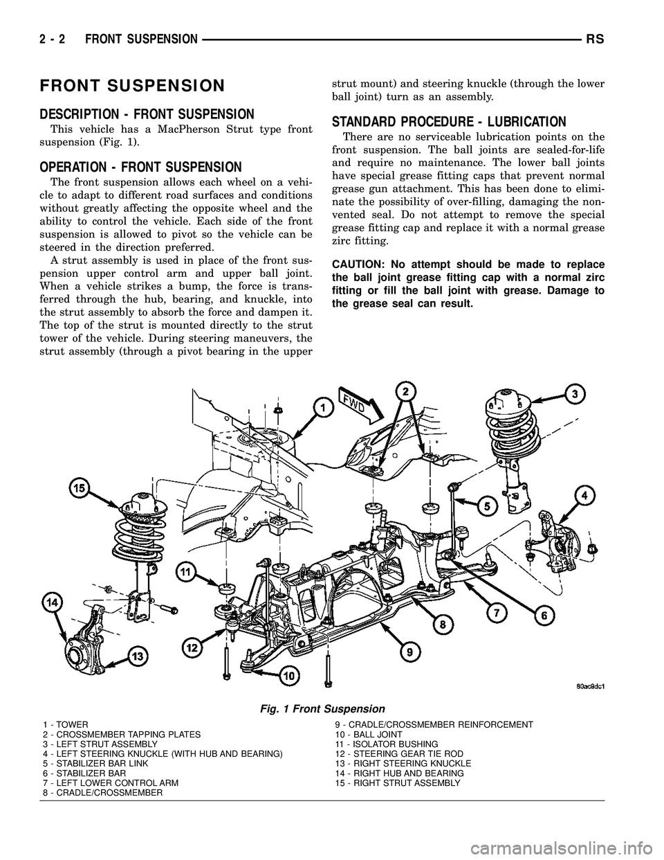
This vehicle has a MacPherson Strut type front
suspension (Fig. 1).
OPERATION - FRONT SUSPENSION
The front suspension allows each wheel on a vehi-
cle to adapt to different road surfaces and conditions
without greatly affecting the opposite wheel and the
ability to control the vehicle. Each side of the front
suspension is allowed to pivot so the vehicle can be
steered in the direction preferred.
A strut assembly is used in place of the front sus-
pension upper control arm and upper ball joint.
When a vehicle strikes a bump, the force is trans-
ferred through the hub, bearing, and knuckle, into
the strut assembly to absorb the force and dampen it.
The top of the strut is mounted directly to the strut
tower of the vehicle. During steering maneuvers, the
strut assembly (through a pivot bearing in the upperstrut mount) and steering knuckle (through the lower
ball joint) turn as an assembly.
STANDARD PROCEDURE - LUBRICATION
There are no serviceable lubrication points on the
front suspension. The ball joints are sealed-for-life
and require no maintenance. The lower ball joints
have special grease fitting caps that prevent normal
grease gun attachment. This has been done to elimi-
nate the possibility of over-filling, damaging the non-
vented seal. Do not attempt to remove the special
grease fitting cap and replace it with a normal grease
zirc fitting.
CAUTION: No attempt should be made to replace
the ball joint grease fitting cap with a normal zirc
fitting or fill the ball joint with grease. Damage to
the grease seal can result.
Fig. 1 Front Suspension
1 - TOWER
2 - CROSSMEMBER TAPPING PLATES
3 - LEFT STRUT ASSEMBLY
4 - LEFT STEERING KNUCKLE (WITH HUB AND BEARING)
5 - STABILIZER BAR LINK
6 - STABILIZER BAR
7 - LEFT LOWER CONTROL ARM
8 - CRADLE/CROSSMEMBER9 - CRADLE/CROSSMEMBER REINFORCEMENT
10 - BALL JOINT
11 - ISOLATOR BUSHING
12 - STEERING GEAR TIE ROD
13 - RIGHT STEERING KNUCKLE
14 - RIGHT HUB AND BEARING
15 - RIGHT STRUT ASSEMBLY
2 - 2 FRONT SUSPENSIONRS
Page 44 of 2339
SPECIFICATIONS
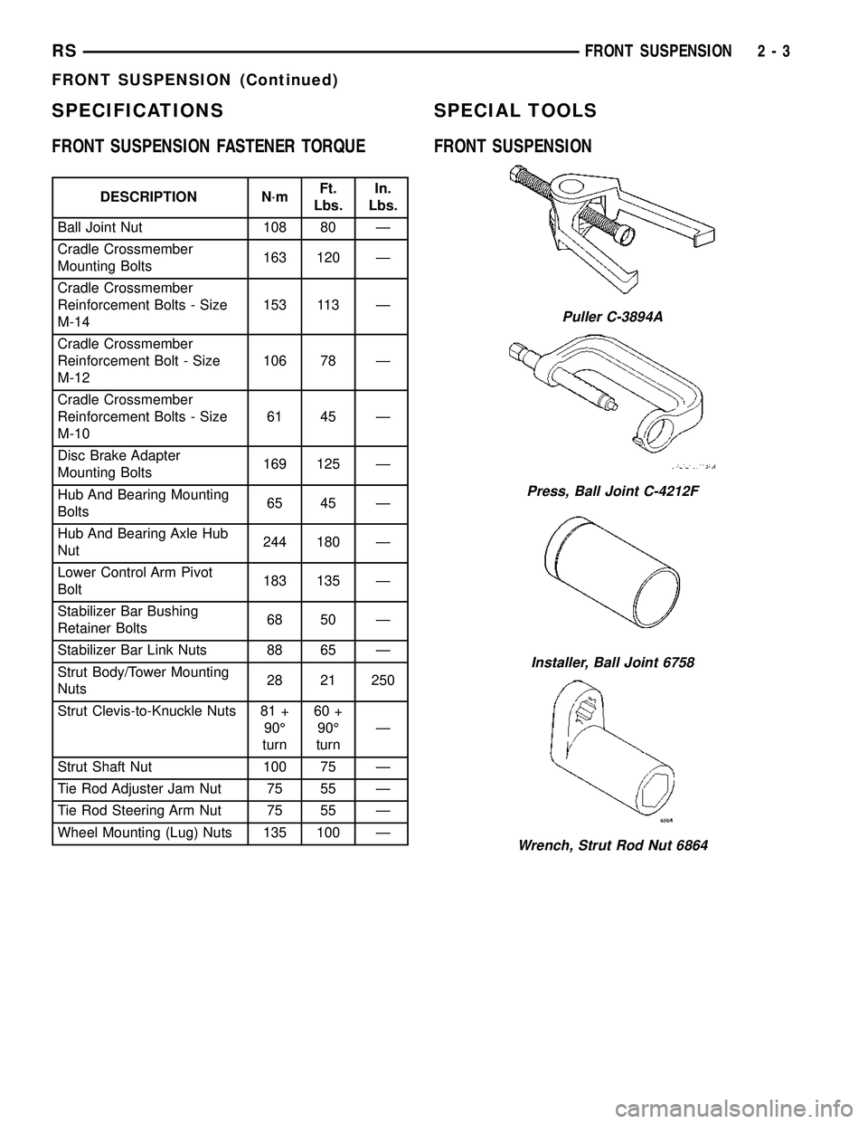
FRONT SUSPENSION FASTENER TORQUE
DESCRIPTION N´mFt.
Lbs.In.
Lbs.
Ball Joint Nut 108 80 Ð
Cradle Crossmember
Mounting Bolts163 120 Ð
Cradle Crossmember
Reinforcement Bolts - Size
M-14153 113 Ð
Cradle Crossmember
Reinforcement Bolt - Size
M-12106 78 Ð
Cradle Crossmember
Reinforcement Bolts - Size
M-1061 45 Ð
Disc Brake Adapter
Mounting Bolts169 125 Ð
Hub And Bearing Mounting
Bolts65 45 Ð
Hub And Bearing Axle Hub
Nut244 180 Ð
Lower Control Arm Pivot
Bolt183 135 Ð
Stabilizer Bar Bushing
Retainer Bolts68 50 Ð
Stabilizer Bar Link Nuts 88 65 Ð
Strut Body/Tower Mounting
Nuts28 21 250
Strut Clevis-to-Knuckle Nuts 81 +
90É
turn60 +
90É
turnÐ
Strut Shaft Nut 100 75 Ð
Tie Rod Adjuster Jam Nut 75 55 Ð
Tie Rod Steering Arm Nut 75 55 Ð
Wheel Mounting (Lug) Nuts 135 100 Ð
SPECIAL TOOLS
FRONT SUSPENSION
Puller C-3894A
Press, Ball Joint C-4212F
Installer, Ball Joint 6758
Wrench, Strut Rod Nut 6864
RSFRONT SUSPENSION2-3
FRONT SUSPENSION (Continued)
Page 57 of 2339

(3) Install the reinforcement on the front suspen-
sion cradle crossmember and install the bolts attach-
ing the reinforcement to the cradle crossmember
(Fig. 22). Tighten the M-14 size bolts to a torque of
153 N´m (113 ft. lbs.). Tighten the M-12 size bolts to
a torque of 106 N´m (78 ft. lbs.).
(4) Install the lower control arm rear bushing
retainer bolts through reinforcement on each side of
each lower control arm rear bushing. Tighten these
M-10 size bolts to a torque of 61 N´m (45 ft. lbs.).
(5) Install the two bolts and bushings attaching
the reinforcement and rear of cradle crossmember to
body of vehicle (Fig. 22). Tighten bolts to a torque of
163 N´m (120 ft. lbs.).
(6) Install the power steering cooler (Fig. 21).
Tighten bolts to a torque of 11 N´m (100 in. lbs.).
(7) Reinstall steering knuckle, brake rotor and cal-
iper. (Refer to 2 - SUSPENSION/FRONT/KNUCKLE
- INSTALLATION)
CAUTION: When locating jack stands under lower
control arms, do not place the jack stands under
the ball joints (Fig. 30).
(8) Position jack stands under the lower control
arms as close to the ball joints as possible (Fig. 30).
Lower the vehicle onto the jack stands until the jack
stands are supporting the total weight of the vehicle.
(9) Tighten front lower control arm pivot bolt to a
torque of 183 N´m (135 ft. lbs.).
(10) Install the wheel and tire assembly. Install
and tighten the wheel mounting stud nuts in proper
sequence until all nuts are torqued to half specifica-
tion. Then repeat the tightening sequence to the full
specified torque of 135 N´m (100 ft. lbs.).(11) Raise vehicle, remove jack stands and lower
vehicle to the ground.
(12) Perform front wheel alignment as necessary.
(Refer to 2 - SUSPENSION/WHEEL ALIGNMENT -
STANDARD PROCEDURE)
STABILIZER BAR
DESCRIPTION
The stabilizer bar interconnects both front struts of
the vehicle and is attached to the front crossmember
(Fig. 1).
Attachment of the stabilizer bar to the front cross-
member is through 2 rubber-isolator cushion bush-
ings and retainers. A double ball jointed stabilizer
bar link is used to attach each end of the stabilizer
bar to the front strut assemblies. All parts of the sta-
bilizer bar are replaceable as individual components.
The stabilizer bar to front crossmember cushion
bushings are split for easy removal and installation.
The split in the bushings should be positioned toward
the rear of the vehicle, with the square corner facing
down, when the stabilizer bar is installed.
OPERATION
Jounce and rebound movements affecting one
wheel are partially transmitted to the opposite wheel
of the vehicle through the stabilizer bar. This helps
to minimize the body roll of the vehicle during sus-
pension movement.
Connecting the stabilizer bar links to the strut
assemblies helps reduce the fore-and-aft rate of the
stabilizer bar from the rest of the front suspension.
Fig. 29 Lower Control Arm Bushing Pivot Bolt
Correctly Installed
1 - PIVOT BOLT
2 - LOWER CONTROL ARM
3 - FRONT SUSPENSION CRADLE CROSSMEMBER
Fig. 30 Jack Stands Supporting Vehicle Weight
1 - LOWER CONTROL ARMS
2 - BALL JOINT
3 - JACK STANDS
4 - BALL JOINT
2 - 16 FRONT SUSPENSIONRS
LOWER CONTROL ARM (Continued)
Page 59 of 2339

(1) If the stabilizer bar to front suspension cradle
bushings require replacement at time of inspection,
install new bushings before installing stabilizer bar.
Bushings are replaced by opening slit on bushings
and peeling them off stabilizer bar. Install new bush-
ings on stabilizer bar by spreading bushing at slit
and forcing them on the stabilizer bar.Bushings
must be installed on stabilizer bar so slit in
bushing will be facing toward the rear of vehi-cle with the square corner toward the ground,
when the stabilizer bar is installed on the vehi-
cle (Fig. 35).
(2) Position stabilizer bar into front suspension
cradle so stabilizer bar bushings are aligned with
depressions in cradle. Install stabilizer bar bushing
retainers onto crossmember aligning raised bead on
retainer with cutouts in bushings (Fig. 36).Do not
tighten Stabilizer bar bushing retainers bolts at
this time.
Fig. 33 Stabilizer Bar Link To Stabilizer Bar
Attachment
1 - RATCHET
2 - WRENCH
3 - STRUT
4 - STABILIZER BAR LINK
5 - NUT
6 - STABILIZER BAR
Fig. 34 Front Stabilizer Bar Retainers
1 - STEERING GEAR
2 - STABILIZER BAR
3 - RAISED BEAD
4 - FRONT CRADLE CROSSMEMBER
5 - RETAINERS
Fig. 35 Correctly Installed Stabilizer Bar To Cradle
Bushing
1 - SWAY BAR ISOLATOR BUSHING
2 - SLIT IN SWAY BAR BUSHING
3-SWAYBAR
Fig. 36 Stabilizer Bar Bushing Retainer Installation
1-SWAYBAR
2 - SWAY BAR BUSHING
3 - BUSHING SPLIT
4 - FRONT SUSPENSION CRADLE
5 - BUSHING CUT-OUT
6 - BUSHING RETAINER
7 - RAISED BEAD
2 - 18 FRONT SUSPENSIONRS
STABILIZER BAR (Continued)
Page 60 of 2339
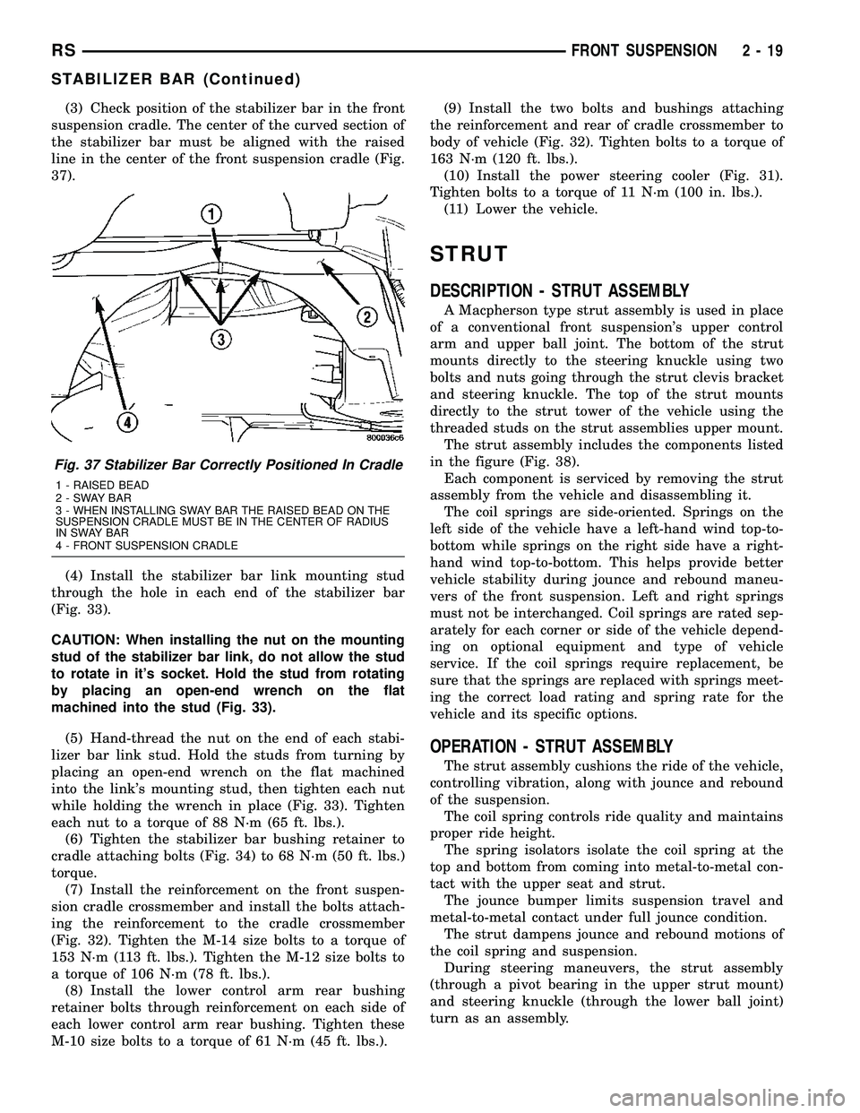
(3) Check position of the stabilizer bar in the front
suspension cradle. The center of the curved section of
the stabilizer bar must be aligned with the raised
line in the center of the front suspension cradle (Fig.
37).
(4) Install the stabilizer bar link mounting stud
through the hole in each end of the stabilizer bar
(Fig. 33).
CAUTION: When installing the nut on the mounting
stud of the stabilizer bar link, do not allow the stud
to rotate in it's socket. Hold the stud from rotating
by placing an open-end wrench on the flat
machined into the stud (Fig. 33).
(5) Hand-thread the nut on the end of each stabi-
lizer bar link stud. Hold the studs from turning by
placing an open-end wrench on the flat machined
into the link's mounting stud, then tighten each nut
while holding the wrench in place (Fig. 33). Tighten
each nut to a torque of 88 N´m (65 ft. lbs.).
(6) Tighten the stabilizer bar bushing retainer to
cradle attaching bolts (Fig. 34) to 68 N´m (50 ft. lbs.)
torque.
(7) Install the reinforcement on the front suspen-
sion cradle crossmember and install the bolts attach-
ing the reinforcement to the cradle crossmember
(Fig. 32). Tighten the M-14 size bolts to a torque of
153 N´m (113 ft. lbs.). Tighten the M-12 size bolts to
a torque of 106 N´m (78 ft. lbs.).
(8) Install the lower control arm rear bushing
retainer bolts through reinforcement on each side of
each lower control arm rear bushing. Tighten these
M-10 size bolts to a torque of 61 N´m (45 ft. lbs.).(9) Install the two bolts and bushings attaching
the reinforcement and rear of cradle crossmember to
body of vehicle (Fig. 32). Tighten bolts to a torque of
163 N´m (120 ft. lbs.).
(10) Install the power steering cooler (Fig. 31).
Tighten bolts to a torque of 11 N´m (100 in. lbs.).
(11) Lower the vehicle.
STRUT
DESCRIPTION - STRUT ASSEMBLY
A Macpherson type strut assembly is used in place
of a conventional front suspension's upper control
arm and upper ball joint. The bottom of the strut
mounts directly to the steering knuckle using two
bolts and nuts going through the strut clevis bracket
and steering knuckle. The top of the strut mounts
directly to the strut tower of the vehicle using the
threaded studs on the strut assemblies upper mount.
The strut assembly includes the components listed
in the figure (Fig. 38).
Each component is serviced by removing the strut
assembly from the vehicle and disassembling it.
The coil springs are side-oriented. Springs on the
left side of the vehicle have a left-hand wind top-to-
bottom while springs on the right side have a right-
hand wind top-to-bottom. This helps provide better
vehicle stability during jounce and rebound maneu-
vers of the front suspension. Left and right springs
must not be interchanged. Coil springs are rated sep-
arately for each corner or side of the vehicle depend-
ing on optional equipment and type of vehicle
service. If the coil springs require replacement, be
sure that the springs are replaced with springs meet-
ing the correct load rating and spring rate for the
vehicle and its specific options.
OPERATION - STRUT ASSEMBLY
The strut assembly cushions the ride of the vehicle,
controlling vibration, along with jounce and rebound
of the suspension.
The coil spring controls ride quality and maintains
proper ride height.
The spring isolators isolate the coil spring at the
top and bottom from coming into metal-to-metal con-
tact with the upper seat and strut.
The jounce bumper limits suspension travel and
metal-to-metal contact under full jounce condition.
The strut dampens jounce and rebound motions of
the coil spring and suspension.
During steering maneuvers, the strut assembly
(through a pivot bearing in the upper strut mount)
and steering knuckle (through the lower ball joint)
turn as an assembly.
Fig. 37 Stabilizer Bar Correctly Positioned In Cradle
1 - RAISED BEAD
2-SWAYBAR
3 - WHEN INSTALLING SWAY BAR THE RAISED BEAD ON THE
SUSPENSION CRADLE MUST BE IN THE CENTER OF RADIUS
IN SWAY BAR
4 - FRONT SUSPENSION CRADLE
RSFRONT SUSPENSION2-19
STABILIZER BAR (Continued)
Page 62 of 2339
(2) Remove the wheel and tire assembly from loca-
tion on front of vehicle requiring strut removal.
(3) If both strut assemblies are to be removed,
mark the strut assemblies right or left according to
which side of the vehicle they were removed from.
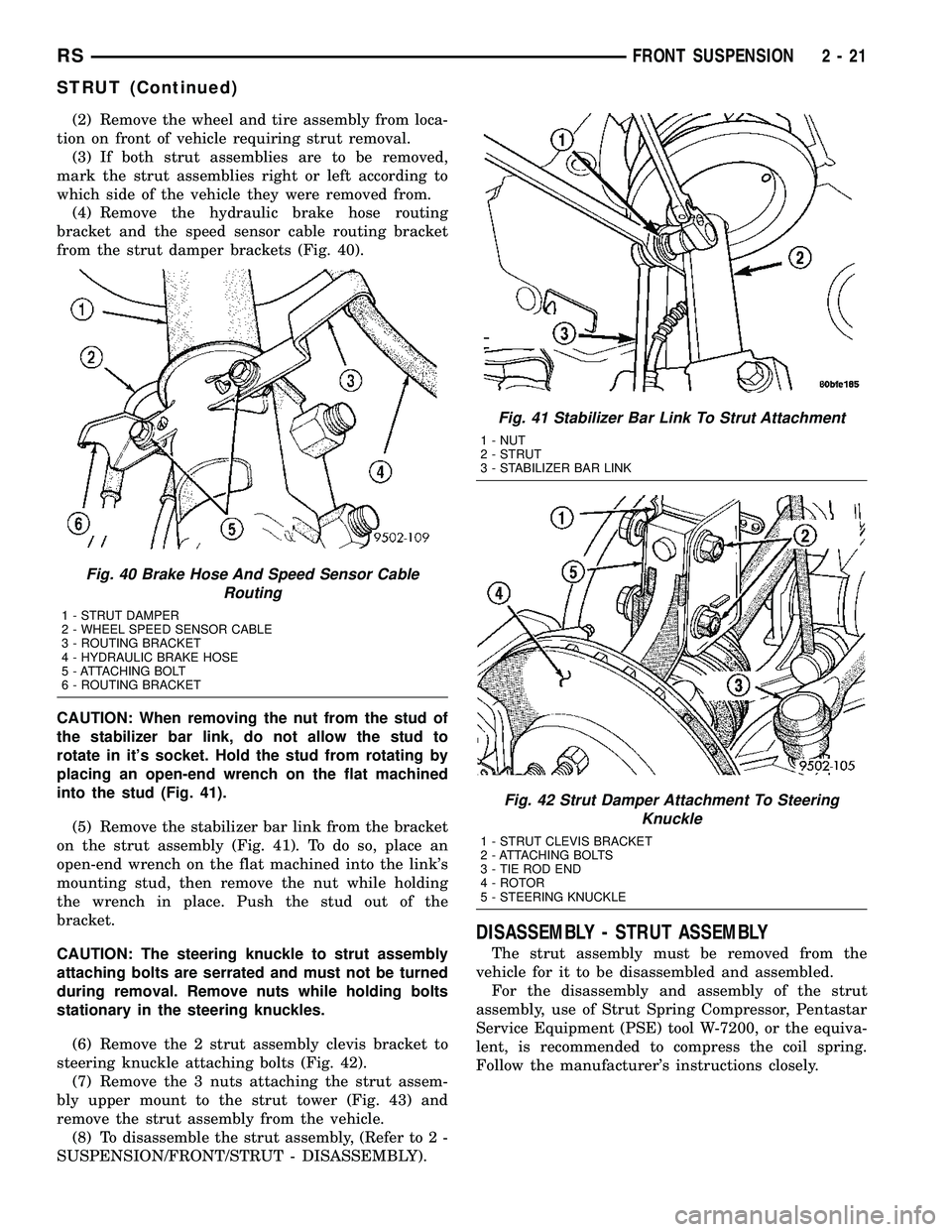
(4) Remove the hydraulic brake hose routing
bracket and the speed sensor cable routing bracket
from the strut damper brackets (Fig. 40).
CAUTION: When removing the nut from the stud of
the stabilizer bar link, do not allow the stud to
rotate in it's socket. Hold the stud from rotating by
placing an open-end wrench on the flat machined
into the stud (Fig. 41).
(5) Remove the stabilizer bar link from the bracket
on the strut assembly (Fig. 41). To do so, place an
open-end wrench on the flat machined into the link's
mounting stud, then remove the nut while holding
the wrench in place. Push the stud out of the
bracket.
CAUTION: The steering knuckle to strut assembly
attaching bolts are serrated and must not be turned
during removal. Remove nuts while holding bolts
stationary in the steering knuckles.
(6) Remove the 2 strut assembly clevis bracket to
steering knuckle attaching bolts (Fig. 42).
(7) Remove the 3 nuts attaching the strut assem-
bly upper mount to the strut tower (Fig. 43) and
remove the strut assembly from the vehicle.
(8) To disassemble the strut assembly, (Refer to 2 -
SUSPENSION/FRONT/STRUT - DISASSEMBLY).
DISASSEMBLY - STRUT ASSEMBLY
The strut assembly must be removed from the
vehicle for it to be disassembled and assembled.
For the disassembly and assembly of the strut
assembly, use of Strut Spring Compressor, Pentastar
Service Equipment (PSE) tool W-7200, or the equiva-
lent, is recommended to compress the coil spring.
Follow the manufacturer's instructions closely.
Fig. 40 Brake Hose And Speed Sensor Cable
Routing
1 - STRUT DAMPER
2 - WHEEL SPEED SENSOR CABLE
3 - ROUTING BRACKET
4 - HYDRAULIC BRAKE HOSE
5 - ATTACHING BOLT
6 - ROUTING BRACKET
Fig. 41 Stabilizer Bar Link To Strut Attachment
1 - NUT
2 - STRUT
3 - STABILIZER BAR LINK
Fig. 42 Strut Damper Attachment To Steering
Knuckle
1 - STRUT CLEVIS BRACKET
2 - ATTACHING BOLTS
3 - TIE ROD END
4 - ROTOR
5 - STEERING KNUCKLE
RSFRONT SUSPENSION2-21
STRUT (Continued)
Page 66 of 2339

(12) Slowly release the tension from the coil spring
by backing off the compressor drive fully. As the ten-
sion is relieved, make sure the upper mount, pivot
bearing and upper seat are align properly. Remove
the clamp from the lower end of the coil spring and
strut. Push back the spring compressor upper and
lower hooks, then remove the strut assembly from
the spring compressor.
(13) Install strut assembly on the vehicle. (Refer to
2 - SUSPENSION/FRONT/STRUT - INSTALLA-
TION)
INSTALLATION - STRUT ASSEMBLY
CAUTION: Front strut coil springs are side-oriented.
When installing a strut assembly, make sure the
strut being installed has the correct coil spring for
that side of the vehicle. Springs on the left side of
the vehicle have a left-hand wind top-to-bottom
while springs on the right side have a right-hand
wind top-to-bottom (Fig. 49). Do not interchange the
two sides.
(1) Install strut assembly into strut tower, aligning
and installing the 3 studs on the upper strut mount
into the holes in shock tower. Install the 3 upper
strut mount attaching nut/washer assemblies (Fig.
43). Then using a crow foot. tighten the 3 attaching
nuts to a torque of 28 N´m (250 in. lbs.).
CAUTION: The steering knuckle to strut assembly
attaching bolts are serrated and must not be turned
during installation. Install nuts while holding bolts
stationary in the steering knuckles.
NOTE: The strut clevis-to-steering knuckle bolts are
installed differently on each side of the vehicle. Left
hand side bolts are to be installed from vehicle rear
to front. Right side bolts are to be installed from
vehicle front to rear.(2) Align strut assembly with steering knuckle.
Position arm of steering knuckle into strut assembly
clevis bracket. Align the strut assembly clevis
bracket mounting holes with the steering knuckle
mounting holes. Install the 2 strut assembly to steer-
ing knuckle attaching bolts (Fig. 42).If strut assem-
bly is attached to steering knuckle using a cam
bolt, the cam bolt must be installed in the lower
slotted hole on strut clevis bracket.Tighten the
strut clevis-to-steering knuckle attaching bolts to a
torque of 81 N´m (60 ft. lbs.) plus an additional 1/4
(90É) turn after specified torque is met.
(3) Install the stabilizer bar link mounting stud
through the bracket on the strut assembly (Fig. 41).
CAUTION: When installing the nut on the mounting
stud of the stabilizer bar link, do not allow the stud
to rotate in it's socket. Hold the stud from rotating
by placing an open-end wrench on the flat
machined into the stud (Fig. 41).
(4) Hand thread the nut on the end of the stabi-
lizer bar link stud. Hold the stud from turning by
placing an open-end wrench on the flat machined
into the link's mounting stud, then tighten the nut
while holding the wrench in place (Fig. 41). Tighten
the nut to a torque of 88 N´m (65 ft. lbs.).
(5) Install the hydraulic brake hose and speed sen-
sor cable routing brackets on the strut assembly
brackets (Fig. 40). Tighten the routing bracket
attaching bolts to a torque of 13 N´m (10 ft. lbs.).
(6) Install the wheel/tire assembly on the vehicle.
(7) Install and tighten the wheel mounting stud
nuts in proper sequence until all nuts are torqued to
half specification. Then repeat the tightening
sequence to the full specified torque of 135 N´m (100
ft. lbs.).
RSFRONT SUSPENSION2-25
STRUT (Continued)
Page 186 of 2339

INSTALLATION - LEFT REAR
(1) Install the rear parking brake cable in the
brake support plate. Insert cable housing retainer
into brake support plate making certain that cable
housing retainer fingers lock the housing and
retainer firmly into place.
(2) Attach the parking brake cable onto the park
brake actuator lever.
(3) Install the brake shoes on the rear brake sup-
port plate. (Refer to 5 - BRAKES/HYDRAULIC/ME-
CHANICAL/BRAKE PADS/SHOES -
INSTALLATION).
(4) Insert cable housing retainer into body outrig-
ger bracket making certain that cable housing
retainer fingers lock the housing firmly into place.
(5) Connect rear parking brake cable to the equal-
izer bracket (Fig. 115).
(6) Install brake drum, and wheel and tire assem-
bly.
(7) Remove the locking pliers from the front park
brake cable. This will automatically adjust the park
brake cables.
(8) Apply and release park brake pedal 1 time.
This will seat the park brake cables.
INSTALLATION - FOLD-IN-FLOOR SEATING
(1) Pass the leading end of the rear parking brake
cable through the hole in the end of the intermediate
bracket (Fig. 123). Press the cable housing retainer
through the hole until the fingers on the retainer
lock it into place.
(2) Route the cable back toward the brake assem-
bly placing it in the routing clip fastened to the
underbody of the vehicle (Fig. 119). Make sure to
stay to the inside of the left stabilizer bar link while
routing either cable.
(3) If the right rear cable is being serviced, install
screws, attaching the cable routing clamps to the
rear axle (Fig. 120).
(4) Pass the cable through the hole in the brake
adapter and hook the cable eyelet to the shoe lever
(Fig. 121).
(5) Install the screw fastening the cable to the rear
brake adapter (Fig. 121).
(6) Pull straight back on the front cable button
(and pliers) and properly attach the equalizer to all
three parking brake cables (Fig. 118).
(7) Remove the locking pliers from the front park-
ing brake cable and allow the automatic self-adjust-
ing mechanism in the lever to take up any slack.
(8) Lower the vehicle.
(9) Apply and release park brake pedal 1 time.
This will seat the parking brake cables.
LEVER - PARKING BRAKE
REMOVAL
(1) Manually release the automatic self-adjusting
mechanism tension of the parking brake lever (pedal)
assembly. (Refer to 5 - BRAKES/PARKING BRAKE -
STANDARD PROCEDURE).
(2) Disconnect negative (ground) cable from the
battery and isolate cable from battery terminal.
(3) Remove sill scuff plate from left door sill.
(4) Remove the left side kick panel.
(5) Remove the steering column cover from the
lower instrument panel.
(6) Remove the reinforcement from the lower
instrument panel.
(7) Remove the three bolts mounting the wiring
junction block to the instrument panel.
NOTE: When removing the lower mounting bolt,
push the park brake pedal down 5 clicks to access
the lower mounting bolt.
(8) Remove the lower bolt mounting the parking
brake lever (pedal) to the body (Fig. 124).
(9) Remove the forward nut mounting the parking
brake lever to the body (Fig. 124).
(10) Remove the upper bolt mounting the parking
brake lever to the body (Fig. 124).
(11) Pull downward on front parking brake cable
while rotating lever assembly out from behind junc-
tion block.
(12) Remove the release link from the parking
brake lever assembly.
(13) Disconnect the wiring connector from the indi-
cator lamp ground switch (Fig. 124) (Fig. 125).
Fig. 124 Parking Brake Lever Mounting
1 - WIRE HARNESS CONNECTOR
2 - LEVER MECHANISM
3 - FRONT CABLE
RSBRAKES - BASE5-75
CABLE - PARKING BRAKE REAR (Continued)