ECO CHRYSLER PACIFICA 2017 2.G Repair Manual
[x] Cancel search | Manufacturer: CHRYSLER, Model Year: 2017, Model line: PACIFICA, Model: CHRYSLER PACIFICA 2017 2.GPages: 828, PDF Size: 7.58 MB
Page 190 of 828
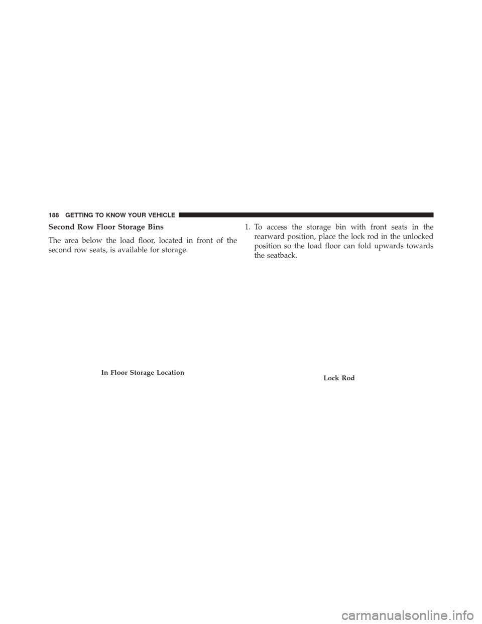
Second Row Floor Storage Bins
The area below the load floor, located in front of the
second row seats, is available for storage.1. To access the storage bin with front seats in the
rearward position, place the lock rod in the unlocked
position so the load floor can fold upwards towards
the seatback.
In Floor Storage LocationLock Rod
188 GETTING TO KNOW YOUR VEHICLE
Page 191 of 828
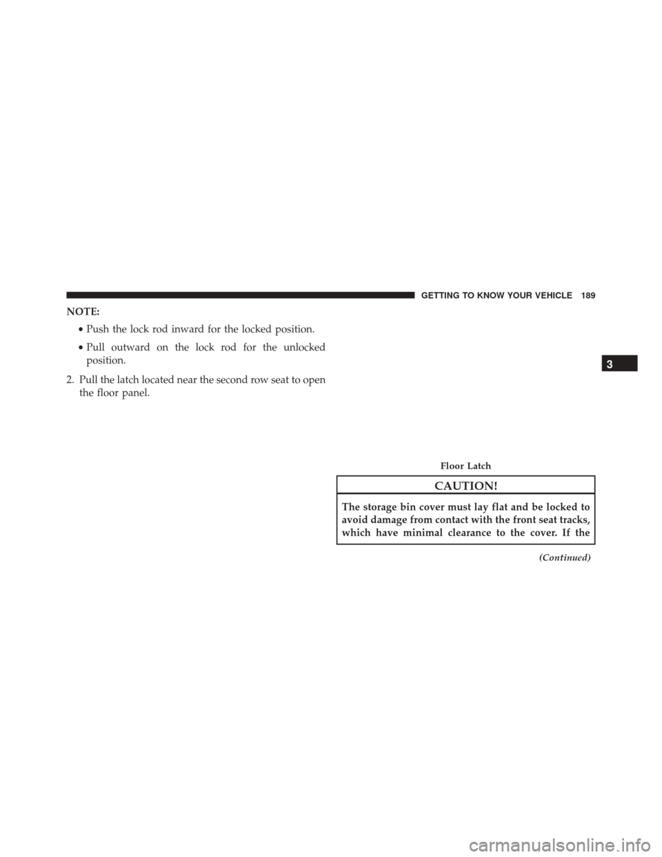
NOTE:•Push the lock rod inward for the locked position.
• Pull outward on the lock rod for the unlocked
position.
2. Pull the latch located near the second row seat to open the floor panel.
CAUTION!
The storage bin cover must lay flat and be locked to
avoid damage from contact with the front seat tracks,
which have minimal clearance to the cover. If the
(Continued)
Floor Latch
3
GETTING TO KNOW YOUR VEHICLE 189
Page 192 of 828
CAUTION!(Continued)
storage bin cover is left in the open position, front
seat adjustment may damage the cover.
WARNING!
In a collision, serious injury could result if the seat
storage bin covers are not properly latched.
•Do not drive the vehicle with the storage bin covers
open.
• Keep the storage bin covers closed and latched
while the vehicle is in motion.
• Do not operate the storage bin covers while the
vehicle is in motion.
• Do not use a storage bin latch as a tie down.
Storage Bin Safety Warning
Carefully follow these warnings to help prevent personal
injury or damage to your vehicle:
WARNING!
•Always close the storage bin covers when your
vehicle is unattended.
• Do not allow children to have access to the second
row seat storage bins. Once in the storage bin,
young children may not be able to escape. If
trapped in the storage bin, children can die from
suffocation or heat stroke.
• In a collision, serious injury could result if the seat
storage bin covers are not properly latched.
• Do not drive the vehicle with the storage bin covers
open. Keep the storage bin covers closed and
latched while the vehicle is in motion.
(Continued)
190 GETTING TO KNOW YOUR VEHICLE
Page 194 of 828
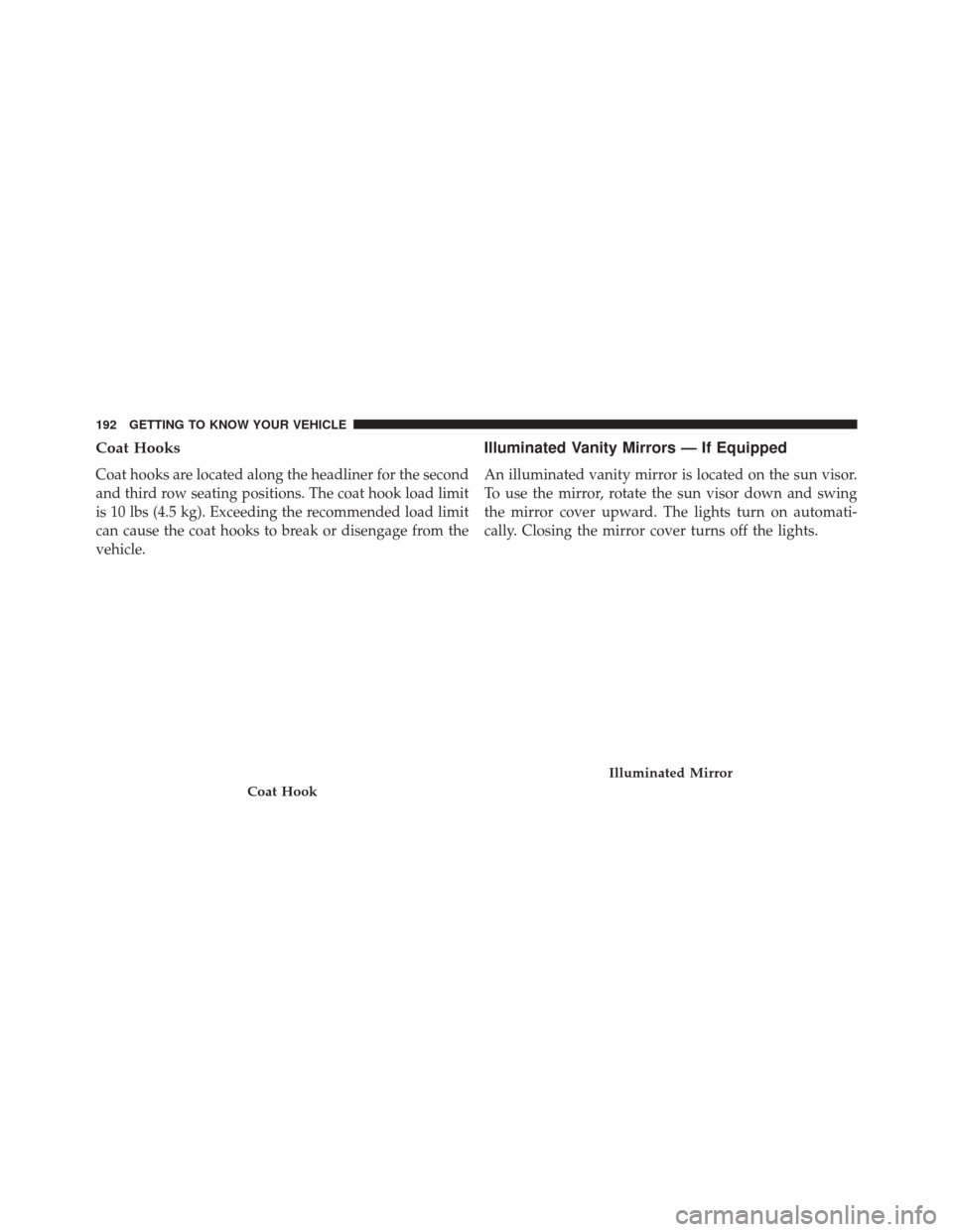
Coat Hooks
Coat hooks are located along the headliner for the second
and third row seating positions. The coat hook load limit
is 10 lbs (4.5 kg). Exceeding the recommended load limit
can cause the coat hooks to break or disengage from the
vehicle.
Illuminated Vanity Mirrors — If Equipped
An illuminated vanity mirror is located on the sun visor.
To use the mirror, rotate the sun visor down and swing
the mirror cover upward. The lights turn on automati-
cally. Closing the mirror cover turns off the lights.
Coat Hook
Illuminated Mirror
192 GETTING TO KNOW YOUR VEHICLE
Page 195 of 828
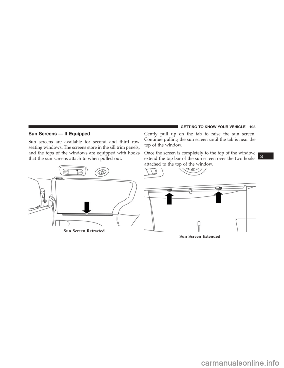
Sun Screens — If Equipped
Sun screens are available for second and third row
seating windows. The screens store in the sill trim panels,
and the tops of the windows are equipped with hooks
that the sun screens attach to when pulled out.Gently pull up on the tab to raise the sun screen.
Continue pulling the sun screen until the tab is near the
top of the window.
Once the screen is completely to the top of the window,
extend the top bar of the sun screen over the two hooks
attached to the top of the window.
Sun Screen Retracted
Sun Screen Extended
3
GETTING TO KNOW YOUR VEHICLE 193
Page 201 of 828
Cigar Lighter — If Equipped
NOTE:Cigar lighters can be purchased at an authorized
dealer through MOPAR parts. To ensure proper cigar
lighter operation, a MOPAR knob and element must be
used.
The cigar lighter is located at the bottom of the instru-
ment panel. Push lighter inward to heat.
After a few seconds, the lighter automatically returns to
its initial position and is ready to be used.
WARNING!
When the cigar lighter is in use it becomes very hot.
To avoid serious injury, handle the cigar lighter with
care. Always check that the cigar lighter has turned
off.
CAUTION!
Do not connect devices with power higher than 180
Watts (15 Amps) to the socket. Do not damage the
socket by using unsuitable adaptors. If the 180 Watt
(15 Amp) power rating is exceeded the fuse protect-
ing the system will need to be replaced.
Smoker’s Package Kit — If Equipped
With the optional authorized dealer-installed Smoker’s
Package Kit, a removable ash receiver is inserted into one
of the two cupholders in the center floor console. To
install the ash receiver, align the receiver so the thumb
grip on the lid is facing rearward. Push the ash receiver
into either of the cup wells to secure. Pull upward on the
ash receiver to remove for cleaning and/or storage.
The left rear trim panel cupholder is designed to accom-
modate a second ash receiver, if desired.
3
GETTING TO KNOW YOUR VEHICLE 199
Page 206 of 828
Once the crossbar is in place, tighten both thumb screws
completely.Deploy and tighten the second crossbar to complete the
deployment of the crossbars.
NOTE:
The crossbars are not identical and have fixed
deployment positions. Rear crossbar can deployed in two
different positions.
Positioning CrossbarsInstalling Crossbars
204 GETTING TO KNOW YOUR VEHICLE
Page 209 of 828
Once the driver ’s side crossbar is in place, tighten the
thumb screws completely.Repeat the procedure to stow the second crossbar on the
opposite side.
Tightening CrossbarStowed Crossbars
3
GETTING TO KNOW YOUR VEHICLE 207
Page 218 of 828
•Fuel Economy Info
• Trip (Trip A/Trip B)
• Audio
• Navigation
• Messages
• Screen Setup
• Speed Warning — 7” DID
The system allows the driver to select information by
pushing the following buttons mounted on the steering
wheel: •UP Arrow Button
Push and release the UParrow button to scroll
upward through the Main Menu items.
Instrument Cluster Display (EVIC/DID) Control Buttons
216 GETTING TO KNOW YOUR INSTRUMENT PANEL
Page 219 of 828
•DOWN Arrow Button
Push and release the DOWNarrow button to
scroll downward through the Main Menu
items.
• RIGHT Arrow Button
Push and release the RIGHTarrow button to
access the information screens or submenu
screens of a main menu item.
• BACK/LEFT Arrow Button
Push and release the LEFTarrow button to
access the information screens or submenu
screens of a main menu item.
• OK Button
Push the OKbutton to access/select the information
screens or submenu screens of a Main Menu item. Push and hold the
OKarrow button for one second to reset
displayed/selected features that can be reset.
Oil Change Reset
• Your vehicle is equipped with an engine oil change
indicator system. The “Oil Change Due” message will
flash in the instrument cluster display for approxi-
mately 10 seconds after a single chime has sounded, to
indicate the next scheduled oil change interval. The
engine oil change indicator system is duty cycle based,
which means the engine oil change interval may
fluctuate, dependent upon your personal driving style.
• Unless reset, this message will continue to display
each time the ignition is cycled to the ON/RUN
position. To reset the oil change indicator system (after
performing the scheduled maintenance) refer to the
following procedure.
4
GETTING TO KNOW YOUR INSTRUMENT PANEL 217