mount CHRYSLER PACIFICA 2018 Owner's Guide
[x] Cancel search | Manufacturer: CHRYSLER, Model Year: 2018, Model line: PACIFICA, Model: CHRYSLER PACIFICA 2018Pages: 696, PDF Size: 8.48 MB
Page 423 of 696
WARNING!(Continued)
•Driving through standing water limits your vehicle’s
braking capabilities, which increases stopping dis-
tances. Therefore, after driving through standing
water, drive slowly and lightly press on the brake
pedal several times to dry the brakes.
• Failure to follow these warnings may result in inju-
ries that are serious or fatal to you, your passengers,
and others around you.
CAUTION!
•Always check the depth of the standing water before
driving through it. Never drive through standing
water that is deeper than the bottom of the tire rims
mounted on the vehicle.
• Determine the condition of the road or the path that
is under water and if there are any obstacles in the
way before driving through the standing water.
• Do not exceed 5 mph (8 km/h) when driving through
standing water. This will minimize wave effects.
(Continued)
CAUTION! (Continued)
•Driving through standing water may cause damage
to your vehicle’s drivetrain components. Always in-
spect your vehicle’s fluids (i.e., engine oil, transmis-
sion, axle, etc.) for signs of contamination (i.e., fluid
that is milky or foamy in appearance) after driving
through standing water. Do not continue to operate
the vehicle if any fluid appears contaminated, as this
may result in further damage. Such damage is not
covered by the New Vehicle Limited Warranty.
• Getting water inside your vehicle’s engine can cause
it to lock up and stall out, and cause serious internal
damage to the engine. Such damage is not covered by
the New Vehicle Limited Warranty.
6
STARTING AND OPERATING 421
Page 434 of 696
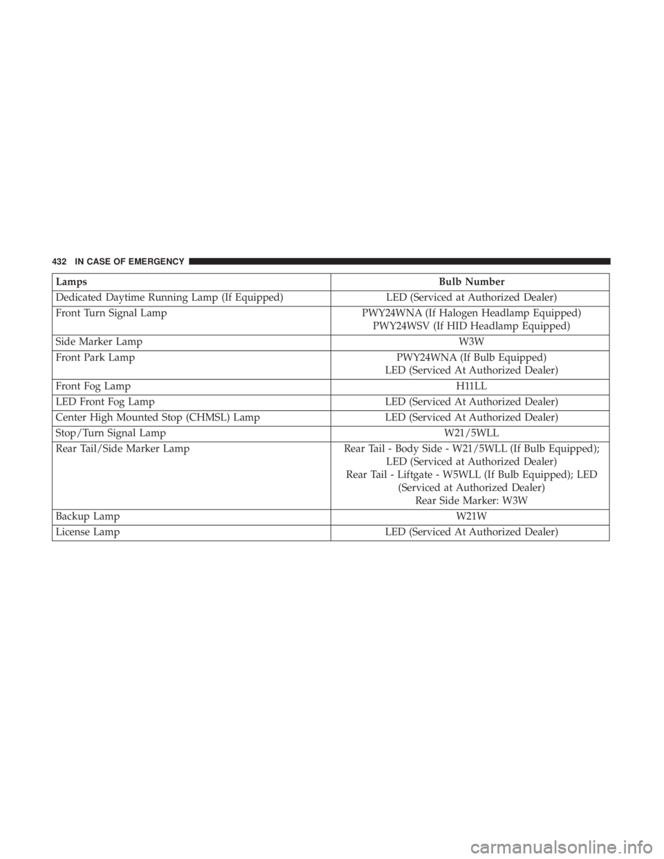
LampsBulb Number
Dedicated Daytime Running Lamp (If Equipped) LED (Serviced at Authorized Dealer)
Front Turn Signal Lamp PWY24WNA (If Halogen Headlamp Equipped)
PWY24WSV (If HID Headlamp Equipped)
Side Marker Lamp W3W
Front Park Lamp PWY24WNA (If Bulb Equipped)
LED (Serviced At Authorized Dealer)
Front Fog Lamp H11LL
LED Front Fog Lamp LED (Serviced At Authorized Dealer)
Center High Mounted Stop (CHMSL) Lamp LED (Serviced At Authorized Dealer)
Stop/Turn Signal Lamp W21/5WLL
Rear Tail/Side Marker Lamp Rear Tail - Body Side - W21/5WLL (If Bulb Equipped);
LED (Serviced at Authorized Dealer)
Rear Tail - Liftgate - W5WLL (If Bulb Equipped); LED (Serviced at Authorized Dealer)Rear Side Marker: W3W
Backup Lamp W21W
License Lamp LED (Serviced At Authorized Dealer)
432 IN CASE OF EMERGENCY
Page 439 of 696
CAUTION!
Do not touch the new bulb with your fingers. Oil
contamination will severely shorten bulb life. If the
bulb comes in contact with any oily surface, clean the
bulb with rubbing alcohol.
5. Install the front fog lamp bulb into the front fog lamp housing, and rotate the bulb clockwise to lock it in place.
6. Position the inner wheel liner in place and install fasteners.
Rear Liftgate Mounted Back-Up Lamps And Tail
Lamps (If Bulb Equipped)
1. Raise the liftgate.
2. Use a fiber stick or flat blade screw driver to pry off thebulb access cover on the lower liftgate trim.
3. Back-up lamps/tail lamp (if bulb equipped) are now visible. Rotate socket(s) counter clockwise.
4. Remove/replace bulb(s).
5. Reinstall the socket(s)
6. Reverse process to reinstall the liftgate trim.
Rear Bodyside Mounted Taillamps
1. Raise the liftgate.
2. Remove two torx head screws on bodyside lamp using a T30 screwdriver.
3. Remove lamp from vehicle body and locate bulb socket on rear of lamp. Rotate socket counter-clockwise.
4. Remove/replace bulb(s).
5. Reinstall the socket(s)
6. Reverse process to reinstall the lamp onto vehicle.
Center High-Mounted Stop Lamp (CHMSL)
The center high-mounted stop lamp is an LED assembly.
See your authorized dealer for replacement.
Rear License Lamp
The rear license lamps are LED. See your authorized dealer
for replacement.
7
IN CASE OF EMERGENCY 437
Page 455 of 696
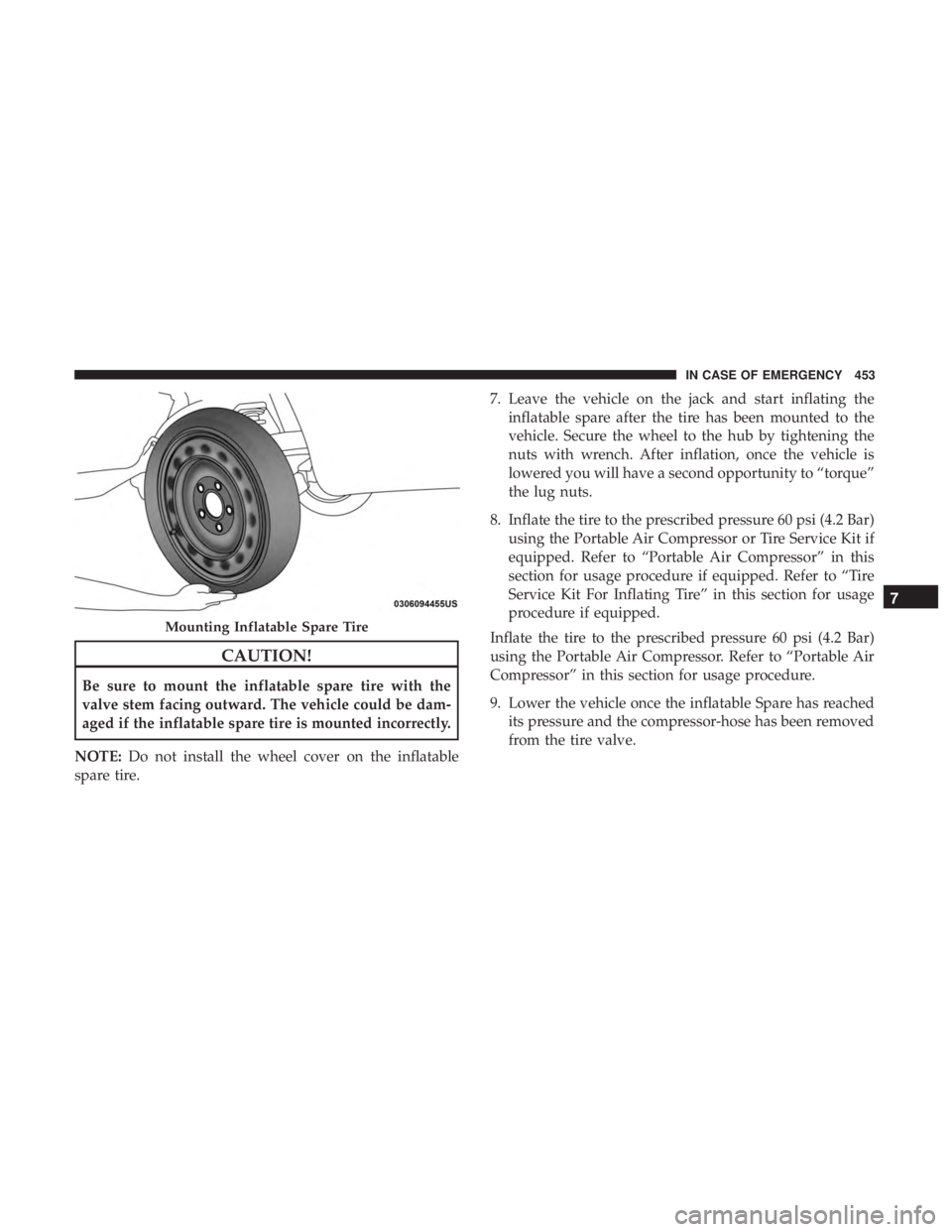
CAUTION!
Be sure to mount the inflatable spare tire with the
valve stem facing outward. The vehicle could be dam-
aged if the inflatable spare tire is mounted incorrectly.
NOTE: Do not install the wheel cover on the inflatable
spare tire. 7. Leave the vehicle on the jack and start inflating the
inflatable spare after the tire has been mounted to the
vehicle. Secure the wheel to the hub by tightening the
nuts with wrench. After inflation, once the vehicle is
lowered you will have a second opportunity to “torque”
the lug nuts.
8. Inflate the tire to the prescribed pressure 60 psi (4.2 Bar) using the Portable Air Compressor or Tire Service Kit if
equipped. Refer to “Portable Air Compressor” in this
section for usage procedure if equipped. Refer to “Tire
Service Kit For Inflating Tire” in this section for usage
procedure if equipped.
Inflate the tire to the prescribed pressure 60 psi (4.2 Bar)
using the Portable Air Compressor. Refer to “Portable Air
Compressor” in this section for usage procedure.
9. Lower the vehicle once the inflatable Spare has reached its pressure and the compressor-hose has been removed
from the tire valve.
Mounting Inflatable Spare Tire
7
IN CASE OF EMERGENCY 453
Page 457 of 696
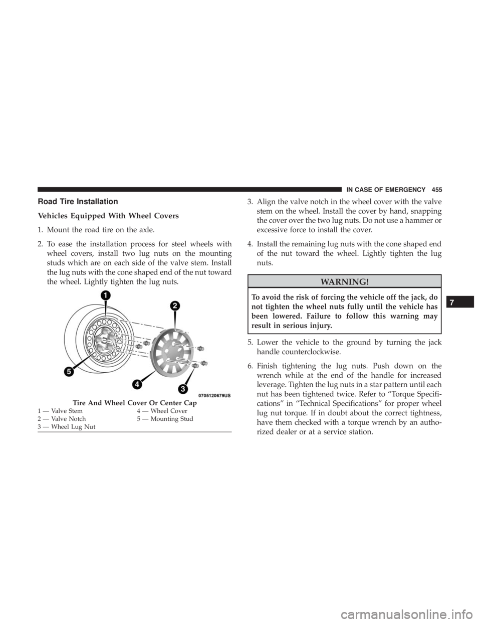
Road Tire Installation
Vehicles Equipped With Wheel Covers
1. Mount the road tire on the axle.
2. To ease the installation process for steel wheels withwheel covers, install two lug nuts on the mounting
studs which are on each side of the valve stem. Install
the lug nuts with the cone shaped end of the nut toward
the wheel. Lightly tighten the lug nuts. 3. Align the valve notch in the wheel cover with the valve
stem on the wheel. Install the cover by hand, snapping
the cover over the two lug nuts. Do not use a hammer or
excessive force to install the cover.
4. Install the remaining lug nuts with the cone shaped end of the nut toward the wheel. Lightly tighten the lug
nuts.
WARNING!
To avoid the risk of forcing the vehicle off the jack, do
not tighten the wheel nuts fully until the vehicle has
been lowered. Failure to follow this warning may
result in serious injury.
5. Lower the vehicle to the ground by turning the jack handle counterclockwise.
6. Finish tightening the lug nuts. Push down on the wrench while at the end of the handle for increased
leverage. Tighten the lug nuts in a star pattern until each
nut has been tightened twice. Refer to “Torque Specifi-
cations” in “Technical Specifications” for proper wheel
lug nut torque. If in doubt about the correct tightness,
have them checked with a torque wrench by an autho-
rized dealer or at a service station.
Tire And Wheel Cover Or Center Cap1 — Valve Stem 4 — Wheel Cover
2 — Valve Notch 5 — Mounting Stud
3 — Wheel Lug Nut
7
IN CASE OF EMERGENCY 455
Page 458 of 696
7. After 25 miles (40 km) check the lug nut torque with atorque wrench to ensure that all lug nuts are properly
seated against the wheel.
Vehicles Without Wheel Covers
1. Mount the road tire on the axle.
2. Install the remaining lug nuts with the cone shaped endof the nut toward the wheel. Lightly tighten the lug
nuts.
WARNING!
To avoid the risk of forcing the vehicle off the jack, do
not tighten the wheel nuts fully until the vehicle has
been lowered. Failure to follow this warning may
result in serious injury. 3. Lower the vehicle to the ground by turning the jack
handle counterclockwise.
4. Finish tightening the lug nuts. Push down on the wrench while at the end of the handle for increased
leverage. Tighten the lug nuts in a star pattern until each
nut has been tightened twice. Refer to “Torque Specifi-
cations” in the “Technical Specifications” section for
proper wheel lug nut torque. If in doubt about the
correct tightness, have them checked with a torque
wrench by your authorized dealer or at a service station.
5. After 25 miles (40 km) check the lug nut torque with a torque wrench to ensure that all lug nuts are properly
seated against the wheel.
456 IN CASE OF EMERGENCY
Page 483 of 696
3. Using a small screwdriver or similar tool, remove theManual Park Release access cover, which is to the lower
left of the steering column.
4. The Manual Park Release access cover is connected to a red tether strap. Pull the tether strap out as far as it will
go, then release it. The transmission should now be in
NEUTRAL, allowing the vehicle to be moved.
NOTE: When the lever is locked in the released position,
the tether will remain outside of the trim panel and the
access cover cannot be re-installed.
5. Release the parking brake only when the vehicle is securely connected to a tow vehicle.
To Reset The Manual Park Release:
1. Apply firm pressure to the brake pedal while seated in the driver ’s seat.
2. Pull the tether strap out again, then release it.
3. Allow the tether to retract with the lever back to its original position. 4. Verify that the transmission is in PARK.
5. Confirm that the tether has retracted fully and re-install
the access cover. If the access cover cannot be re-
installed, repeat steps 1 through 4.
FREEING A STUCK VEHICLE
If your vehicle becomes stuck in mud, sand or snow, it can
often be moved using a rocking motion. Turn the steering
wheel right and left to clear the area around the front
wheels. Then shift back and forth between DRIVE and
REVERSE while gently pressing the accelerator.
NOTE: Shifts between DRIVE and REVERSE can only be
achieved at wheel speeds of 5 mph (8 km/h) or less.
Whenever the transmission remains in NEUTRAL for more
than two seconds, you must press the brake pedal to
engage DRIVE or REVERSE.
Use the least amount of accelerator pedal pressure that will
maintain the rocking motion without spinning the wheels
or racing the engine.
7
IN CASE OF EMERGENCY 481
Page 497 of 696
When refilling the washer fluid reservoir, take some
washer fluid, apply it to a cloth or towel, and wipe clean
the wiper blades; this will help blade performance.
To prevent freeze-up of your windshield washer system in
cold weather, select a solution or mixture that meets or
exceeds the temperature range of your climate. This rating
information can be found on most washer fluid containers.
WARNING!
Commercially available windshield washer solvents
are flammable. They could ignite and burn you. Care
must be exercised when filling or working around the
washer solution.
Maintenance-Free Battery
Your vehicle is equipped with a maintenance-free battery.
You will never have to add water, nor is periodic mainte-
nance required.
WARNING!
•Battery fluid is a corrosive acid solution and can
burn or even blind you. Do not allow battery fluid to
(Continued)
WARNING! (Continued)
contact your eyes, skin, or clothing. Do not lean over
a battery when attaching clamps. If acid splashes in
eyes or on skin, flush the area immediately with
large amounts of water. Refer to “Jump Starting
Procedure” in “In Case Of Emergency” for further
information.
• Battery gas is flammable and explosive. Keep flame
or sparks away from the battery. Do not use a booster
battery or any other booster source with an output
greater than 12 Volts. Do not allow cable clamps to
touch each other.
• Battery posts, terminals, and related accessories con-
tain lead and lead compounds. Wash hands after
handling.
CAUTION!
•It is essential when replacing the cables on the
battery that the positive cable is attached to the
positive post and the negative cable is attached to the
negative post. Battery posts are marked positive (+)
and negative (-) and are identified on the battery
(Continued)
8
SERVICING AND MAINTENANCE 495
Page 505 of 696
7. Remove the filter cover by prying back each of theretaining tabs from their hooking points, and then
pulling out the filter cover to expose the cabin air filter.
Remove the air filter by pulling it straight out of the
housing.
8. Install the new air filter with the arrow on the filter pointing toward the floor.
CAUTION!
The cabin air filter is identified with an arrow to
indicate airflow direction through the filter. Failure to
properly install the filter will result in the need to
replace it more often.
9. Once the filter is replaced, reinstall the filter cover, making sure the retaining tabs are fully secured into
their housings.
10. Close the cabin air filter compartment cover, and reinsert the snaps into their slots. Push the snap lids
until fully attached. 11. Push the glove compartment door to the near closed
position to reengage the glove compartment travel
stops. Finally, pull the glove compartment tension
tether clip down and slide it back into the slot on the
side of the glove compartment door.
Body Lubrication
Locks and all body pivot points, including such items as
seat tracks, door hinge pivot points and rollers, liftgate,
tailgate, decklid, sliding doors and hood hinges, should be
lubricated periodically with a lithium based grease, such as
Mopar Spray White Lube to assure quiet, easy operation
and to protect against rust and wear. Prior to the applica-
tion of any lubricant, the parts concerned should be wiped
clean to remove dust and grit; after lubricating excess oil
and grease should be removed. Particular attention should
also be given to hood latching components to ensure
proper function. When performing other underhood ser-
vices, the hood latch, release mechanism and safety catch
should be cleaned and lubricated.
The external lock cylinders should be lubricated twice a
year, preferably in the Fall and Spring. Apply a small
amount of a high quality lubricant, such as Mopar Lock
Cylinder Lubricant directly into the lock cylinder.
8
SERVICING AND MAINTENANCE 503
Page 514 of 696
Adding Coolant
Your vehicle has been built with an improved engine
coolant (OAT coolant conforming to MS.90032) that allows
extended maintenance intervals. This engine coolant (anti-
freeze) can be used up to ten years or 150,000 miles
(240,000 km) before replacement. To prevent reducing this
extended maintenance period, it is important that you use
the same engine coolant (OAT coolant conforming to
MS.90032) throughout the life of your vehicle.
Please review these recommendations for using Organic
Additive Technology (OAT) engine coolant (antifreeze)
that meets the requirements of FCA Material Standard
MS.90032. When adding engine coolant (antifreeze):
•We recommend using Mopar Antifreeze/Coolant 10
Year/150,000 Mile (240,000 km) Formula OAT (Organic
Additive Technology) that meets the requirements of
FCA Material Standard MS.90032.
• Mix a minimum solution of 50% OAT engine coolant
that meets the requirements of FCA Material Standard
MS.90032 and distilled water. Use higher concentrations
(not to exceed 70%) if temperatures below 34°F (37°C)
are anticipated. Please contact an authorized dealer for
assistance. •
Use only high purity water such as distilled or deionized
water when mixing the water/engine coolant (anti-
freeze) solution. The use of lower quality water will
reduce the amount of corrosion protection in the engine
cooling system.
NOTE:
• It is the owner’s responsibility to maintain the proper
level of protection against freezing according to the
temperatures occurring in the area where the vehicle is
operated.
• Some vehicles require special tools to add coolant prop-
erly. Failure to fill these systems properly could lead to
severe internal engine damage. If any coolant is needed
to be added to the system, please contact a local autho-
rized dealer.
• Mixing engine coolant (antifreeze) types is not recom-
mended and can result in cooling system damage. If
HOAT and OAT coolant are mixed in an emergency,
have a authorized dealer drain, flush, and refill with
OAT coolant (conforming to MS.90032) as soon as pos-
sible.
512 SERVICING AND MAINTENANCE