Jack CHRYSLER PACIFICA 2020 Owners Manual
[x] Cancel search | Manufacturer: CHRYSLER, Model Year: 2020, Model line: PACIFICA, Model: CHRYSLER PACIFICA 2020Pages: 516, PDF Size: 28.69 MB
Page 8 of 516
6
IN CASE OF EMERGENCY
HAZARD WARNING FLASHERS ....................... 301
ASSIST AND SOS MIRROR — IF EQUIPPED.... 301
General Information ..................................305
BULB REPLACEMENT ....................................... 306
Replacement Bulbs ...................................306
Replacing Exterior Bulbs ...........................308
FUSES .................................................................. 311
General Information ..................................311Fuse Location.............................................312Underhood Fuses.......................................312
JACKING AND TIRE CHANGING —
IF EQUIPPED ....................................................... 320
Jack And Spare Tire Location....................320
Equipment Removal .................................320
Preparations For Jacking ..........................321
Jacking Instructions ..................................322Road Tire Installation ................................325Portable Air Compressor — If Equipped....327
Tire Service Kit For Inflating Tire —
If Equipped .................................................328 Return Inflatable Spare Tire ......................330
TIRE SERVICE KIT — IF EQUIPPED ................... 330
JUMP STARTING................................................. 337
Preparations For Jump Start .....................337Jump Starting Procedure...........................338
REFUELING IN EMERGENCY ............................ 339
IF YOUR ENGINE OVERHEATS .......................... 339 MANUAL PARK RELEASE ................................. 340
FREEING A STUCK VEHICLE .............................341
TOWING A DISABLED VEHICLE .......................342
ENHANCED ACCIDENT RESPONSE SYSTEM
(EARS) .................................................................344
EVENT DATA RECORDER (EDR) .......................344
SERVICING AND MAINTENANCE
SCHEDULED SERVICING .................................. 345
Maintenance Plan ..................................... 345
ENGINE COMPARTMENT ................................... 349
3.6L Engine ................................................ 349
Checking Oil Level ..................................... 350
Adding Washer Fluid ................................. 350
Maintenance-Free Battery ....................... 350
Pressure Washing...................................... 351
DEALER SERVICE ..............................................351
Engine Oil .................................................. 351
Engine Oil Filter .......................................... 352Engine Air Cleaner ..................................... 353
Accessory Drive Belt Inspection ............... 353
Air Conditioner Maintenance .................... 354
Body Lubrication ........................................ 356
Windshield Wiper Blades .......................... 356Exhaust System ........................................ 359
Cooling System .......................................... 361Brake System ............................................ 364Automatic Transmission ........................... 365 RAISING THE VEHICLE ...................................... 366
TIRES .................................................................. 366
Tire Safety Information.............................. 366
Tires — General Information .................... 374Tire Types ................................................... 378
Spare Tires — If Equipped ......................... 379
Wheel And Wheel Trim Care ..................... 381
Tire Chains (Traction Devices) ................. 382
Tire Rotation Recommendations.............. 382
DEPARTMENT OF TRANSPORTATION UNIFORM
TIRE QUALITY GRADES .................................... 383
Treadwear .................................................. 383
Traction Grades ......................................... 383Temperature Grades ................................. 384
STORING THE VEHICLE ..................................... 384
BODYWORK ........................................................ 385
Protection From Atmospheric Agents....... 385
Body And Underbody Maintenance .......... 385Preserving The Bodywork.......................... 385
INTERIORS ......................................................... 386
Seats And Fabric Parts .............................. 386
Plastic And Coated Parts........................... 387
Leather Parts ............................................. 387
Glass Surfaces .......................................... 387
20_RU_OM_EN_US_t.book Page 6
Page 34 of 516
32GETTING TO KNOW YOUR VEHICLE
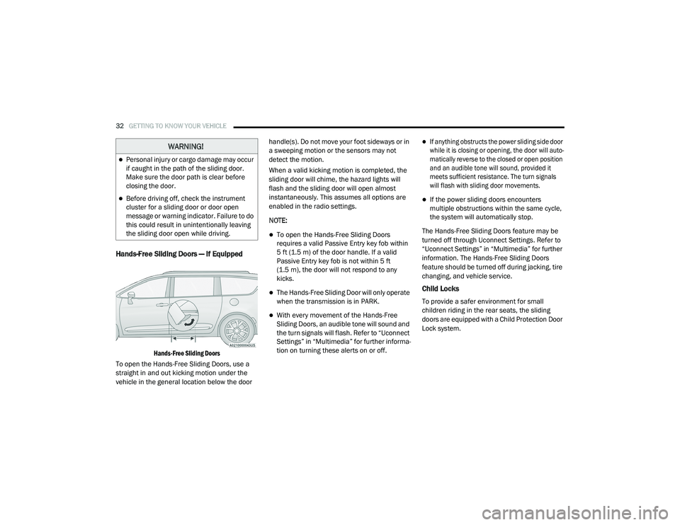
Hands-Free Sliding Doors — If Equipped
Hands-Free Sliding Doors
To open the Hands-Free Sliding Doors, use a
straight in and out kicking motion under the
vehicle in the general location below the door handle(s). Do not move your foot sideways or in
a sweeping motion or the sensors may not
detect the motion.
When a valid kicking motion is completed, the
sliding door will chime, the hazard lights will
flash and the sliding door will open almost
instantaneously. This assumes all options are
enabled in the radio settings.
NOTE:
To open the Hands-Free Sliding Doors
requires a valid Passive Entry key fob within
5 ft (1.5 m) of the door handle. If a valid
Passive Entry key fob is not within 5 ft
(1.5 m), the door will not respond to any
kicks.
The Hands-Free Sliding Door will only operate
when the transmission is in PARK.
With every movement of the Hands-Free
Sliding Doors, an audible tone will sound and
the turn signals will flash. Refer to “Uconnect
Settings” in “Multimedia” for further informa
-
tion on turning these alerts on or off.
If anything obstructs the power sliding side door
while it is closing or opening, the door will auto -
matically reverse to the closed or open position
and an audible tone will sound, provided it
meets sufficient resistance. The turn signals
will flash with sliding door movements.
If the power sliding doors encounters
multiple obstructions within the same cycle,
the system will automatically stop.
The Hands-Free Sliding Doors feature may be
turned off through Uconnect Settings. Refer to
“Uconnect Settings” in “Multimedia” for further
information. The Hands-Free Sliding Doors
feature should be turned off during jacking, tire
changing, and vehicle service.
Child Locks
To provide a safer environment for small
children riding in the rear seats, the sliding
doors are equipped with a Child Protection Door
Lock system.
WARNING!
Personal injury or cargo damage may occur
if caught in the path of the sliding door.
Make sure the door path is clear before
closing the door.
Before driving off, check the instrument
cluster for a sliding door or door open
message or warning indicator. Failure to do
this could result in unintentionally leaving
the sliding door open while driving.
20_RU_OM_EN_US_t.book Page 32
Page 104 of 516
102GETTING TO KNOW YOUR VEHICLE
(Continued)
NOTE:
To open the Hands-Free Liftgate requires a valid
Passive Entry key fob within 5 ft (1.5 m) of the
door handle. If a valid Passive Entry key fob is
not within 5 ft (1.5 m), the liftgate will not
respond to any kicks.
NOTE:
The Hands-Free Liftgate will only operate
when the transmission is in PARK.
If anything obstructs the Hands-Free Liftgate
while it is opening or closing, the liftgate will
automatically reverse to the closed position,
provided it meets sufficient resistance.
There are pinch sensors attached to the side
of the liftgate opening. Light pressure
anywhere along these strips will cause the
liftgate to return to the open position.
If the power liftgate encounters multiple
obstructions within the same cycle, the
system will automatically stop. If this occurs,
the liftgate must be operated manually.
The power liftgate will release, but not power
open, in temperatures below −12°F
(−24°C). Be sure to remove any buildup of
snow or ice from the liftgate before opening
the liftgate.
If the liftgate is left open for an extended
period of time, the liftgate may need to be
closed manually to reset power liftgate func-
tionality. Gas props support the liftgate in the open
position. However, because the gas pressure
drops with temperature, it may be necessary to
assist the props when opening the liftgate in
cold weather.
NOTE:
Allow the power system to open the liftgate.
Manually pushing or pulling the liftgate may
activate the liftgate obstacle detection feature
and stop the power operation or reverse its
direction.
CAUTION!
The Hands-Free Liftgate feature may be
turned on or off in Uconnect Settings. Refer to
“Uconnect Settings” in “Multimedia” for
further information. The Hands-Free Liftgate
feature should be turned off during Jacking,
Tire Changing, and Vehicle Service.
WARNING!
Driving with the liftgate open can allow
poisonous exhaust gases into your vehicle.
You and your passengers could be injured
by these fumes. Keep the liftgate closed
when you are operating the vehicle.
If you are required to drive with the liftgate
open, make sure that all windows are
closed, and the climate control blower
switch is set at high speed. Do not use the
recirculation mode.
WARNING!
During power operation, personal injury or
cargo damage may occur. Ensure the liftgate
travel path is clear. Make sure the liftgate is
closed and latched before driving away.
WARNING!
(Continued)
20_RU_OM_EN_US_t.book Page 102
Page 260 of 516
258STARTING AND OPERATING
NOTE:
When the KeySense feature is in use, the Park -
Sense System will reject customer input to turn
the system off via the switch. The instrument
cluster display will show the "KeySense in Use
Selected Feature Cannot be Disabled"
message.
Service The ParkSense Rear Park Assist
System
During vehicle start-up, when the ParkSense
Rear Park Assist System has detected a faulted
condition, the instrument cluster will actuate a
single chime, once per ignition cycle, and it will
display the “PARKSENSE UNAVAILABLE WIPE
REAR SENSORS” or the “PARKSENSE
UNAVAILABLE SERVICE REQUIRED” message.
Refer to “Instrument Cluster Display” in “Getting
To Know Your Instrument Panel” for further
information. When the gear selector is moved to
REVERSE and the system has detected a faulted
condition, the instrument cluster display will
show the "PARKSENSE UNAVAILABLE WIPE REAR
SENSORS" or "PARKSENSE UNAVAILABLE
SERVICE REQUIRED" message for five seconds
while the vehicle is in REVERSE. Under this
condition, ParkSense will not operate and
“PARKSENSE OFF” message will be displayed.
If “PARKSENSE UNAVAILABLE WIPE REAR
SENSORS” appears in the instrument cluster
display, make sure the outer surface and the
underside of the rear fascia/bumper is clean
and clear of snow, ice, mud, dirt, or other
obstruction and then cycle the ignition. If the
message continues to appear, see an
authorized dealer.
If “PARKSENSE UNAVAILABLE SERVICE
REQUIRED” appears in the instrument cluster
display, see an authorized dealer.
Cleaning The ParkSense System
Clean the ParkSense sensors with water, car
wash soap, and a soft cloth. Do not use rough or
hard cloths. Do not scratch or poke the sensors.
Otherwise, you could damage the sensors.
ParkSense System Usage Precautions
NOTE:
Ensure that the rear bumper is free of snow,
ice, mud, dirt, and debris to keep the Park
-
Sense system operating properly.
Jackhammers, large trucks, and other vibra -
tions could affect the performance of Park -
Sense.
When you turn ParkSense off, the instrument
cluster will display “PARKSENSE OFF”.
Furthermore, once you turn ParkSense off, it
remains off until you turn it on again, even if
you cycle the ignition.
When you move the gear selector to the
REVERSE position and ParkSense is turned
off, the instrument cluster display will show
“PARKSENSE OFF” message for as long as
the vehicle is in REVERSE.
ParkSense, when on, will reduce the volume
of the radio when it is sounding a tone.
Clean the ParkSense sensors regularly,
taking care not to scratch or damage them.
The sensors must not be covered with ice,
snow, slush, mud, dirt, or debris. Failure to do
so can result in the system not working prop -
erly. The ParkSense system might not detect
an obstacle behind the fascia/bumper, or it
could provide a false indication that an
obstacle is behind the fascia/bumper.
20_RU_OM_EN_US_t.book Page 258
Page 322 of 516
320IN CASE OF EMERGENCY
JACKING AND TIRE CHANGING — IF
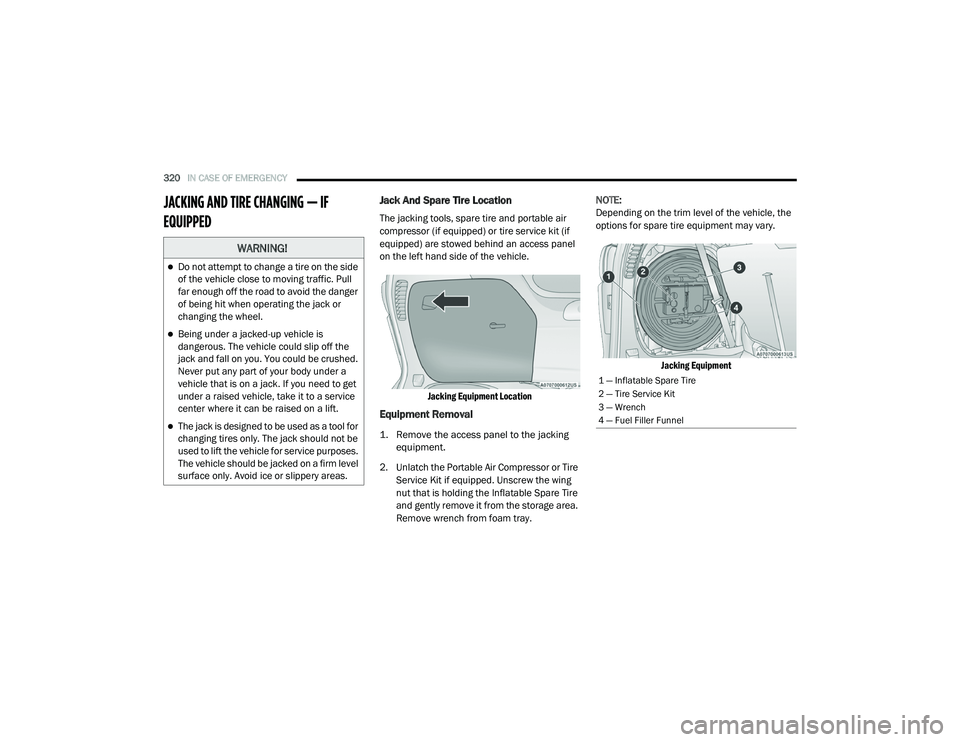
EQUIPPED Jack And Spare Tire Location
The jacking tools, spare tire and portable air
compressor (if equipped) or tire service kit (if
equipped) are stowed behind an access panel
on the left hand side of the vehicle.
Jacking Equipment Location
Equipment Removal
1. Remove the access panel to the jacking equipment.
2. Unlatch the Portable Air Compressor or Tire Service Kit if equipped. Unscrew the wing
nut that is holding the Inflatable Spare Tire
and gently remove it from the storage area.
Remove wrench from foam tray. NOTE:
Depending on the trim level of the vehicle, the
options for spare tire equipment may vary.
Jacking Equipment
WARNING!
Do not attempt to change a tire on the side
of the vehicle close to moving traffic. Pull
far enough off the road to avoid the danger
of being hit when operating the jack or
changing the wheel.
Being under a jacked-up vehicle is
dangerous. The vehicle could slip off the
jack and fall on you. You could be crushed.
Never put any part of your body under a
vehicle that is on a jack. If you need to get
under a raised vehicle, take it to a service
center where it can be raised on a lift.
The jack is designed to be used as a tool for
changing tires only. The jack should not be
used to lift the vehicle for service purposes.
The vehicle should be jacked on a firm level
surface only. Avoid ice or slippery areas.
1 — Inflatable Spare Tire
2 — Tire Service Kit
3 — Wrench
4 — Fuel Filler Funnel
20_RU_OM_EN_US_t.book Page 320
Page 323 of 516
IN CASE OF EMERGENCY321
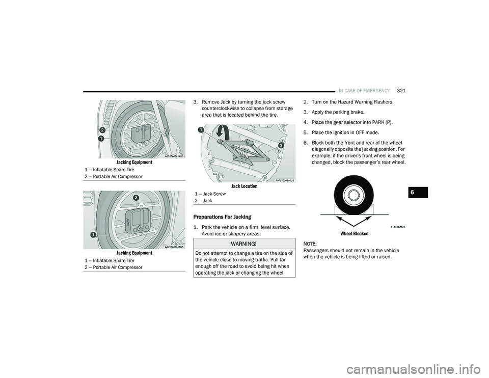
Jacking Equipment
Jacking Equipment
3. Remove Jack by turning the jack screw
counterclockwise to collapse from storage
area that is located behind the tire.
Jack Location
Preparations For Jacking
1. Park the vehicle on a firm, level surface. Avoid ice or slippery areas.
2. Turn on the Hazard Warning Flashers.
3. Apply the parking brake.
4. Place the gear selector into PARK (P).
5. Place the ignition in OFF mode.
6. Block both the front and rear of the wheel
diagonally opposite the jacking position. For
example, if the driver’s front wheel is being
changed, block the passenger’s rear wheel.
Wheel Blocked
NOTE:
Passengers should not remain in the vehicle
when the vehicle is being lifted or raised.
1 — Inflatable Spare Tire
2 — Portable Air Compressor
1 — Inflatable Spare Tire
2 — Portable Air Compressor
1 — Jack Screw
2 — Jack
WARNING!
Do not attempt to change a tire on the side of
the vehicle close to moving traffic. Pull far
enough off the road to avoid being hit when
operating the jack or changing the wheel.
6
20_RU_OM_EN_US_t.book Page 321
Page 324 of 516
322IN CASE OF EMERGENCY
(Continued)
Jacking Instructions
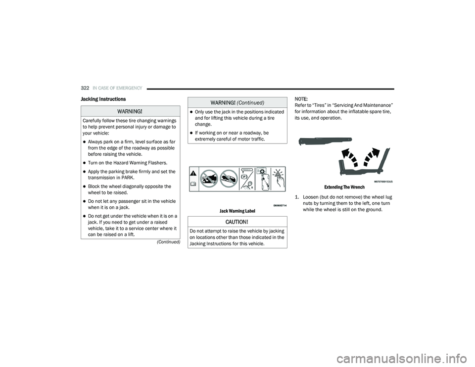
Jack Warning Label
NOTE:
Refer to “Tires” in “Servicing And Maintenance”
for information about the inflatable spare tire,
its use, and operation.
Extending The Wrench
1. Loosen (but do not remove) the wheel lug nuts by turning them to the left, one turn
while the wheel is still on the ground.
WARNING!
Carefully follow these tire changing warnings
to help prevent personal injury or damage to
your vehicle:
Always park on a firm, level surface as far
from the edge of the roadway as possible
before raising the vehicle.
Turn on the Hazard Warning Flashers.
Apply the parking brake firmly and set the
transmission in PARK.
Block the wheel diagonally opposite the
wheel to be raised.
Do not let any passenger sit in the vehicle
when it is on a jack.
Do not get under the vehicle when it is on a
jack. If you need to get under a raised
vehicle, take it to a service center where it
can be raised on a lift.
Only use the jack in the positions indicated
and for lifting this vehicle during a tire
change.
If working on or near a roadway, be
extremely careful of motor traffic.
CAUTION!
Do not attempt to raise the vehicle by jacking
on locations other than those indicated in the
Jacking Instructions for this vehicle.
WARNING! (Continued)
20_RU_OM_EN_US_t.book Page 322
Page 325 of 516
IN CASE OF EMERGENCY323
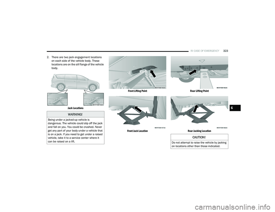
2. There are two jack engagement locations
on each side of the vehicle body. These
locations are on the sill flange of the vehicle
body.
Jack Locations Front Lifting Point
Front Jack Location Rear Lifting Point
Rear Jacking Location
WARNING!
Being under a jacked-up vehicle is
dangerous. The vehicle could slip off the jack
and fall on you. You could be crushed. Never
get any part of your body under a vehicle that
is on a jack. If you need to get under a raised
vehicle, take it to a service center where it
can be raised on a lift.
CAUTION!
Do not attempt to raise the vehicle by jacking
on locations other than those indicated.
6
20_RU_OM_EN_US_t.book Page 323
Page 326 of 516
324IN CASE OF EMERGENCY
3. Place the wrench on the jack screw and turn
clockwise until the jack head is properly
engaged in the described location. Do not
raise the vehicle until you are sure the jack
is securely engaged.
4. Raise the vehicle by turning the jack screw clockwise, using the swivel wrench. Raise
the vehicle only until the tire just clears the
surface and enough clearance is obtained
to install the compact spare tire. Minimum
tire lift provides maximum stability.
5. Remove the wheel lug nuts, for vehicles with wheel covers, remove the cover from
the wheel by hand. Do not pry the wheel
cover off. Then pull the wheel off the hub.
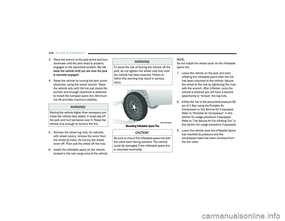
6. Install the inflatable spare on the vehicle, located in the rear cargo area of the vehicle.
Mounting Inflatable Spare Tire
NOTE:
Do not install the wheel cover on the inflatable
spare tire.
7. Leave the vehicle on the jack and start
inflating the inflatable spare after the tire
has been mounted to the vehicle. Secure
the wheel to the hub by tightening the nuts
with the wrench. After inflation, once the
vehicle is lowered you will have a second
opportunity to “torque” the lug nuts.
8. Inflate the tire to the prescribed pressure 60 psi (4.2 Bar) using the Portable Air
Compressor or Tire Service Kit if equipped.
Refer to “Portable Air Compressor” in this
section for usage procedure if equipped.
Refer to “Tire Service Kit For Inflating Tire” in
this section for usage procedure if equipped.
9. Lower the vehicle once the inflatable Spare has reached its pressure and the
compressor-hose has been removed from
the tire valve.
WARNING!
Raising the vehicle higher than necessary can
make the vehicle less stable. It could slip off
the jack and hurt someone near it. Raise the
vehicle only enough to remove the tire.
WARNING!
To avoid the risk of forcing the vehicle off the
jack, do not tighten the wheel nuts fully until
the vehicle has been lowered. Failure to
follow this warning may result in serious
injury.
CAUTION!
Be sure to mount the inflatable spare tire with
the valve stem facing outward. The vehicle
could be damaged if the inflatable spare tire
is mounted incorrectly.
20_RU_OM_EN_US_t.book Page 324
Page 327 of 516
IN CASE OF EMERGENCY325
10. Finish tightening the lug nuts. Push down on
the wrench while at the end of the handle
for increased leverage. Tighten the lug nuts
in a star pattern until each nut has been
tightened twice. Refer to “Wheel And Tire
Torque Specifications” in “Technical
Specifications” for proper wheel lug nut
torque. If in doubt about the correct
tightness, have them checked with a torque
wrench by an authorized dealer or at a
service station.
11. Lower the jack to its fully-closed position.
12. Place the deflated (flat) tire and foam tray cover assembly in the rear cargo area. Do
not stow the deflated tire in the inflatable
spare tire location. Have the full-sized tire
repaired or replaced, as soon as possible. 13. Stow the jack back in the stowage
compartment and place the access panel
back. The stud of the storage area must be
threaded through the lower part of the jack.
Then turn the Jack Screw clockwise to
secure it in place.
NOTE:
Stow the foam tray and components in the
cargo area.
Storing The Jack
Road Tire Installation
Vehicles Equipped With Wheel Covers
1. Mount the road tire on the axle.
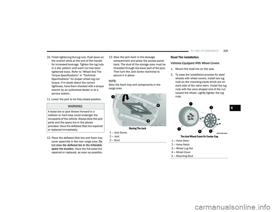
2. To ease the installation process for steel wheels with wheel covers, install two lug
nuts on the mounting studs which are on
each side of the valve stem. Install the lug
nuts with the cone shaped end of the nut
toward the wheel. Lightly tighten the lug
nuts.
Tire And Wheel Cover Or Center Cap
WARNING!
A loose tire or jack thrown forward in a
collision or hard stop could endanger the
occupants of the vehicle. Always stow the jack
parts and the spare tire in the places
provided. Have the deflated (flat) tire repaired
or replaced immediately.
1 — Jack Screw
2 — Jack
3 — Stud
1 — Valve Stem
2 — Valve Notch
3 — Wheel Lug Nut
4 — Wheel Cover
5 — Mounting Stud
6
20_RU_OM_EN_US_t.book Page 325