tow CHRYSLER PACIFICA HYBRID 2021 Owners Manual
[x] Cancel search | Manufacturer: CHRYSLER, Model Year: 2021, Model line: PACIFICA HYBRID, Model: CHRYSLER PACIFICA HYBRID 2021Pages: 401, PDF Size: 26.88 MB
Page 328 of 401
326IN CASE OF EMERGENCY
NOTE:The Safehold feature will engage the Electric Park
Brake whenever the driver's door is opened (if the
ignition is ON, transmission is not in PARK, and
brake pedal is released). If you are towing this
vehicle with the ignition in the ON/RUN mode, you
must manually disable the Electric Park Brake
each time the driver's door is opened, by pressing
the brake pedal and then releasing the EPB.
If the key fob is unavailable or the vehicle's battery
is discharged, detailed instructions on shifting the
transmission out of PARK in order to move the
vehicle Úpage 321.
ALL WHEEL DRIVE (AWD) MODELS
FCA US LLC recommends towing your vehicle with
all four wheels OFF the ground using a flatbed.
ENHANCED ACCIDENT RESPONSE SYSTEM
(EARS)
This vehicle is equipped with an Enhanced
Accident Response System.
This feature is a communication network that
takes effect in the event of an impact. Detailed
information can be found on Ú page 272.
EVENT DATA RECORDER (EDR)
This vehicle is equipped with an event data
recorder (EDR). The main purpose of an EDR is to
record data that will assist in understanding how a
vehicle’s systems performed under certain crash
or near crash-like situations, such as an air bag
deployment or hitting a road obstacle. Detailed
information can be found on Úpage 274.
CAUTION!
Do not use sling-type equipment when towing.
Vehicle damage may occur.
When securing the vehicle to a flatbed truck,
do not attach to front or rear suspension
components. Damage to your vehicle may
result from improper towing.
Ensure that the Electric Park Brake is
released, and remains released, while being
towed.
CAUTION!
Towing this vehicle using any other method
can cause severe transmission and/or
transfer case damage.
Damage from improper towing is not covered
under the New Vehicle Limited Warranty.
21_RUP_OM_EN_USC_t.book Page 326
Page 329 of 401
327
SERVICING AND MAINTENANCE
SCHEDULED SERVICING
Your vehicle is equipped with an automatic oil
change indicator system. The oil change indicator
system will remind you that it is time to take your
vehicle in for scheduled maintenance.
Based on engine operation conditions, the oil
change indicator message will illuminate. This
means that service is required for your vehicle.
Operating conditions such as frequent short-trips,
trailer tow, extremely hot or cold ambient
temperatures will influence when the “Oil Change
Required” message is displayed. Have your vehicle
serviced as soon as possible, within the next
500 miles (805 km).An authorized dealer will reset the oil change
indicator message after completing the scheduled
oil change. If a scheduled oil change is performed
by someone other than an authorized dealer
Ú
page 113.
NOTE:Under no circumstances should oil change
intervals exceed 10,000 miles (16,000 km),
12 months or 350 hours of engine run time,
whichever comes first. The 350 hours of engine
run or idle time is generally only a concern for fleet
customers. Once A Month Or Before A Long Trip:
Check engine oil level.
Check windshield washer fluid level.
Check tire pressure and look for unusual wear
or damage. Rotate tires at the first sign of
irregular wear, even if it occurs before the oil
indicator system turns on.
Check the fluid levels of the coolant reservoir
and brake master cylinder, fill as needed.
Check function of all interior and exterior lights.
8
21_RUP_OM_EN_USC_t.book Page 327
Page 334 of 401
332SERVICING AND MAINTENANCE
(Continued)
CHECKING OIL LEVEL
To ensure proper engine lubrication, the engine oil
must be maintained at the correct level. Check the
oil level at regular intervals, such as every fuel
stop. The best time to check the engine oil level is
about five minutes after a fully warmed up engine
is shut off.
Checking the oil while the vehicle is on level ground
will improve the accuracy of the oil level readings.
There are four possible dipstick types:
Crosshatched zone.
Crosshatched zone marked SAFE.
Crosshatched zone marked with MIN at the low
end of the range and MAX at the high end of the
range.
Crosshatched zone marked with dimples at the
MIN and the MAX ends of the range.
NOTE:Always maintain the oil level within the crosshatch
markings on the dipstick.
Adding 1 quart (1.0 liter) of oil when the reading is
at the low end of the dipstick range will raise the oil
level to the high end of the range marking.
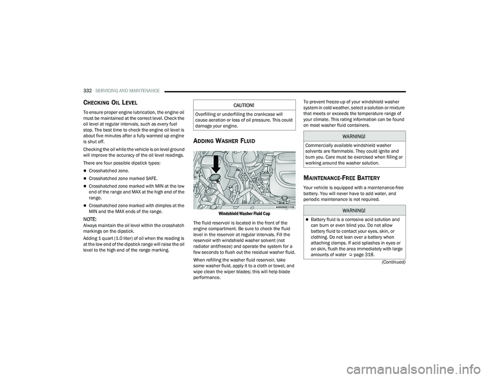
ADDING WASHER FLUID
Windshield Washer Fluid Cap
The fluid reservoir is located in the front of the
engine compartment. Be sure to check the fluid
level in the reservoir at regular intervals. Fill the
reservoir with windshield washer solvent (not
radiator antifreeze) and operate the system for a
few seconds to flush out the residual washer fluid.
When refilling the washer fluid reservoir, take
some washer fluid, apply it to a cloth or towel, and
wipe clean the wiper blades; this will help blade
performance. To prevent freeze-up of your windshield washer
system in cold weather, select a solution or mixture
that meets or exceeds the temperature range of
your climate. This rating information can be found
on most washer fluid containers.
MAINTENANCE-FREE BATTERY
Your vehicle is equipped with a maintenance-free
battery. You will never have to add water, and
periodic maintenance is not required.
CAUTION!
Overfilling or underfilling the crankcase will
cause aeration or loss of oil pressure. This could
damage your engine.
WARNING!
Commercially available windshield washer
solvents are flammable. They could ignite and
burn you. Care must be exercised when filling or
working around the washer solution.
WARNING!
Battery fluid is a corrosive acid solution and
can burn or even blind you. Do not allow
battery fluid to contact your eyes, skin, or
clothing. Do not lean over a battery when
attaching clamps. If acid splashes in eyes or
on skin, flush the area immediately with large
amounts of water Ú
page 318.
21_RUP_OM_EN_USC_t.book Page 332
Page 339 of 401
SERVICING AND MAINTENANCE337
5. Pry up the lid of each individual compartment snap, and detach it from the rest of the snap.
There is a small space on the side of each
snap to use for separating the lid from the
snap. Once detached, remove the rest of the
snap completely from the compartment cover.
6. After removing the snaps, lift up the compartment cover to gain access to the fresh
air inlet.
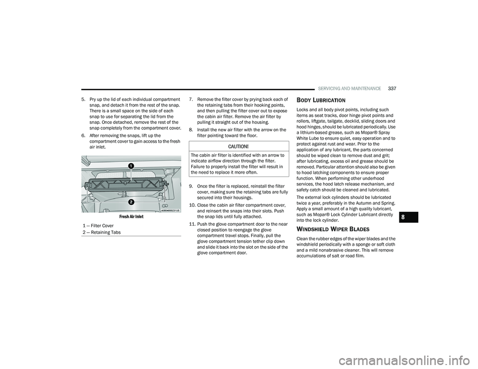
Fresh Air Inlet
7. Remove the filter cover by prying back each of
the retaining tabs from their hooking points,
and then pulling the filter cover out to expose
the cabin air filter. Remove the air filter by
pulling it straight out of the housing.
8. Install the new air filter with the arrow on the filter pointing toward the floor.
9. Once the filter is replaced, reinstall the filter cover, making sure the retaining tabs are fully
secured into their housings.
10. Close the cabin air filter compartment cover, and reinsert the snaps into their slots. Push
the snap lids until fully attached.
11. Push the glove compartment door to the near closed position to reengage the glove
compartment travel stops. Finally, pull the
glove compartment tension tether clip down
and slide it back into the slot on the side of the
glove compartment door.
BODY LUBRICATION
Locks and all body pivot points, including such
items as seat tracks, door hinge pivot points and
rollers, liftgate, tailgate, decklid, sliding doors and
hood hinges, should be lubricated periodically. Use
a lithium-based grease, such as Mopar® Spray
White Lube to ensure quiet, easy operation and to
protect against rust and wear. Prior to the
application of any lubricant, the parts concerned
should be wiped clean to remove dust and grit;
after lubricating, excess oil and grease should be
removed. Particular attention should also be given
to hood latching components to ensure proper
function. When performing other underhood
services, the hood latch release mechanism, and
safety catch should be cleaned and lubricated.
The external lock cylinders should be lubricated
twice a year, preferably in the Autumn and Spring.
Apply a small amount of a high quality lubricant,
such as Mopar® Lock Cylinder Lubricant directly
into the lock cylinder.
WINDSHIELD WIPER BLADES
Clean the rubber edges of the wiper blades and the
windshield periodically with a sponge or soft cloth
and a mild nonabrasive cleaner. This will remove
accumulations of salt or road film.
1 — Filter Cover
2 — Retaining Tabs
CAUTION!
The cabin air filter is identified with an arrow to
indicate airflow direction through the filter.
Failure to properly install the filter will result in
the need to replace it more often.
8
21_RUP_OM_EN_USC_t.book Page 337
Page 340 of 401
338SERVICING AND MAINTENANCE
Operation of the wipers on dry glass for long
periods may cause deterioration of the wiper
blades. Always use washer fluid when using the
wipers to remove salt or dirt from a dry windshield.
Avoid using the wiper blades to remove frost or ice
from the windshield. Keep the blade rubber out of
contact with petroleum products such as engine
oil, gasoline, etc.
NOTE:Life expectancy of wiper blades varies depending
on geographical area and frequency of use. If chat -
tering, marks, water lines or wet spots are present,
clean the wiper blades or replace as necessary.
The wiper blades and wiper arms should be
inspected periodically, not just when wiper
performance problems are experienced. This
inspection should include the following points:
Wear or uneven edges
Foreign material
Hardening or cracking
Deformation or fatigue
If a wiper blade or wiper arm is damaged, replace
the affected wiper arm or blade with a new unit. Do
not attempt to repair a wiper arm or blade that is
damaged.
Front Wiper Blade Removal/Installation
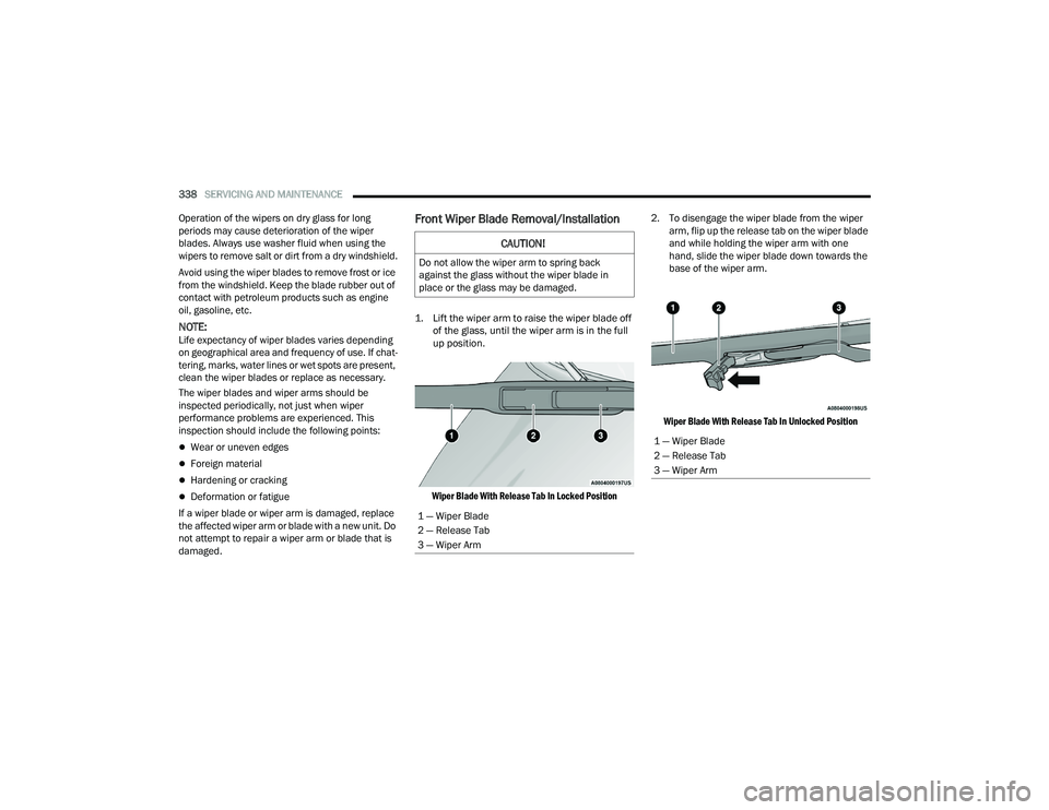
1. Lift the wiper arm to raise the wiper blade off of the glass, until the wiper arm is in the full
up position.
Wiper Blade With Release Tab In Locked Position
2. To disengage the wiper blade from the wiper
arm, flip up the release tab on the wiper blade
and while holding the wiper arm with one
hand, slide the wiper blade down towards the
base of the wiper arm.
Wiper Blade With Release Tab In Unlocked Position
CAUTION!
Do not allow the wiper arm to spring back
against the glass without the wiper blade in
place or the glass may be damaged.
1 — Wiper Blade
2 — Release Tab
3 — Wiper Arm
1 — Wiper Blade
2 — Release Tab
3 — Wiper Arm
21_RUP_OM_EN_USC_t.book Page 338
Page 341 of 401
SERVICING AND MAINTENANCE339
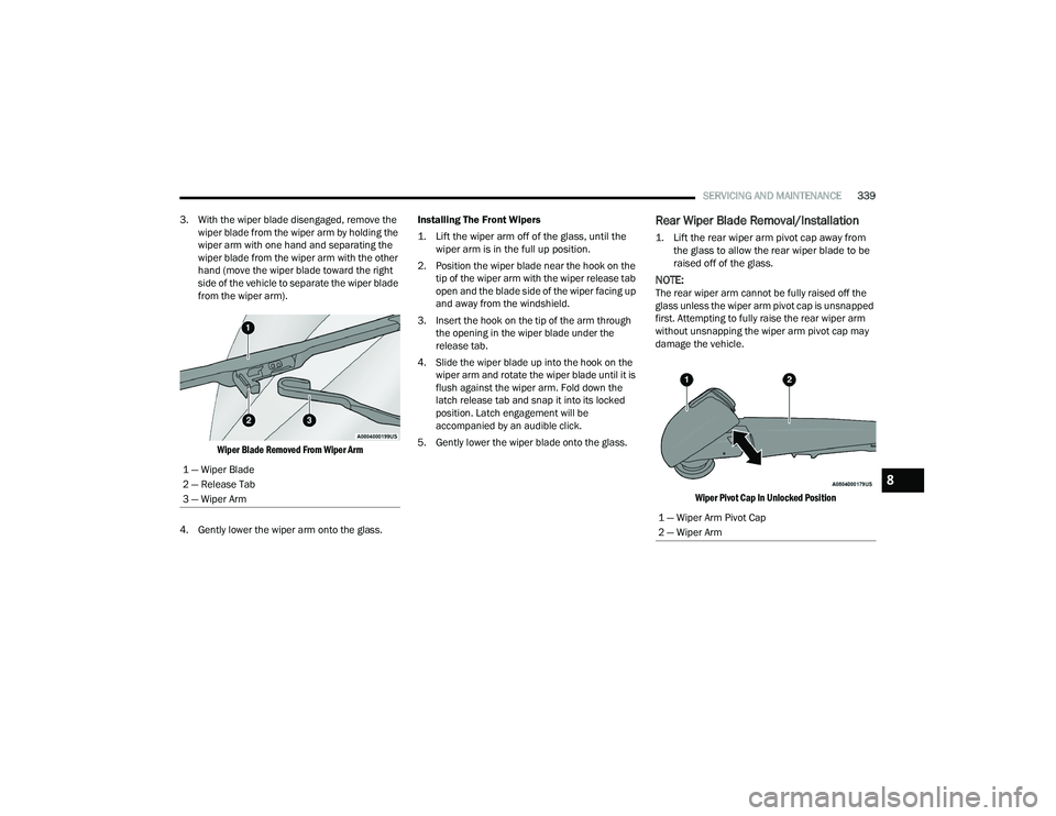
3. With the wiper blade disengaged, remove the wiper blade from the wiper arm by holding the
wiper arm with one hand and separating the
wiper blade from the wiper arm with the other
hand (move the wiper blade toward the right
side of the vehicle to separate the wiper blade
from the wiper arm).
Wiper Blade Removed From Wiper Arm
4. Gently lower the wiper arm onto the glass. Installing The Front Wipers
1. Lift the wiper arm off of the glass, until the
wiper arm is in the full up position.
2. Position the wiper blade near the hook on the tip of the wiper arm with the wiper release tab
open and the blade side of the wiper facing up
and away from the windshield.
3. Insert the hook on the tip of the arm through the opening in the wiper blade under the
release tab.
4. Slide the wiper blade up into the hook on the wiper arm and rotate the wiper blade until it is
flush against the wiper arm. Fold down the
latch release tab and snap it into its locked
position. Latch engagement will be
accompanied by an audible click.
5. Gently lower the wiper blade onto the glass.
Rear Wiper Blade Removal/Installation
1. Lift the rear wiper arm pivot cap away from the glass to allow the rear wiper blade to be
raised off of the glass.
NOTE:The rear wiper arm cannot be fully raised off the
glass unless the wiper arm pivot cap is unsnapped
first. Attempting to fully raise the rear wiper arm
without unsnapping the wiper arm pivot cap may
damage the vehicle.
Wiper Pivot Cap In Unlocked Position
1 — Wiper Blade
2 — Release Tab
3 — Wiper Arm
1 — Wiper Arm Pivot Cap
2 — Wiper Arm
8
21_RUP_OM_EN_USC_t.book Page 339
Page 343 of 401
SERVICING AND MAINTENANCE341
(Continued)
EXHAUST SYSTEM
The best protection against carbon monoxide entry
into the vehicle body is a properly maintained
engine exhaust system.
If you notice a change in the sound of the exhaust
system; or if the exhaust fumes can be detected
inside the vehicle; or when the underside or rear of
the vehicle is damaged; have an authorized
technician inspect the complete exhaust system
and adjacent body areas for broken, damaged,
deteriorated, or mispositioned parts. Open seams
or loose connections could permit exhaust fumes
to seep into the passenger compartment. In
addition, have the exhaust system inspected each
time the vehicle is raised for lubrication or oil
change. Replace as required. Under normal operating conditions, the catalytic
converter will not require maintenance. However, it
is important to keep the engine properly tuned to
ensure proper catalyst operation and prevent
possible catalyst damage.
NOTE:Intentional tampering with emissions control
systems can result in civil penalties being
assessed against you.
In unusual situations involving grossly
malfunctioning engine operation, a scorching odor
may suggest severe and abnormal catalyst
overheating. If this occurs, stop the vehicle, turn off
the engine and allow it to cool. Service, including a
tune-up to the manufacturer specifications, should
be obtained immediately.
To minimize the possibility of catalytic converter
damage:
Do not interrupt the ignition when the transmis
-
sion is in gear and the vehicle is in motion.
Do not try to start the vehicle by pushing or
towing the vehicle.
Do not idle the engine with any ignition compo -
nents disconnected or removed, such as when
diagnostic testing, or for prolonged periods
during very rough idle or malfunctioning oper -
ating conditions.
WARNING!
Exhaust gases can injure or kill. They contain
Carbon Monoxide (CO), which is colorless and
odorless. Breathing it can make you uncon -
scious and can eventually poison you
Ú page 291.
A hot exhaust system can start a fire if you
park over materials that can burn, such as
grass or leaves, and those items can come
into contact with your exhaust system. Do not
park or operate your vehicle in areas where
your exhaust system can contact anything that
can burn.
CAUTION!
The catalytic converter requires the use of
unleaded fuel only. Leaded gasoline will
destroy the effectiveness of the catalyst as an
emissions control device and may seriously
reduce engine performance and cause
serious damage to the engine.
Damage to the catalytic converter can result if
your vehicle is not kept in proper operating
condition. In the event of engine malfunction,
particularly involving engine misfire or other
apparent loss of performance, have your
vehicle serviced promptly. Continued opera -
tion of your vehicle with a severe malfunction
could cause the converter to overheat,
resulting in possible damage to the converter
and vehicle.
WARNING!
8
21_RUP_OM_EN_USC_t.book Page 341
Page 353 of 401
SERVICING AND MAINTENANCE351
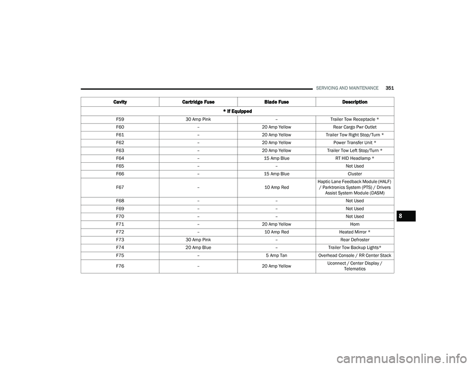
F59 30 Amp Pink –Trailer Tow Receptacle *
F60 –20 Amp Yellow Rear Cargo Pwr Outlet
F61 –20 Amp YellowTrailer Tow Right Stop/Turn *
F62 –20 Amp Yellow Power Transfer Unit *
F63 –20 Amp Yellow Trailer Tow Left Stop/Turn *
F64 –15 Amp Blue RT HID Headlamp *
F65 ––Not Used
F66 –15 Amp Blue Cluster
F67 –10 Amp RedHaptic Lane Feedback Module (HALF)
/ Parktronics System (PTS) / Drivers Assist System Module (DASM)
F68 ––Not Used
F69 ––Not Used
F70 ––Not Used
F71 –20 Amp Yellow Horn
F72 –10 Amp Red Heated Mirror *
F73 30 Amp Pink –Rear Defroster
F74 20 Amp Blue –Trailer Tow Backup Lights*
F75 –5 Amp TanOverhead Console / RR Center Stack
F76 –20 Amp Yellow Uconnect / Center Display /
Telematics
Cavity Cartridge Fuse Blade FuseDescription
* If Equipped
8
21_RUP_OM_EN_USC_t.book Page 351
Page 355 of 401
SERVICING AND MAINTENANCE353
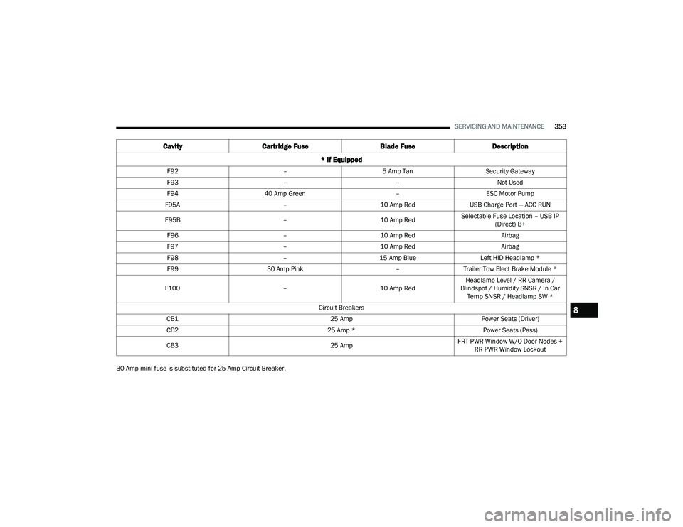
30 Amp mini fuse is substituted for 25 Amp Circuit Breaker. F92
–5 Amp Tan Security Gateway
F93 ––Not Used
F94 40 Amp Green –ESC Motor Pump
F95A –10 Amp RedUSB Charge Port — ACC RUN
F95B –10 Amp RedSelectable Fuse Location – USB IP
(Direct) B+
F96 –10 Amp Red Airbag
F97 –10 Amp Red Airbag
F98 –15 Amp Blue Left HID Headlamp *
F99 30 Amp Pink –Trailer Tow Elect Brake Module *
F100 –10 Amp RedHeadlamp Level / RR Camera /
Blindspot / Humidity SNSR / In Car Temp SNSR / Headlamp SW *
Circuit Breakers
CB1 25 AmpPower Seats (Driver)
CB2 25 Amp *Power Seats (Pass)
CB3 25 AmpFRT PWR Window W/O Door Nodes +
RR PWR Window Lockout
Cavity Cartridge Fuse Blade FuseDescription
* If Equipped
8
21_RUP_OM_EN_USC_t.book Page 353
Page 362 of 401
360SERVICING AND MAINTENANCE
Tire Loading And Tire Pressure
NOTE:The proper cold tire inflation pressure is listed on
the driver’s side B-pillar or the rear edge of the
driver's side door.
Check the inflation pressure of each tire, including
the spare tire (if equipped), at least monthly and
inflate to the recommended pressure for your
vehicle.
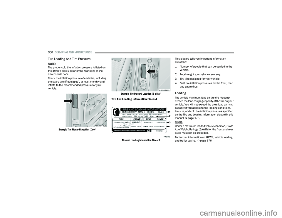
Example Tire Placard Location (Door) Example Tire Placard Location (B-pillar)
Tire And Loading Information Placard
Tire And Loading Information Placard
This placard tells you important information
about the:
1. Number of people that can be carried in the
vehicle.
2. Total weight your vehicle can carry.
3. Tire size designed for your vehicle.
4. Cold tire inflation pressures for the front, rear, and spare tires.
Loading
The vehicle maximum load on the tire must not
exceed the load carrying capacity of the tire on your
vehicle. You will not exceed the tire's load carrying
capacity if you adhere to the loading conditions,
tire size, and cold tire inflation pressures specified
on the Tire and Loading Information placard in this
manual Ú page 176.
NOTE:Under a maximum loaded vehicle condition, Gross
Axle Weight Ratings (GAWR) for the front and rear
axles must not be exceeded.
For further information on GAWR, vehicle loading,
and trailer towing, Ú page 176.
21_RUP_OM_EN_USC_t.book Page 360