ECU CHRYSLER PACIFICA HYBRID 2022 Service Manual
[x] Cancel search | Manufacturer: CHRYSLER, Model Year: 2022, Model line: PACIFICA HYBRID, Model: CHRYSLER PACIFICA HYBRID 2022Pages: 384, PDF Size: 23.92 MB
Page 266 of 384
264SAFETY
Older Children And Child Restraints
Children who are two years old or who have
outgrown their rear-facing convertible child seat
can ride forward-facing in the vehicle.
Forward-facing child seats and convertible child
seats used in the forward-facing direction are for
children who are over two years old or who have
outgrown the rear-facing weight or height limit of
their rear-facing convertible child seat. Children
should remain in a forward-facing child seat with a
harness for as long as possible, up to the highest
weight or height allowed by the child seat.
All children whose weight or height is above the
forward-facing limit for the child seat should use a
belt-positioning booster seat until the vehicle’s
seat belts fit properly. If the child cannot sit with
knees bent over the vehicle’s seat cushion while
the child’s back is against the seatback, they
should use a belt-positioning booster seat. The
child and belt-positioning booster seat are held in
the vehicle by the seat belt.WARNING!
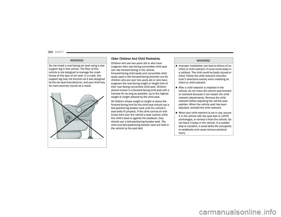
Do not install a rear-facing car seat using a rear
support leg in this vehicle. The floor of this
vehicle is not designed to manage the crash
forces of this type of car seat. In a crash, the
support leg may not function as it was designed
by the car seat manufacturer, and your child may
be more severely injured as a result.
WARNING!
Improper installation can lead to failure of an
infant or child restraint. It could come loose in
a collision. The child could be badly injured or
killed. Follow the child restraint manufac -
turer’s directions exactly when installing an
infant or child restraint.
After a child restraint is installed in the
vehicle, do not move the vehicle seat forward
or rearward because it can loosen the child
restraint attachments. Remove the child
restraint before adjusting the vehicle seat
position. When the vehicle seat has been
adjusted, reinstall the child restraint.
When your child restraint is not in use, secure
it in the vehicle with the seat belt or LATCH
anchorages, or remove it from the vehicle. Do
not leave it loose in the vehicle. In a sudden
stop or accident, it could strike the occupants
or seatbacks and cause serious personal
injury.
22_RUP_OM_EN_USC_t.book Page 264
Page 274 of 384
272SAFETY
(Continued)
How To Stow An Unused Switchable-ALR
(ALR) Seat Belt:
When using the LATCH attaching system to install
a child restraint, stow all ALR seat belts that are not
being used by other occupants or being used to
secure child restraints. An unused belt could injure
a child if they play with it and accidentally lock the
seat belt retractor. Before installing a child
restraint using the LATCH system, buckle the seat
belt behind the child restraint and out of the child’s
reach. If the buckled seat belt interferes with the
child restraint installation, instead of buckling it
behind the child restraint, route the seat belt
through the child restraint belt path and then
buckle it. Do not lock the seat belt. Remind all
children in the vehicle that the seat belts are not
toys and that they should not play with them.
Installing Child Restraints Using The
Vehicle Seat Belt
Child restraint systems are designed to be secured
in vehicle seats by lap belts or the lap belt portion
of a lap/shoulder belt. The seat belts in the passenger seating positions
are equipped with a Switchable Automatic Locking
Retractor (ALR) that is designed to keep the lap
portion of the seat belt tight around the child
restraint so that it is not necessary to use a locking
clip. The ALR retractor can be “switched” into a
locked mode by pulling all of the webbing out of the
retractor and then letting the webbing retract back
into the retractor. If it is locked, the ALR will make
a clicking noise while the webbing is pulled back
into the retractor.
See the “Automatic Locking Mode” description for
additional information on ALR Ú
page 247.
Please see the table below and the following
sections for more information.
WARNING!
Improper installation of a child restraint to the
LATCH anchorages can lead to failure of the
restraint. The child could be badly injured or
killed. Follow the child restraint manufac -
turer’s directions exactly when installing an
infant or child restraint.
Child restraint anchorages are designed to
withstand only those loads imposed by
correctly-fitted child restraints. Under no
circumstances are they to be used for adult
seat belts, harnesses, or for attaching other
items or equipment to the vehicle.
WARNING!
Improper installation or failure to properly
secure a child restraint can lead to failure of
the restraint. The child could be badly injured
or killed.
Follow the child restraint manufacturer’s
directions exactly when installing an infant or
child restraint.
WARNING!
22_RUP_OM_EN_USC_t.book Page 272
Page 277 of 384
SAFETY275
(Continued)
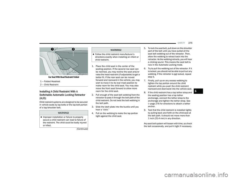
Car Seat With Head Restraint Folded
Installing A Child Restraint With A
Switchable Automatic Locking Retractor
(ALR):
Child restraint systems are designed to be secured
in vehicle seats by lap belts or the lap belt portion
of a lap/shoulder belt.
1. Place the child seat in the center of the
seating position. If the second row seat can
be reclined, you may recline the seat and/or
raise the head restraint (if adjustable) to get a
better fit. If the rear seat can be moved
forward and rearward in the vehicle, you may
wish to move it to its rear-most position to
make room for the child seat. You may also
move the front seat forward to allow more
room for the child seat.
2. Pull enough of the seat belt webbing from the retractor to pass it through the belt path of the
child restraint. Do not twist the belt webbing in
the belt path.
3. Slide the latch plate into the buckle until you hear a “click.”
4. Pull on the webbing to make the lap portion tight against the child seat. 5. To lock the seat belt, pull down on the shoulder
part of the belt until you have pulled all the
seat belt webbing out of the retractor. Then,
allow the webbing to retract back into the
retractor. As the webbing retracts, you will hear
a clicking sound. This means the seat belt is
now in the Automatic Locking mode.
6. Try to pull the webbing out of the retractor. If it is locked, you should not be able to pull out any
webbing. If the retractor is not
locked, repeat
step 5.
7. Finally, pull up on any excess webbing to tighten the lap portion around the child
restraint while you push the child restraint
rearward and downward into the vehicle seat.
8. If the child restraint has a top tether strap and the seating position has a top tether
anchorage, connect the tether strap to the
anchorage and tighten the tether strap. See
Úpage 276 for directions to attach a tether
anchor.
9. Test that the child restraint is installed tightly by pulling back and forth on the child seat at
the belt path. It should not move more than
1 inch (25.4 mm) in any direction.
Any seat belt system will loosen with time, so check
the belt occasionally, and pull it tight if necessary.
1 — Folded Headrest
2 — Child Restraint
WARNING!
Improper installation or failure to properly
secure a child restraint can lead to failure of
the restraint. The child could be badly injured
or killed.
Follow the child restraint manufacturer’s
directions exactly when installing an infant or
child restraint.
WARNING!
6
22_RUP_OM_EN_USC_t.book Page 275
Page 278 of 384
276SAFETY
Seat Belt Park Stitch — If Equipped
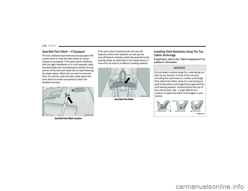
The rear outboard seat belts may be equipped with
a park stitch to raise the latch plate for easier
access to occupants. If the park stitch interferes
with the tight installation of a child restraint, slide
the latch plate over the stitching to shorten the lap
portion of the belt and install the car seat following
the steps above. When the car seat is removed
from the vehicle, slide the latch plate above the
park stitch to enable occupants to latch the
seatbelt securely.
Seat Belt Park Stitch Location
If the park stitch interferes with the lock-off
features of the child restraint, do not use the
lock-off feature. Instead, switch the seat belt to the
locking mode, as described in the steps above or
move the car seat to a different seating position.
Seat Belt Park Stitch
Installing Child Restraints Using The Top
Tether Anchorage
If applicable, refer to the “Hybrid Supplement” for
additional information.
WARNING!
Do not attach a tether strap for a rear-facing car
seat to any location in front of the car seat,
including the seat frame or a tether anchorage.
Only attach the tether strap of a rear-facing car
seat to the tether anchorage that is approved for
that seating position, located behind the top of
the vehicle seat. See Ú page 266 for the
location of approved tether anchorages in your
vehicle.
22_RUP_OM_EN_USC_t.book Page 276
Page 280 of 384
278SAFETY
Third Row Tether Attachment
The tether anchorage found on the back of the
60% seat in the third row may be used by either the
left outboard or the center seating position. Only
tether one child restraint to the tether anchorage
at a time.
To connect the tether strap hook to the tether
anchorage for either seating position on the 60%
third row seat:
1. Route the tether strap to provide the most
direct path for the strap between the anchor
and the child seat.
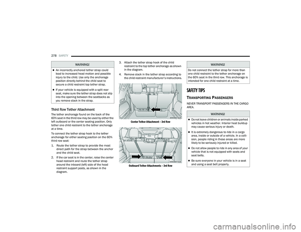
2. If the car seat is in the center, raise the center head restraint and route the tether strap
around the inboard (left) side of the head
restraint support posts, as shown in the
diagram. 3. Attach the tether strap hook of the child
restraint to the top tether anchorage as shown
in the diagram.
4. Remove slack in the tether strap according to the child restraint manufacturer’s instructions.
Center Tether Attachment – 3rd Row
Outboard Tether Attachments – 3rd Row
SAFETY TIPS
TRANSPORTING PASSENGERS
NEVER TRANSPORT PASSENGERS IN THE CARGO
AREA.
WARNING!
An incorrectly anchored tether strap could
lead to increased head motion and possible
injury to the child. Use only the anchorage
position directly behind the child seat to
secure a child restraint top tether strap.
If your vehicle is equipped with a split rear
seat, make sure the tether strap does not slip
into the opening between the seatbacks as
you remove slack in the strap.
WARNING!
Do not connect the tether strap for more than
one child restraint to the tether anchorage on
the 60% seat in the third row. This anchorage is
intended for one child restraint at a time.
WARNING!
Do not leave children or animals inside parked
vehicles in hot weather. Interior heat buildup
may cause serious injury or death.
It is extremely dangerous to ride in a cargo
area, inside or outside of a vehicle. In a colli -
sion, people riding in these areas are more
likely to be seriously injured or killed.
Do not allow people to ride in any area of your
vehicle that is not equipped with seats and
seat belts.
Be sure everyone in your vehicle is in a seat
and using a seat belt properly.
22_RUP_OM_EN_USC_t.book Page 278
Page 281 of 384
SAFETY279
TRANSPORTING PETS
Air Bags deploying in the front seat could harm
your pet. An unrestrained pet will be thrown about
and possibly injured, or injure a passenger during
panic braking or in a collision.
Pets should be restrained in the rear seat (if
equipped) in pet harnesses or pet carriers that are
secured by seat belts.
CONNECTED VEHICLES
Privacy of any wireless and wired communications
cannot be assured. Third parties may unlawfully
intercept information and private communications
without your consent. For further information, refer
to “Data Collection & Privacy” in your Uconnect
Owner’s Manual Supplement or “Onboard
Diagnostic System (OBD II) Cybersecurity”
Úpage 129.
SAFETY CHECKS YOU SHOULD MAKE
I
NSIDE THE VEHICLE
Seat Belts
Inspect the seat belt system periodically, checking
for cuts, frays, and loose parts. Damaged parts
must be replaced immediately. Do not
disassemble or modify the system.
If your vehicle is involved in a collision, or if you
have questions regarding seat belt or retractor
conditions, take your vehicle to an authorized FCA
dealer or authorized FCA Certified Collision Care
Program facility for inspection.
Air Bag Warning Light
The Air Bag Warning Light will turn on for
four to eight seconds as a bulb check
when the ignition switch is first placed in
the ON/RUN mode. If the light is either
not on during starting, stays on, or turns on while
driving, have the system inspected at an
authorized dealer as soon as possible. After the
bulb check, this light will illuminate with a single
chime when a fault with the Air Bag System has
been detected. It will stay on until the fault is removed. If the light
comes on intermittently or remains on while
driving, have an authorized dealer service the
vehicle immediately Ú
page 239.
Defroster
Check operation by selecting the defrost mode and
place the blower control on high speed. You should
be able to feel the air directed against the
windshield. See an authorized dealer for service if
your defroster is inoperable.
Floor Mat Safety Information
Always use floor mats designed to fit your vehicle.
Only use a floor mat that does not interfere with the
operation of the accelerator, brake or clutch
pedals. Only use a floor mat that is securely
attached using the floor mat fasteners so it cannot
slip out of position and interfere with the
accelerator, brake or clutch pedals or impair safe
operation of your vehicle in other ways.
WARNING!
It is not possible to know or to predict all of the
possible outcomes if your vehicle’s systems are
breached. It may be possible that vehicle
systems, including safety related systems, could
be impaired or a loss of vehicle control could
occur that may result in an accident involving
serious injury or death.
6
22_RUP_OM_EN_USC_t.book Page 279
Page 282 of 384
280SAFETY
(Continued)
(Continued)
PERIODIC SAFETY CHECKS YOU SHOULD
M
AKE OUTSIDE THE VEHICLE
Tires
Examine tires for excessive tread wear and uneven
wear patterns. Check for stones, nails, glass, or
other objects lodged in the tread or sidewall.
Inspect the tread for cuts and cracks. Inspect
sidewalls for cuts, cracks, and bulges. Check the
lug nut/bolt torque for tightness. Check the tires
(including spare) for proper cold inflation pressure.
WARNING!
An improperly attached, damaged, folded, or
stacked floor mat, or damaged floor mat
fasteners may cause your floor mat to interfere
with the accelerator, brake, or clutch pedals and
cause a loss of vehicle control. To prevent
SERIOUS INJURY or DEATH:
ALWAYS securely attach your floor
mat using the floor mat fasteners.
DO NOT install your floor mat upside
down or turn your floor mat over.
Lightly pull to confirm mat is secured using the
floor mat fasteners on a regular basis.
ALWAYS REMOVE THE EXISTING
FLOOR MAT FROM THE VEHICLE
before installing any other floor mat.
NEVER install or stack an additional
floor mat on top of an existing floor mat.
ONLY install floor mats designed to fit your
vehicle. NEVER install a floor mat that cannot
be properly attached and secured to your
vehicle. If a floor mat needs to be replaced,
only use a FCA US LLC approved floor mat for
the specific make, model, and year of your
vehicle.
ONLY use the driver’s side floor mat on the
driver’s side floor area. To check for interfer -
ence, with the vehicle properly parked with the
engine off, fully depress the accelerator, the
brake, and the clutch pedal (if present) to
check for interference. If your floor mat inter -
feres with the operation of any pedal, or is not
secure to the floor, remove the floor mat from
the vehicle and place the floor mat in your
trunk.
ONLY use the passenger’s side floor mat on
the passenger’s side floor area.
ALWAYS make sure objects cannot fall or slide
into the driver’s side floor area when the
vehicle is moving. Objects can become
trapped under accelerator, brake, or clutch
pedals and could cause a loss of vehicle
control.
NEVER place any objects under the floor mat
(e.g., towels, keys, etc.). These objects could
change the position of the floor mat and may
cause interference with the accelerator,
brake, or clutch pedals.
WARNING!
If the vehicle carpet has been removed and
re-installed, always properly attach carpet to
the floor and check the floor mat fasteners are
secure to the vehicle carpet. Fully depress
each pedal to check for interference with the
accelerator, brake, or clutch pedals then
re-install the floor mats.
It is recommended to only use mild soap and
water to clean your floor mats. After cleaning,
always check your floor mat has been properly
installed and is secured to your vehicle using
the floor mat fasteners by lightly pulling mat.
WARNING!
22_RUP_OM_EN_USC_t.book Page 280
Page 292 of 384
290IN CASE OF EMERGENCY
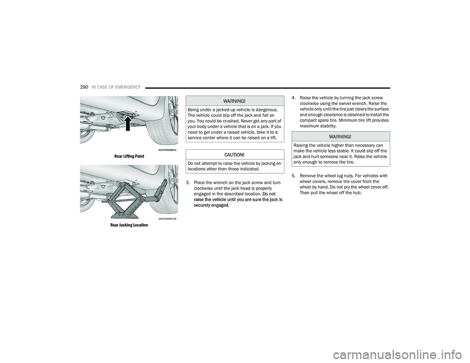
Rear Lifting Point
Rear Jacking Location
3. Place the wrench on the jack screw and turn
clockwise until the jack head is properly
engaged in the described location. Do not
raise the vehicle until you are sure the jack is
securely engaged. 4. Raise the vehicle by turning the jack screw
clockwise using the swivel wrench. Raise the
vehicle only until the tire just clears the surface
and enough clearance is obtained to install the
compact spare tire. Minimum tire lift provides
maximum stability.
5. Remove the wheel lug nuts. For vehicles with wheel covers, remove the cover from the
wheel by hand. Do not pry the wheel cover off.
Then pull the wheel off the hub.
WARNING!
Being under a jacked-up vehicle is dangerous.
The vehicle could slip off the jack and fall on
you. You could be crushed. Never get any part of
your body under a vehicle that is on a jack. If you
need to get under a raised vehicle, take it to a
service center where it can be raised on a lift.
CAUTION!
Do not attempt to raise the vehicle by jacking on
locations other than those indicated.
WARNING!
Raising the vehicle higher than necessary can
make the vehicle less stable. It could slip off the
jack and hurt someone near it. Raise the vehicle
only enough to remove the tire.
22_RUP_OM_EN_USC_t.book Page 290
Page 293 of 384
IN CASE OF EMERGENCY291
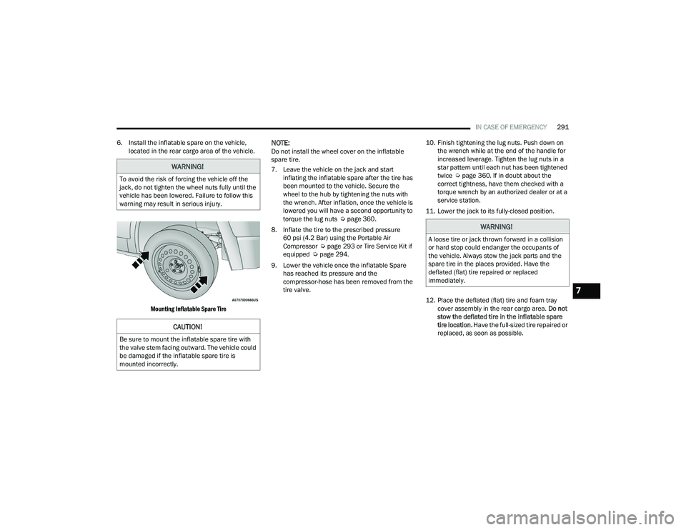
6. Install the inflatable spare on the vehicle, located in the rear cargo area of the vehicle.
Mounting Inflatable Spare Tire
NOTE:Do not install the wheel cover on the inflatable
spare tire.
7. Leave the vehicle on the jack and start inflating the inflatable spare after the tire has
been mounted to the vehicle. Secure the
wheel to the hub by tightening the nuts with
the wrench. After inflation, once the vehicle is
lowered you will have a second opportunity to
torque the lug nuts Ú page 360.
8. Inflate the tire to the prescribed pressure 60 psi (4.2 Bar) using the Portable Air
Compressor Ú page 293 or Tire Service Kit if
equipped Ú page 294.
9. Lower the vehicle once the inflatable Spare has reached its pressure and the
compressor-hose has been removed from the
tire valve. 10. Finish tightening the lug nuts. Push down on
the wrench while at the end of the handle for
increased leverage. Tighten the lug nuts in a
star pattern until each nut has been tightened
twice Ú page 360. If in doubt about the
correct tightness, have them checked with a
torque wrench by an authorized dealer or at a
service station.
11. Lower the jack to its fully-closed position.
12. Place the deflated (flat) tire and foam tray cover assembly in the rear cargo area. Do not
stow the deflated tire in the inflatable spare
tire location. Have the full-sized tire repaired or
replaced, as soon as possible.
WARNING!
To avoid the risk of forcing the vehicle off the
jack, do not tighten the wheel nuts fully until the
vehicle has been lowered. Failure to follow this
warning may result in serious injury.
CAUTION!
Be sure to mount the inflatable spare tire with
the valve stem facing outward. The vehicle could
be damaged if the inflatable spare tire is
mounted incorrectly.
WARNING!
A loose tire or jack thrown forward in a collision
or hard stop could endanger the occupants of
the vehicle. Always stow the jack parts and the
spare tire in the places provided. Have the
deflated (flat) tire repaired or replaced
immediately.
7
22_RUP_OM_EN_USC_t.book Page 291
Page 294 of 384
292IN CASE OF EMERGENCY
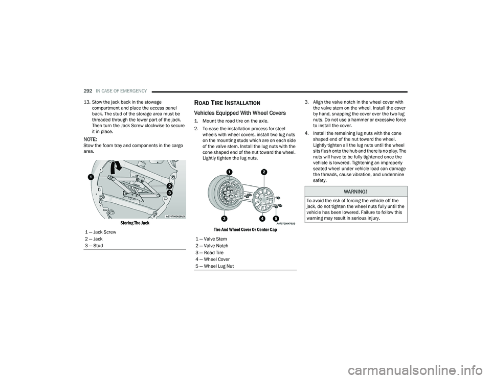
13. Stow the jack back in the stowage compartment and place the access panel
back. The stud of the storage area must be
threaded through the lower part of the jack.
Then turn the Jack Screw clockwise to secure
it in place.
NOTE:Stow the foam tray and components in the cargo
area.
Storing The Jack
ROAD TIRE INSTALLATION
Vehicles Equipped With Wheel Covers
1. Mount the road tire on the axle.
2. To ease the installation process for steel wheels with wheel covers, install two lug nuts
on the mounting studs which are on each side
of the valve stem. Install the lug nuts with the
cone shaped end of the nut toward the wheel.
Lightly tighten the lug nuts.
Tire And Wheel Cover Or Center Cap
3. Align the valve notch in the wheel cover with
the valve stem on the wheel. Install the cover
by hand, snapping the cover over the two lug
nuts. Do not use a hammer or excessive force
to install the cover.
4. Install the remaining lug nuts with the cone shaped end of the nut toward the wheel.
Lightly tighten all the lug nuts until the wheel
sits flush onto the hub and there is no play. The
nuts will have to be fully tightened once the
vehicle is lowered. Tightening an improperly
seated wheel under vehicle load can damage
the threads, cause vibration, and undermine
safety.
1 — Jack Screw
2 — Jack
3 — Stud
1 — Valve Stem
2 — Valve Notch
3 — Road Tire
4 — Wheel Cover
5 — Wheel Lug Nut
WARNING!
To avoid the risk of forcing the vehicle off the
jack, do not tighten the wheel nuts fully until the
vehicle has been lowered. Failure to follow this
warning may result in serious injury.
22_RUP_OM_EN_USC_t.book Page 292