ECU CHRYSLER PACIFICA HYBRID 2022 Workshop Manual
[x] Cancel search | Manufacturer: CHRYSLER, Model Year: 2022, Model line: PACIFICA HYBRID, Model: CHRYSLER PACIFICA HYBRID 2022Pages: 384, PDF Size: 23.92 MB
Page 296 of 384
294IN CASE OF EMERGENCY
8. After the tire reaches the
recommended pressure, lower the
vehicle with the jack as described in
the Jack Instructions section in this
manual.
9. Remove the speed limit label
sticker from the Portable Air
Compressor and place it on the
center of the steering wheel.
10. Return the Portable Air Compressor to the foam tray and secure it with the strap. Store
the foam tray in the cargo area.
RETURN INFLATABLE SPARE TIRE
To return Inflatable Spare Tire to its storage
location.
1. Return the Jack.
2. Deflate the spare tire. Use the Tire Service Kit or Portable Air Compressor and push the
deflation button to do this step. See the
Portable Air Compressor in this section for
additional information. The inflatable spare
tire will return to its original shape.
3. Install the inflatable spare tire back into its original stowage location and position facing
outward.
4. Install the foam tray with wrench and funnel installed.
5. Install and tighten the wing nut by hand.
6. Install the Tire Service Kit or Portable Air Compressor (if equipped) and tighten the
strap.
7. Install access panel door.
TIRE SERVICE KIT — IF EQUIPPED
Use this QR code to access your
digital experience.
Your vehicle may be equipped
with a Tire Service Kit. Small
punctures up to 1/4 inch (6 mm)
in the tire tread can be sealed with
Tire Service Kit. Foreign objects
(e.g., screws or nails) should not be removed from
the tire. Tire Service Kit can be used in outside
temperatures down to approximately -4°F (-20°C).
This kit will provide a temporary tire seal, allowing
you to drive your vehicle up to 100 miles (160 km)
with a maximum speed of 50 mph (80 km/h).
Tire Service Kit Storage
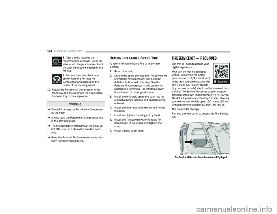
Remove the rear panel to access the Tire Service
Kit.
Tire Service Kit Access Panel Location — If Equipped
WARNING!
Do not lift or carry the Portable Air Compressor
by the hose.
Always stow the Portable Air Compressor only
in the provided place.
The metal end fitting from Power Plug may get
hot after use, so it should be handled care -
fully.
Keep the Portable Air Compressor away from
open flames or heat source.
22_RUP_OM_EN_USC_t.book Page 294
Page 297 of 384
IN CASE OF EMERGENCY295
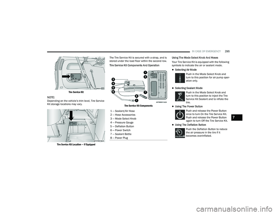
Tire Service Kit
NOTE:Depending on the vehicle’s trim level, Tire Service
Kit storage locations may vary.
Tire Service Kit Location — If Equipped
The Tire Service Kit is secured with a strap, and is
stored under the load floor within the second row.
Tire Service Kit Components And Operation
Tire Service Kit Components
Using The Mode Select Knob And Hoses
Your Tire Service Kit is equipped with the following
symbols to indicate the air or sealant mode.
Selecting Air Mode
Push in the Mode Select Knob and
turn to this position for air pump oper -
ation only.
Selecting Sealant Mode
Push in the Mode Select Knob and
turn to this position to inject the Tire
Service Kit Sealant and to inflate the
tire.
Using The Power Button
Push and release the Power Button
once to turn On the Tire Service Kit.
Push and release the Power Button
again to turn Off the Tire Service Kit.
Using The Deflation Button Push the Deflation Button to reduce
the air pressure in the tire if it
becomes overinflated.
1 — Sealant/Air Hose
2 — Hose Accessories
3 — Mode Select Knob
4 — Pressure Gauge
5 — Deflation Button
6 — Power Switch
7 — Sealant Bottle
8 — Power Plug
7
22_RUP_OM_EN_USC_t.book Page 295
Page 306 of 384
304IN CASE OF EMERGENCY
MANUAL PARK RELEASE
To move the vehicle in cases where the
transmission will not shift out of PARK (P) (such as
a depleted battery), a Manual Park Release is
available.
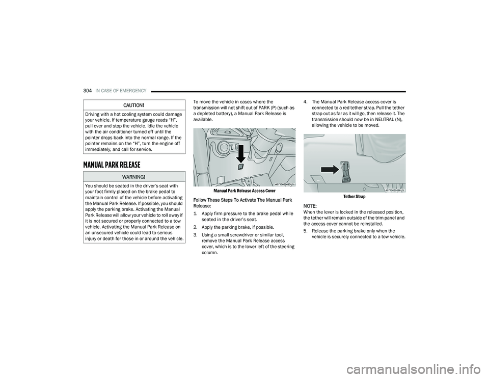
Manual Park Release Access Cover
Follow These Steps To Activate The Manual Park
Release:
1. Apply firm pressure to the brake pedal while seated in the driver’s seat.
2. Apply the parking brake, if possible.
3. Using a small screwdriver or similar tool, remove the Manual Park Release access
cover, which is to the lower left of the steering
column. 4. The Manual Park Release access cover is
connected to a red tether strap. Pull the tether
strap out as far as it will go, then release it. The
transmission should now be in NEUTRAL (N),
allowing the vehicle to be moved.
Tether Strap
NOTE:When the lever is locked in the released position,
the tether will remain outside of the trim panel and
the access cover cannot be reinstalled.
5. Release the parking brake only when the vehicle is securely connected to a tow vehicle.
CAUTION!
Driving with a hot cooling system could damage
your vehicle. If temperature gauge reads “H”,
pull over and stop the vehicle. Idle the vehicle
with the air conditioner turned off until the
pointer drops back into the normal range. If the
pointer remains on the “H”, turn the engine off
immediately, and call for service.
WARNING!
You should be seated in the driver’s seat with
your foot firmly placed on the brake pedal to
maintain control of the vehicle before activating
the Manual Park Release. If possible, you should
apply the parking brake. Activating the Manual
Park Release will allow your vehicle to roll away if
it is not secured or properly connected to a tow
vehicle. Activating the Manual Park Release on
an unsecured vehicle could lead to serious
injury or death for those in or around the vehicle.
22_RUP_OM_EN_USC_t.book Page 304
Page 309 of 384
IN CASE OF EMERGENCY307
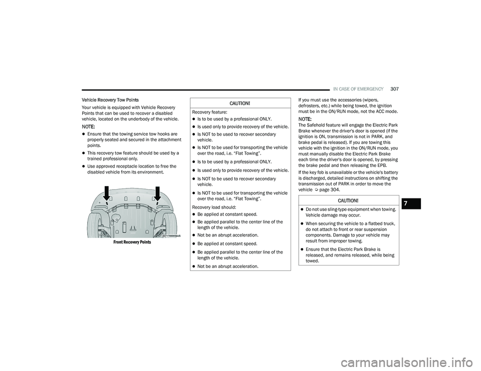
Vehicle Recovery Tow Points
Your vehicle is equipped with Vehicle Recovery
Points that can be used to recover a disabled
vehicle, located on the underbody of the vehicle.
NOTE:
Ensure that the towing service tow hooks are
properly seated and secured in the attachment
points.
This recovery tow feature should be used by a
trained professional only.
Use approved receptacle location to free the
disabled vehicle from its environment.
Front Recovery Points
If you must use the accessories (wipers,
defrosters, etc.) while being towed, the ignition
must be in the ON/RUN mode, not the ACC mode.
NOTE:The Safehold feature will engage the Electric Park
Brake whenever the driver's door is opened (if the
ignition is ON, transmission is not in PARK, and
brake pedal is released). If you are towing this
vehicle with the ignition in the ON/RUN mode, you
must manually disable the Electric Park Brake
each time the driver's door is opened, by pressing
the brake pedal and then releasing the EPB.
If the key fob is unavailable or the vehicle's battery
is discharged, detailed instructions on shifting the
transmission out of PARK in order to move the
vehicle Ú
page 304.
CAUTION!
Recovery feature:
Is to be used by a professional ONLY.
Is used only to provide recovery of the vehicle.
Is NOT to be used to recover secondary
vehicle.
Is NOT to be used for transporting the vehicle
over the road, i.e. “Flat Towing”.
Is to be used by a professional ONLY.
Is used only to provide recovery of the vehicle.
Is NOT to be used to recover secondary
vehicle.
Is NOT to be used for transporting the vehicle
over the road, i.e. “Flat Towing”.
Recovery load should:
Be applied at constant speed.
Be applied parallel to the center line of the
length of the vehicle.
Not be an abrupt acceleration.
Be applied at constant speed.
Be applied parallel to the center line of the
length of the vehicle.
Not be an abrupt acceleration.
CAUTION!
Do not use sling-type equipment when towing.
Vehicle damage may occur.
When securing the vehicle to a flatbed truck,
do not attach to front or rear suspension
components. Damage to your vehicle may
result from improper towing.
Ensure that the Electric Park Brake is
released, and remains released, while being
towed.
7
22_RUP_OM_EN_USC_t.book Page 307
Page 321 of 384
SERVICING AND MAINTENANCE319
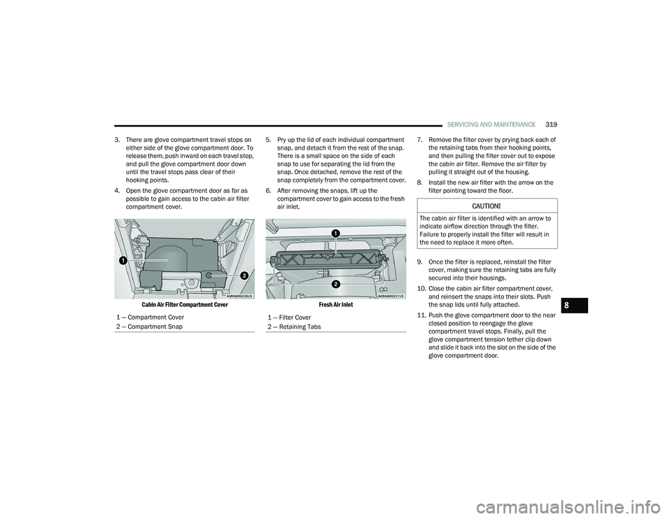
3. There are glove compartment travel stops on either side of the glove compartment door. To
release them, push inward on each travel stop,
and pull the glove compartment door down
until the travel stops pass clear of their
hooking points.
4. Open the glove compartment door as far as possible to gain access to the cabin air filter
compartment cover.
Cabin Air Filter Compartment Cover
5. Pry up the lid of each individual compartment
snap, and detach it from the rest of the snap.
There is a small space on the side of each
snap to use for separating the lid from the
snap. Once detached, remove the rest of the
snap completely from the compartment cover.
6. After removing the snaps, lift up the compartment cover to gain access to the fresh
air inlet.
Fresh Air Inlet
7. Remove the filter cover by prying back each of
the retaining tabs from their hooking points,
and then pulling the filter cover out to expose
the cabin air filter. Remove the air filter by
pulling it straight out of the housing.
8. Install the new air filter with the arrow on the filter pointing toward the floor.
9. Once the filter is replaced, reinstall the filter cover, making sure the retaining tabs are fully
secured into their housings.
10. Close the cabin air filter compartment cover, and reinsert the snaps into their slots. Push
the snap lids until fully attached.
11. Push the glove compartment door to the near closed position to reengage the glove
compartment travel stops. Finally, pull the
glove compartment tension tether clip down
and slide it back into the slot on the side of the
glove compartment door.
1 — Compartment Cover
2 — Compartment Snap
1 — Filter Cover
2 — Retaining Tabs
CAUTION!
The cabin air filter is identified with an arrow to
indicate airflow direction through the filter.
Failure to properly install the filter will result in
the need to replace it more often.
8
22_RUP_OM_EN_USC_t.book Page 319
Page 329 of 384
SERVICING AND MAINTENANCE327
(Continued)
Make sure that the coolant expansion bottle
overflow hoses are not kinked or obstructed.
Keep the front of the radiator clean. If your
vehicle is equipped with air conditioning, keep
the front of the condenser clean.
Do not change the thermostat for Summer or
Winter operation. If replacement is ever neces -
sary, install ONLY the correct type thermostat.
Other designs may result in unsatisfactory
engine cooling performance, poor gas mileage,
and increased emissions.
BRAKE SYSTEM
In order to ensure brake system performance, all
brake system components should be inspected
periodically. For the proper maintenance intervals
Ú page 310.
Brake Master Cylinder
The fluid in the master cylinder should be checked
when performing under hood services or
immediately if the Brake Warning Light is
illuminated.
Be sure to clean the top of the master cylinder area
before removing the cap. If necessary, add fluid to
bring the fluid level up to the requirements
described on the brake fluid reservoir. With disc
brakes, fluid level can be expected to fall as the
brake pads wear. Brake fluid level should be
checked when pads are replaced. However, low
fluid level may be caused by a leak and a checkup
may be needed.
Use only manufacturer recommended brake fluid
Úpage 366.
WARNING!
Riding the brakes can lead to brake failure and
possibly a collision. Driving with your foot resting
or riding on the brake pedal can result in
abnormally high brake temperatures, excessive
lining wear, and possible brake damage. You
would not have your full braking capacity in an
emergency.
WARNING!
Use only manufacturer recommended brake
fluid Ú page 366. Using the wrong type of
brake fluid can severely damage your brake
system and/or impair its performance. The
proper type of brake fluid for your vehicle is
also identified on the original factory installed
hydraulic master cylinder reservoir.
To avoid contamination from foreign matter or
moisture, use only new brake fluid or fluid that
has been in a tightly closed container. Keep
the master cylinder reservoir cap secured at
all times. Brake fluid in an open container
absorbs moisture from the air resulting in a
lower boiling point. This may cause it to boil
unexpectedly during hard or prolonged
braking, resulting in sudden brake failure. This
could result in a collision.
Overfilling the brake fluid reservoir can result
in spilling brake fluid on hot engine parts,
causing the brake fluid to catch fire. Brake
fluid can also damage painted and vinyl
surfaces, care should be taken to avoid its
contact with these surfaces.
Do not allow petroleum-based fluid to contam -
inate the brake fluid. Brake seal components
could be damaged, causing partial or
complete brake failure. This could result in a
collision.
WARNING!
8
22_RUP_OM_EN_USC_t.book Page 327
Page 331 of 384

SERVICING AND MAINTENANCE329
FUSES
General Information
The fuses protect electrical systems against
excessive current. When a device does not work, you must check the
fuse element inside the blade fuse for a break/
melt.
Also, please be aware that using power outlets for
extended periods of time with the engine off may
result in vehicle battery discharge.
Blade Fuses
Underhood Fuses
The Power Distribution Center (PDC) is located in
the engine compartment near the battery. This
center contains cartridge fuses, mini-fuses,
micro-fuses, circuit breakers and relays. A label
that identifies each component is printed on the
inside of the cover.
Before any procedure is done on the PDC, make
sure engine is turned off.
Remove the cover by unlatching the two locks
located at each side of the PDC cover, avoid using
screwdrivers or any other tool to remove the cover,
since they may apply excessive force and result in
a broken/damaged part.
After service is done, secure the cover with its two
locks.
NOTE:The function and amperage of the following fuses
are different, depending on vehicle trim level and
content.
WARNING!
When replacing a blown fuse, always use an
appropriate replacement fuse with the same
amp rating as the original fuse. Never replace
a fuse with another fuse of higher amp rating.
Never replace a blown fuse with metal wires or
any other material. Do not place a fuse inside
a circuit breaker cavity or vice versa. Failure to
use proper fuses may result in serious
personal injury, fire and/or property damage.
Before replacing a fuse, make sure that the
ignition is off and that all the other services
are switched off and/or disengaged.
If the replaced fuse blows again, contact an
authorized dealer.
If a general protection fuse for safety systems
(air bag system, braking system), power unit
systems (engine system, transmission
system) or steering system blows, contact an
authorized dealer.
1 — Fuse Element
2 — Blade Fuse with a good/functional fuse
element
3 — Blade fuse with a bad/not functional fuse
element (blown fuse)CAUTION!
When installing the power distribution center
cover, it is important to ensure the cover is
properly positioned and fully latched. Failure to
do so may allow water to get into the power
distribution center and possibly result in an
electrical system failure.8
22_RUP_OM_EN_USC_t.book Page 329
Page 335 of 384
SERVICING AND MAINTENANCE333
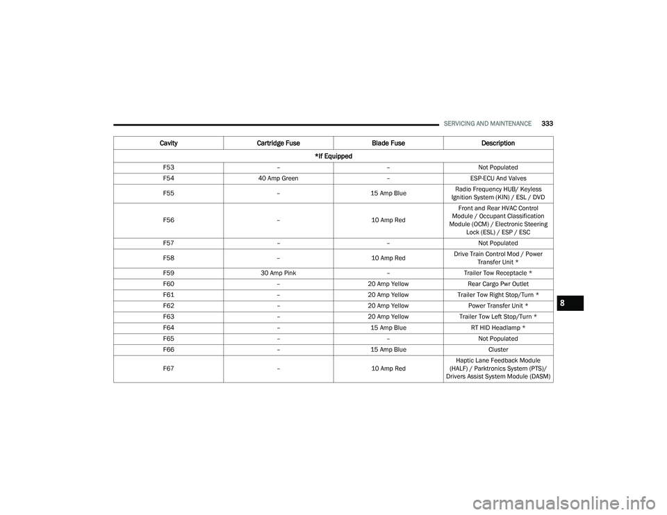
F53 ––Not Populated
F54 40 Amp Green –ESP-ECU And Valves
F55 –15 Amp BlueRadio Frequency HUB/ Keyless
Ignition System (KIN) / ESL / DVD
F56 –10 Amp RedFront and Rear HVAC Control
Module / Occupant Classification
Module (OCM) / Electronic Steering Lock (ESL) / ESP / ESC
F57 ––Not Populated
F58 –10 Amp RedDrive Train Control Mod / Power
Transfer Unit *
F59 30 Amp Pink –Trailer Tow Receptacle *
F60 –20 Amp Yellow Rear Cargo Pwr Outlet
F61 –20 Amp YellowTrailer Tow Right Stop/Turn *
F62 –20 Amp Yellow Power Transfer Unit *
F63 –20 Amp Yellow Trailer Tow Left Stop/Turn *
F64 –15 Amp Blue RT HID Headlamp *
F65 ––Not Populated
F66 –15 Amp Blue Cluster
F67 –10 Amp RedHaptic Lane Feedback Module
(HALF) / Parktronics System (PTS)/
Drivers Assist System Module (DASM)
Cavity Cartridge Fuse Blade FuseDescription
*If Equipped
8
22_RUP_OM_EN_USC_t.book Page 333
Page 337 of 384
SERVICING AND MAINTENANCE335
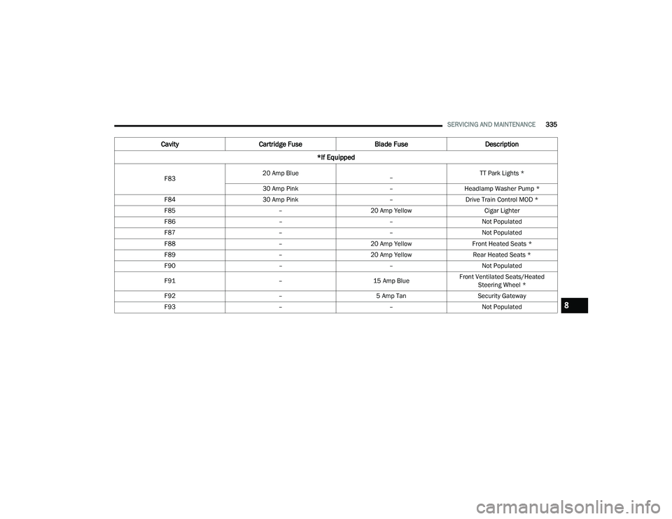
F83 20 Amp Blue
– TT Park Lights *
30 Amp Pink –Headlamp Washer Pump *
F84 30 Amp Pink –Drive Train Control MOD *
F85 –20 Amp Yellow Cigar Lighter
F86 ––Not Populated
F87 ––Not Populated
F88 –20 Amp Yellow Front Heated Seats *
F89 –20 Amp Yellow Rear Heated Seats *
F90 ––Not Populated
F91 –15 Amp BlueFront Ventilated Seats/Heated
Steering Wheel *
F92 –5 Amp Tan Security Gateway
F93 ––Not Populated
CavityCartridge Fuse Blade FuseDescription
*If Equipped
8
22_RUP_OM_EN_USC_t.book Page 335
Page 373 of 384
371
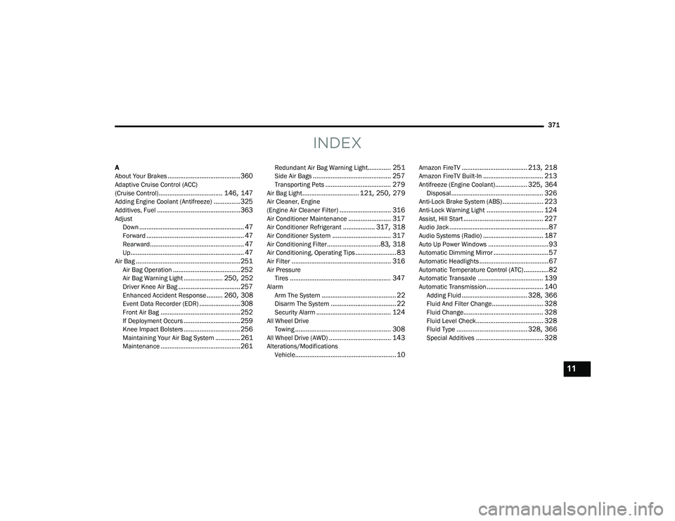
INDEX
A
About Your Brakes......................................... 360Adaptive Cruise Control (ACC)
(Cruise Control).................................... 146, 147Adding Engine Coolant (Antifreeze)............... 325Additives, Fuel............................................... 363AdjustDown........................................................... 47Forward....................................................... 47Rearward..................................................... 47Up................................................................ 47Air Bag........................................................... 251Air Bag Operation...................................... 252Air Bag Warning Light...................... 250, 252Driver Knee Air Bag................................... 257Enhanced Accident Response......... 260, 308Event Data Recorder (EDR)....................... 308Front Air Bag............................................. 252If Deployment Occurs................................ 259Knee Impact Bolsters................................ 256Maintaining Your Air Bag System.............. 261Maintenance............................................. 261
Redundant Air Bag Warning Light............. 251Side Air Bags............................................ 257Transporting Pets..................................... 279Air Bag Light................................ 121, 250, 279Air Cleaner, Engine
(Engine Air Cleaner Filter)............................. 316Air Conditioner Maintenance........................ 317Air Conditioner Refrigerant.................. 317, 318Air Conditioner System................................. 317Air Conditioning Filter..............................83, 318Air Conditioning, Operating Tips....................... 83Air Filter........................................................ 316Air PressureTires......................................................... 347AlarmArm The System.......................................... 22Disarm The System..................................... 22Security Alarm.......................................... 124All Wheel DriveTowing...................................................... 308All Wheel Drive (AWD)................................... 143Alterations/ModificationsVehicle......................................................... 10
Amazon FireTV..................................... 213, 218Amazon FireTV Built-In.................................. 213Antifreeze (Engine Coolant).................. 325, 364Disposal.................................................... 326Anti-Lock Brake System (ABS)....................... 223Anti-Lock Warning Light................................ 124Assist, Hill Start............................................. 227Audio Jack........................................................87Audio Systems (Radio).................................. 187Auto Up Power Windows..................................93Automatic Dimming Mirror...............................57Automatic Headlights.......................................67Automatic Temperature Control (ATC)..............82Automatic Transaxle..................................... 139Automatic Transmission................................ 140Adding Fluid..................................... 328, 366Fluid And Filter Change............................. 328Fluid Change............................................. 328Fluid Level Check...................................... 328Fluid Type........................................ 328, 366Special Additives...................................... 328
11
22_RUP_OM_EN_USC_t.book Page 371