CHRYSLER SEBRING COUPE 2004 2.G Owners Manual
SEBRING COUPE 2004 2.G
CHRYSLER
CHRYSLER
https://www.carmanualsonline.info/img/25/8545/w960_8545-0.png
CHRYSLER SEBRING COUPE 2004 2.G Owners Manual
Trending: buttons, trunk, high beam, spark plugs replace, sensor, maintenance schedule, power steering fluid
Page 281 of 382
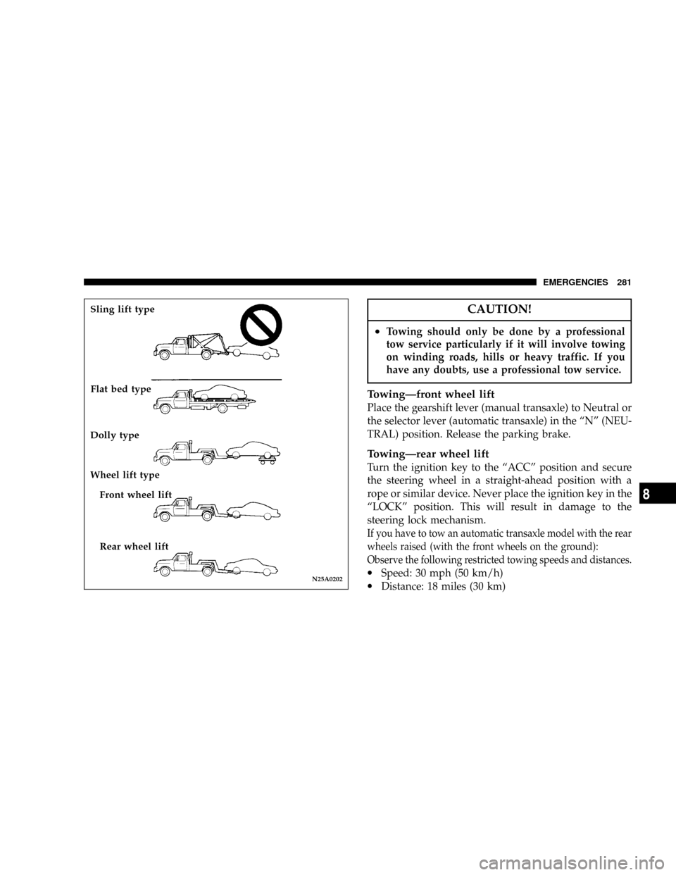
CAUTION!
²Towing should only be done by a professional
tow service particularly if it will involve towing
on winding roads, hills or heavy traffic. If you
have any doubts, use a professional tow service.
TowingÐfront wheel lift
Place the gearshift lever (manual transaxle) to Neutral or
the selector lever (automatic transaxle) in the ªNº (NEU-
TRAL) position. Release the parking brake.
TowingÐrear wheel lift
Turn the ignition key to the ªACCº position and secure
the steering wheel in a straight-ahead position with a
rope or similar device. Never place the ignition key in the
ªLOCKº position. This will result in damage to the
steering lock mechanism.
If you have to tow an automatic transaxle model with the rear
wheels raised (with the front wheels on the ground):
Observe the following restricted towing speeds and distances.
·Speed: 30 mph (50 km/h)
·Distance: 18 miles (30 km)N25A0202
Sling lift type
Flat bed type
Dolly type
Wheel lift type
Front wheel lift
Rear wheel lift
EMERGENCIES 281
8
Page 282 of 382
CAUTION!
Never tow an automatic transaxle model with the
rear wheels raised (with the front wheels on the
ground) when the automatic transaxle fluid level is
low. This may cause serious and expensive damage
to the transaxle.
FUSESFuse block
To prevent damage to the electrical system due to short-
circuiting or overloading, each individual circuit is pro-
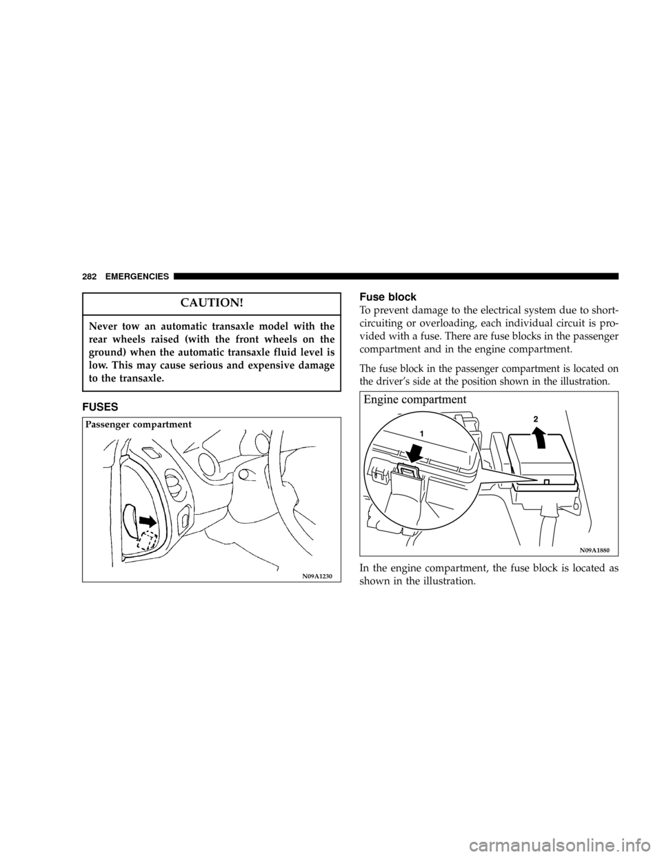
vided with a fuse. There are fuse blocks in the passenger
compartment and in the engine compartment.
The fuse block in the passenger compartment is located on
the driver's side at the position shown in the illustration.
In the engine compartment, the fuse block is located as
shown in the illustration.N09A1230
Passenger compartment
N09A1880
282 EMERGENCIES
Page 283 of 382
FUSIBLE LINKS
Fusible links will melt to prevent a fire in the event that
a large current flows through a system protected by a
fusible link. In case of a melted fusible link, see your
authorized dealer for inspection and replacement.
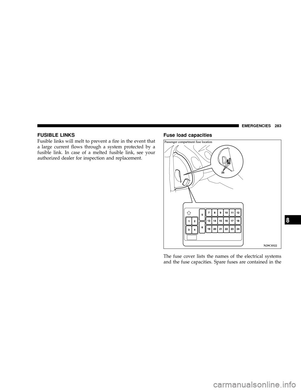
Fuse load capacities
The fuse cover lists the names of the electrical systems
and the fuse capacities. Spare fuses are contained in the
N29C0322
EMERGENCIES 283
8
Page 284 of 382
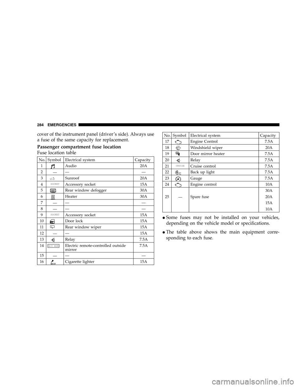
cover of the instrument panel (driver 's side). Always use
a fuse of the same capacity for replacement.
Passenger compartment fuse location
Fuse location table
No. Symbol Electrical system Capacity
1
Audio 20A
2
ÐÐÐ
3
Sunroof 20A
4
SOCKETAccessory socket 15A
5
Rear window defogger 30A
6
Heater 30A
7
ÐÐÐ
8
ÐÐÐ
9
SOCKETAccessory socket 15A
10
Door lock 15A
11
Rear window wiper 15A
12
ÐÐ 15A
13
Relay 7.5A
14
R/C MIRElectric remote-controlled outside
mirror7.5A
15
ÐÐÐ
16
Cigarette lighter 15A
No. Symbol Electrical system Capacity
17
Engine Control 7.5A
18
Windshield wiper 20A
19
Door mirror heater 7.5A
20
Relay 7.5A
21
CRUISECruise control 7.5A
22
Back up light 7.5A
23
Gauge 7.5A
24
Engine control 10A
30A
25
ÐSpare fuse 20A
15A
10A
ISome fuses may not be installed on your vehicles,
depending on the vehicle model or specifications.
IThe table above shows the main equipment corre-
sponding to each fuse.
284 EMERGENCIES
Page 285 of 382
Spare fuse location
Spare fuses are contained in the cover of the instru-
ment panel (driver 's side). Always use a fuse of the
same capacity for replacement.
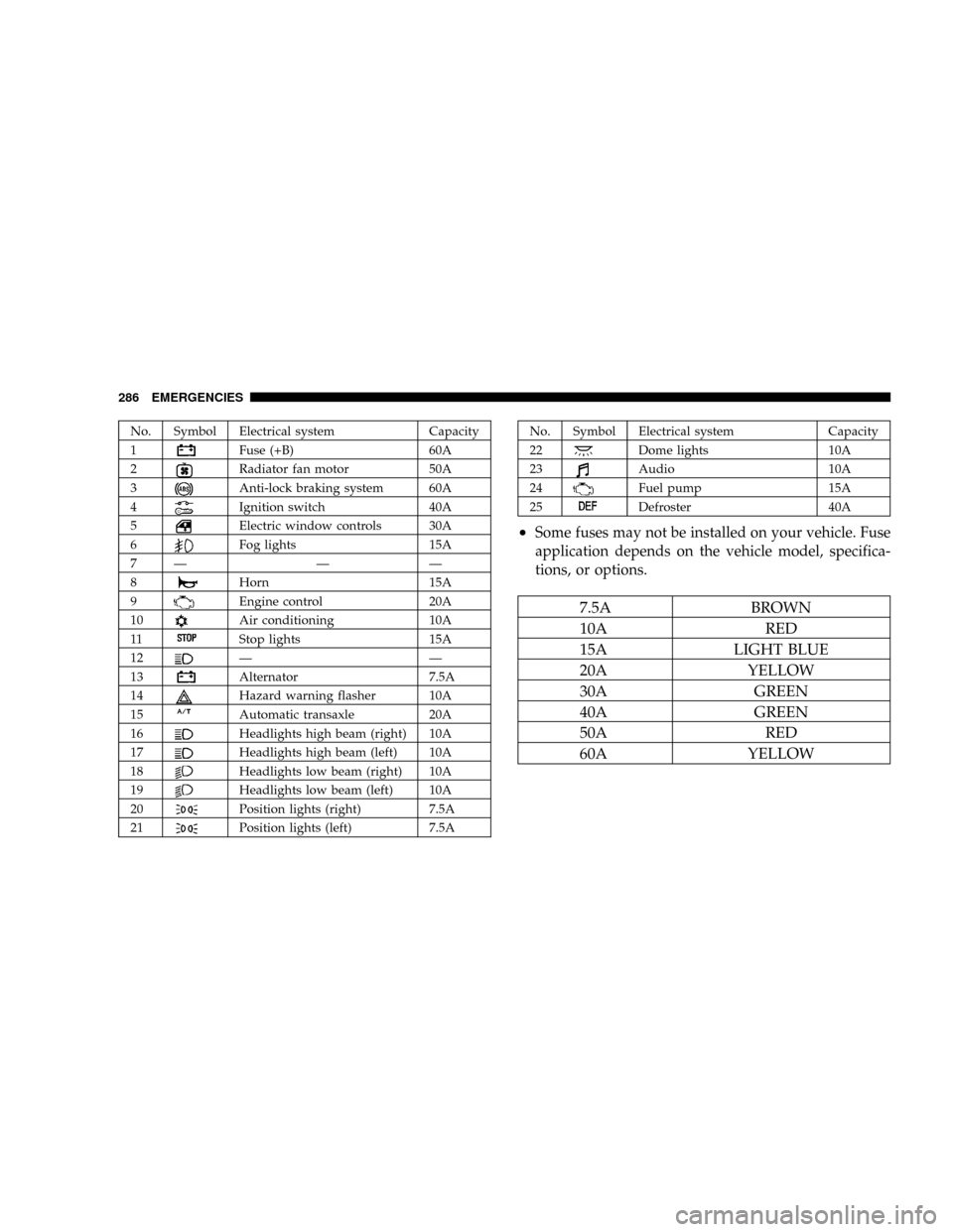
Engine compartment Fuse location table
N29B2642
Engine compartment fuse location
EMERGENCIES 285
8
Page 286 of 382
No. Symbol Electrical system Capacity
1
Fuse (+B) 60A
2
Radiator fan motor 50A
3
Anti-lock braking system 60A
4
Ignition switch 40A
5
Electric window controls 30A
6
Fog lights 15A
7Ð Ð Ð
8
Horn 15A
9
Engine control 20A
10
Air conditioning 10A
11
Stop lights 15A
12
ÐÐ
13
Alternator 7.5A
14
Hazard warning flasher 10A
15
Automatic transaxle 20A
16
Headlights high beam (right) 10A
17
Headlights high beam (left) 10A
18
Headlights low beam (right) 10A
19
Headlights low beam (left) 10A
20
Position lights (right) 7.5A
21
Position lights (left) 7.5A
No. Symbol Electrical system Capacity
22
Dome lights 10A
23
Audio 10A
24
Fuel pump 15A
25
Defroster 40A
²Some fuses may not be installed on your vehicle. Fuse
application depends on the vehicle model, specifica-
tions, or options.
7.5A BROWN
10A RED
15A LIGHT BLUE
20A YELLOW
30A GREEN
40A GREEN
50A RED
60A YELLOW
286 EMERGENCIES
Page 287 of 382
Fuse replacement
1. Before replacing a fuse, always turn off the electrical
item concerned and turn the ignition key to the ªLOCKº
position.
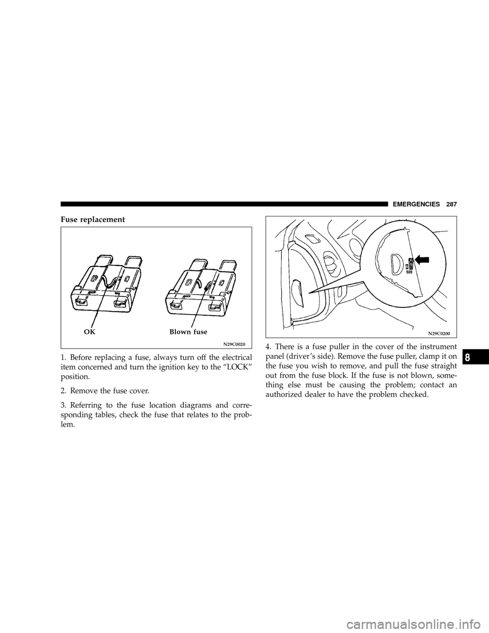
2. Remove the fuse cover.
3. Referring to the fuse location diagrams and corre-
sponding tables, check the fuse that relates to the prob-
lem.4. There is a fuse puller in the cover of the instrument
panel (driver 's side). Remove the fuse puller, clamp it on
the fuse you wish to remove, and pull the fuse straight
out from the fuse block. If the fuse is not blown, some-
thing else must be causing the problem; contact an
authorized dealer to have the problem checked.
N29C0020
OK Blown fuseN29C0200
EMERGENCIES 287
8
Page 288 of 382
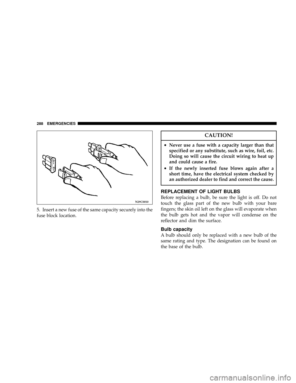
5. Insert a new fuse of the same capacity securely into the
fuse block location.
CAUTION!
²Never use a fuse with a capacity larger than that
specified or any substitute, such as wire, foil, etc.
Doing so will cause the circuit wiring to heat up
and could cause a fire.
²If the newly inserted fuse blows again after a
short time, have the electrical system checked by
an authorized dealer to find and correct the cause.
REPLACEMENT OF LIGHT BULBS
Before replacing a bulb, be sure the light is off. Do not
touch the glass part of the new bulb with your bare
fingers; the skin oil left on the glass will evaporate when
the bulb gets hot and the vapor will condense on the
reflector and dim the surface.
Bulb capacity
A bulb should only be replaced with a new bulb of the
same rating and type. The designation can be found on
the base of the bulb.
N29C0010
288 EMERGENCIES
Page 289 of 382
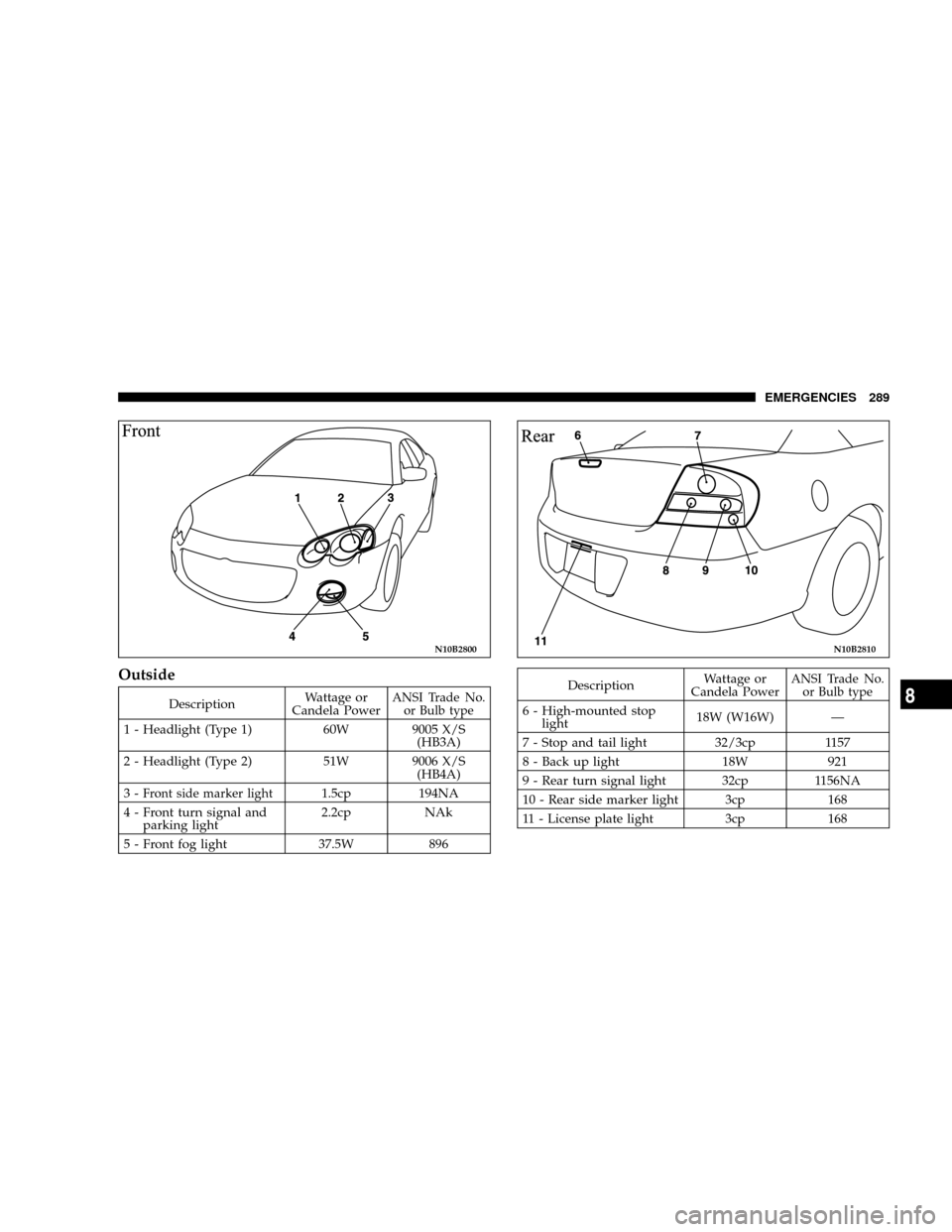
Outside
DescriptionWattage or
Candela PowerANSI Trade No.
or Bulb type
1 - Headlight (Type 1) 60W 9005 X/S
(HB3A)
2 - Headlight (Type 2) 51W 9006 X/S
(HB4A)
3-
Front side marker light1.5cp 194NA
4 - Front turn signal and
parking light2.2cp NAk
5 - Front fog light 37.5W 896
DescriptionWattage or
Candela PowerANSI Trade No.
or Bulb type
6 - High-mounted stop
light18W (W16W) Ð
7 - Stop and tail light 32/3cp 1157
8 - Back up light 18W 921
9 - Rear turn signal light 32cp 1156NA
10 - Rear side marker light 3cp 168
11 - License plate light 3cp 168
N10B2800N10B2810
EMERGENCIES 289
8
Page 290 of 382
Inside
DescriptionWattage or
Candela Power
Dome Light 10W
Rear personal light 8W
Trunk light 5W
Reading light 4W
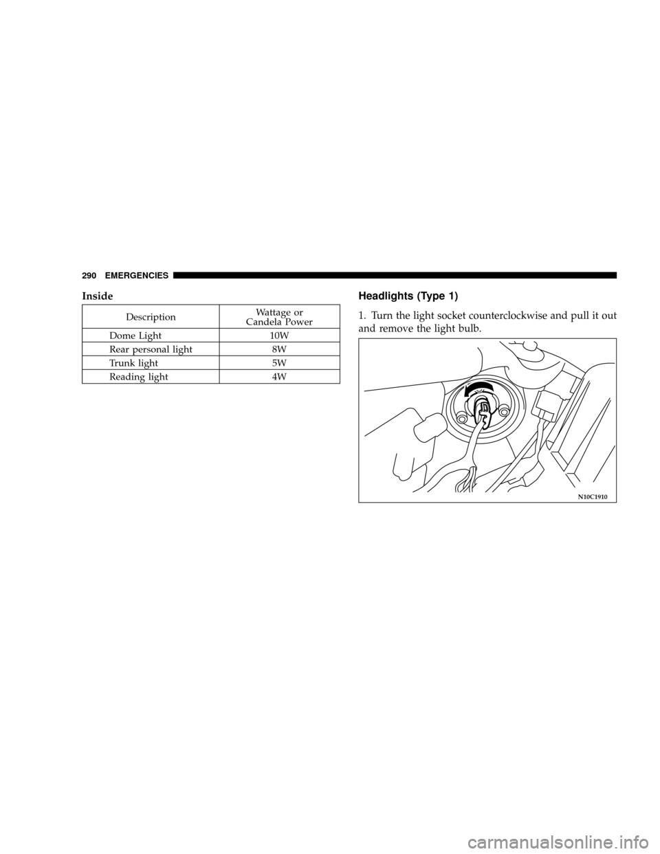
Headlights (Type 1)
1. Turn the light socket counterclockwise and pull it out
and remove the light bulb.
N10C1910
290 EMERGENCIES
Trending: oil type, climate control, service schedule, dead battery, low beam, child seat, seat memory

