relay CHRYSLER TOWN AND COUNTRY 2002 Service Manual
[x] Cancel search | Manufacturer: CHRYSLER, Model Year: 2002, Model line: TOWN AND COUNTRY, Model: CHRYSLER TOWN AND COUNTRY 2002Pages: 2399, PDF Size: 57.96 MB
Page 263 of 2399
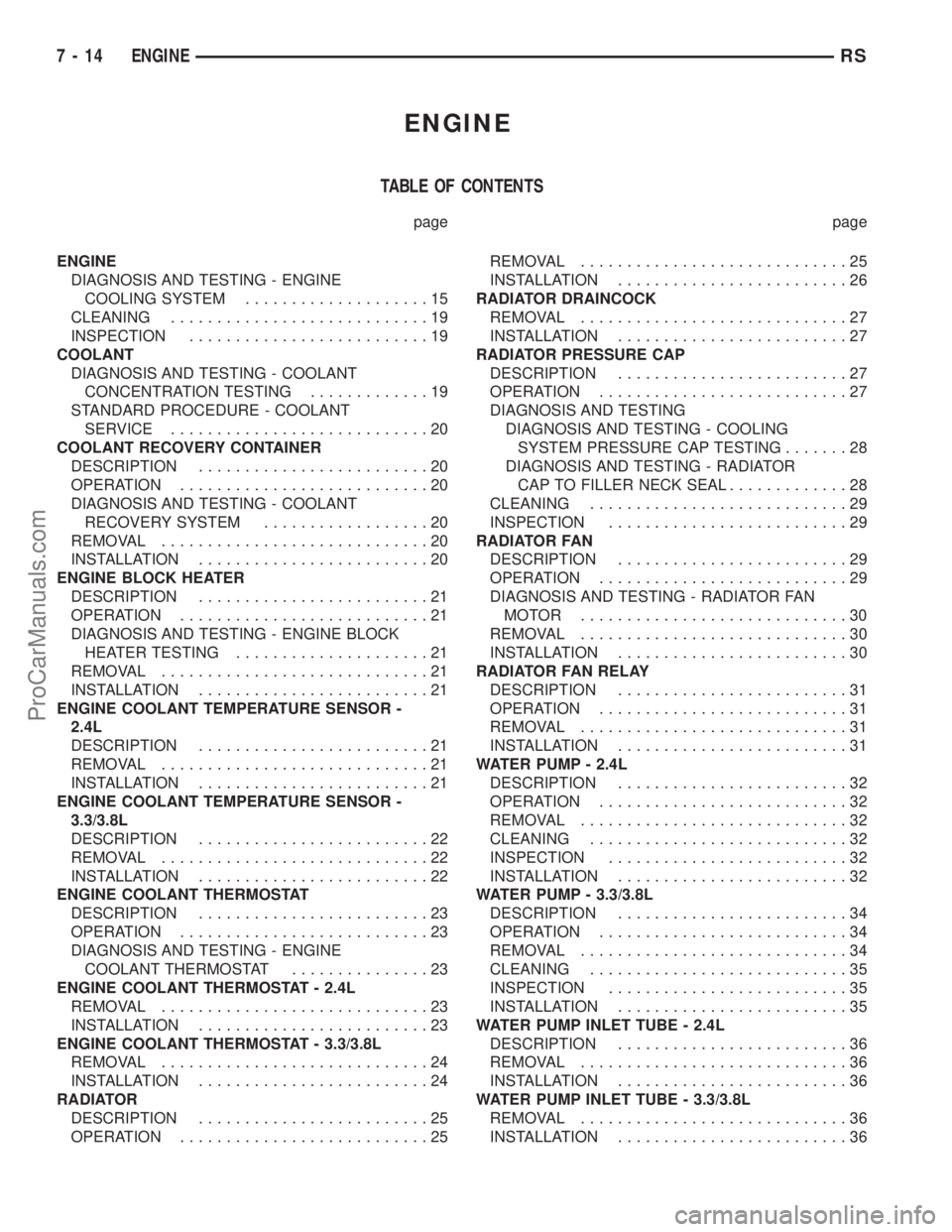
ENGINE
TABLE OF CONTENTS
page page
ENGINE
DIAGNOSIS AND TESTING - ENGINE
COOLING SYSTEM....................15
CLEANING............................19
INSPECTION..........................19
COOLANT
DIAGNOSIS AND TESTING - COOLANT
CONCENTRATION TESTING.............19
STANDARD PROCEDURE - COOLANT
SERVICE............................20
COOLANT RECOVERY CONTAINER
DESCRIPTION.........................20
OPERATION...........................20
DIAGNOSIS AND TESTING - COOLANT
RECOVERY SYSTEM..................20
REMOVAL.............................20
INSTALLATION.........................20
ENGINE BLOCK HEATER
DESCRIPTION.........................21
OPERATION...........................21
DIAGNOSIS AND TESTING - ENGINE BLOCK
HEATER TESTING.....................21
REMOVAL.............................21
INSTALLATION.........................21
ENGINE COOLANT TEMPERATURE SENSOR -
2.4L
DESCRIPTION.........................21
REMOVAL.............................21
INSTALLATION.........................21
ENGINE COOLANT TEMPERATURE SENSOR -
3.3/3.8L
DESCRIPTION.........................22
REMOVAL.............................22
INSTALLATION.........................22
ENGINE COOLANT THERMOSTAT
DESCRIPTION.........................23
OPERATION...........................23
DIAGNOSIS AND TESTING - ENGINE
COOLANT THERMOSTAT...............23
ENGINE COOLANT THERMOSTAT - 2.4L
REMOVAL.............................23
INSTALLATION.........................23
ENGINE COOLANT THERMOSTAT - 3.3/3.8L
REMOVAL.............................24
INSTALLATION.........................24
RADIATOR
DESCRIPTION.........................25
OPERATION...........................25REMOVAL.............................25
INSTALLATION.........................26
RADIATOR DRAINCOCK
REMOVAL.............................27
INSTALLATION.........................27
RADIATOR PRESSURE CAP
DESCRIPTION.........................27
OPERATION...........................27
DIAGNOSIS AND TESTING
DIAGNOSIS AND TESTING - COOLING
SYSTEM PRESSURE CAP TESTING.......28
DIAGNOSIS AND TESTING - RADIATOR
CAP TO FILLER NECK SEAL.............28
CLEANING............................29
INSPECTION..........................29
RADIATOR FAN
DESCRIPTION.........................29
OPERATION...........................29
DIAGNOSIS AND TESTING - RADIATOR FAN
MOTOR .............................30
REMOVAL.............................30
INSTALLATION.........................30
RADIATOR FAN RELAY
DESCRIPTION.........................31
OPERATION...........................31
REMOVAL.............................31
INSTALLATION.........................31
WATER PUMP - 2.4L
DESCRIPTION.........................32
OPERATION...........................32
REMOVAL.............................32
CLEANING............................32
INSPECTION..........................32
INSTALLATION.........................32
WATER PUMP - 3.3/3.8L
DESCRIPTION.........................34
OPERATION...........................34
REMOVAL.............................34
CLEANING............................35
INSPECTION..........................35
INSTALLATION.........................35
WATER PUMP INLET TUBE - 2.4L
DESCRIPTION.........................36
REMOVAL.............................36
INSTALLATION.........................36
WATER PUMP INLET TUBE - 3.3/3.8L
REMOVAL.............................36
INSTALLATION.........................36
7 - 14 ENGINERS
ProCarManuals.com
Page 279 of 2399
DIAGNOSIS AND TESTING - RADIATOR FAN
MOTOR
RADIATOR FAN DIAGNOSIS CHART
CONDITION POSSIBLE CAUSES CORRECTION
NOISY RADIATOR FAN 1. Fan blade loose. 1. Replace fan assembly. (Refer to
7 - COOLING/ENGINE/RADIATOR
FAN - REMOVAL)
2. Fan blade striking a surrounding
object.2. Locate point of fan blade contact
and repair as necessary.
3. Air obstructions at radiator or A/C
condenser.3. Remove obstructions and/or
clean debris.
4. Electric fan motor defective. 4. Replace fan assembly. (Refer to
7 - COOLING/ENGINE/RADIATOR
FAN - REMOVAL)
ELECTRIC FAN MOTOR DOES
NOT OPERATE1. Fan relay, powertrain control
module (PCM), coolant temperature
sensor, or wiring defective.1. (Refer to Appropriate Diagnostic
Information) Repair as necessary.
2. Defective A/C pressure
transducer.2. (Refer to Appropriate Diagnostic
Information) Repair as necessary.
ELECTRIC RADIATOR FAN
OPERATES ALL THE TIME1. Fan relay, powertrain control
module (PCM), coolant temperature
sensor or wiring defective.1. (Refer to Appropriate Diagnostic
Information) Repair as necessary.
2. Check for low coolant level. 2. Add coolant as necessary.
3. Defective A/C pressure
transducer.3. (Refer to Appropriate Diagnostic
Information) Repair as necessary.
REMOVAL
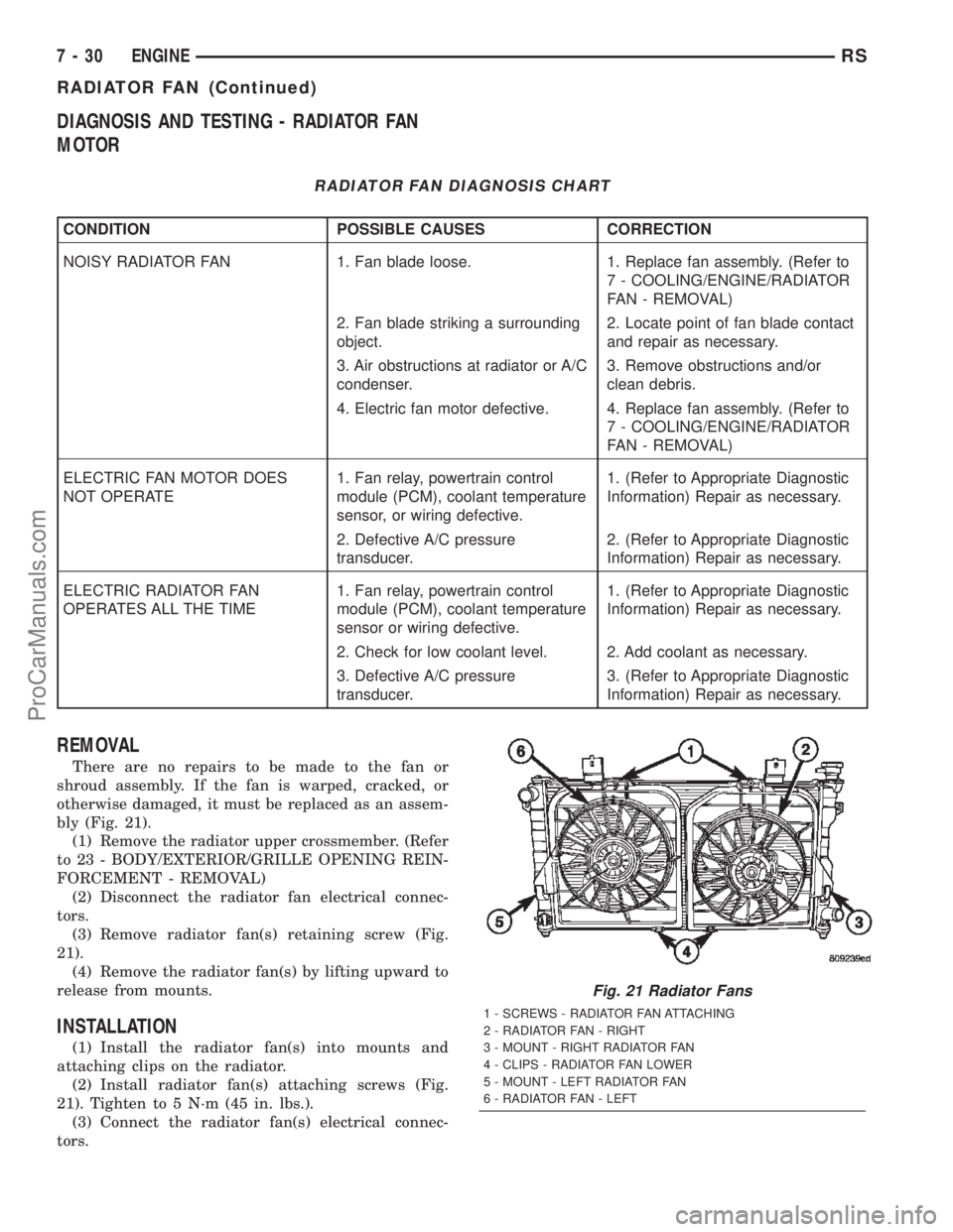
There are no repairs to be made to the fan or
shroud assembly. If the fan is warped, cracked, or
otherwise damaged, it must be replaced as an assem-
bly (Fig. 21).
(1) Remove the radiator upper crossmember. (Refer
to 23 - BODY/EXTERIOR/GRILLE OPENING REIN-
FORCEMENT - REMOVAL)
(2) Disconnect the radiator fan electrical connec-
tors.
(3) Remove radiator fan(s) retaining screw (Fig.
21).
(4) Remove the radiator fan(s) by lifting upward to
release from mounts.
INSTALLATION
(1) Install the radiator fan(s) into mounts and
attaching clips on the radiator.
(2) Install radiator fan(s) attaching screws (Fig.
21). Tighten to 5 N´m (45 in. lbs.).
(3) Connect the radiator fan(s) electrical connec-
tors.
Fig. 21 Radiator Fans
1 - SCREWS - RADIATOR FAN ATTACHING
2 - RADIATOR FAN - RIGHT
3 - MOUNT - RIGHT RADIATOR FAN
4 - CLIPS - RADIATOR FAN LOWER
5 - MOUNT - LEFT RADIATOR FAN
6 - RADIATOR FAN - LEFT
7 - 30 ENGINERS
RADIATOR FAN (Continued)
ProCarManuals.com
Page 280 of 2399
(4) Install the radiator upper support crossmem-
ber. (Refer to 23 - BODY/EXTERIOR/GRILLE OPEN-
ING REINFORCEMENT - INSTALLATION)
(5) Install the upper radiator mounts to the cross-
member bolts, if removed. Tighten to 8 N´m (70 in.
lbs.).
(6) Install the radiator upper hose to the support
clip (2.4L engine).
RADIATOR FAN RELAY
DESCRIPTION
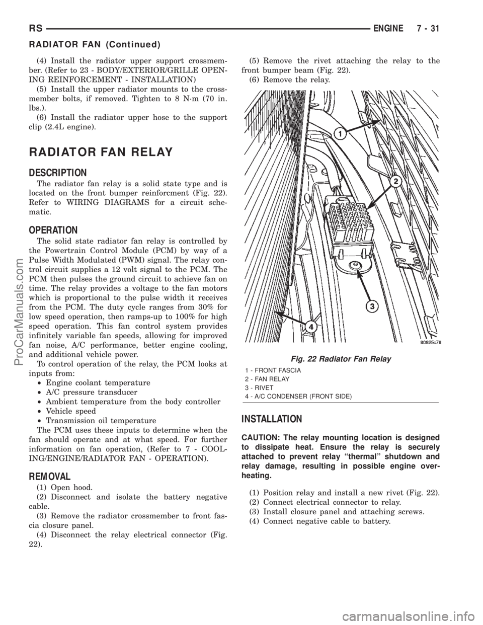
The radiator fan relay is a solid state type and is
located on the front bumper reinforcment (Fig. 22).
Refer to WIRING DIAGRAMS for a circuit sche-
matic.
OPERATION
The solid state radiator fan relay is controlled by
the Powertrain Control Module (PCM) by way of a
Pulse Width Modulated (PWM) signal. The relay con-
trol circuit supplies a 12 volt signal to the PCM. The
PCM then pulses the ground circuit to achieve fan on
time. The relay provides a voltage to the fan motors
which is proportional to the pulse width it receives
from the PCM. The duty cycle ranges from 30% for
low speed operation, then ramps-up to 100% for high
speed operation. This fan control system provides
infinitely variable fan speeds, allowing for improved
fan noise, A/C performance, better engine cooling,
and additional vehicle power.
To control operation of the relay, the PCM looks at
inputs from:
²Engine coolant temperature
²A/C pressure transducer
²Ambient temperature from the body controller
²Vehicle speed
²Transmission oil temperature
The PCM uses these inputs to determine when the
fan should operate and at what speed. For further
information on fan operation, (Refer to 7 - COOL-
ING/ENGINE/RADIATOR FAN - OPERATION).
REMOVAL
(1) Open hood.
(2) Disconnect and isolate the battery negative
cable.
(3) Remove the radiator crossmember to front fas-
cia closure panel.
(4) Disconnect the relay electrical connector (Fig.
22).(5) Remove the rivet attaching the relay to the
front bumper beam (Fig. 22).
(6) Remove the relay.
INSTALLATION
CAUTION: The relay mounting location is designed
to dissipate heat. Ensure the relay is securely
attached to prevent relay ªthermalº shutdown and
relay damage, resulting in possible engine over-
heating.
(1) Position relay and install a new rivet (Fig. 22).
(2) Connect electrical connector to relay.
(3) Install closure panel and attaching screws.
(4) Connect negative cable to battery.
Fig. 22 Radiator Fan Relay
1 - FRONT FASCIA
2 - FAN RELAY
3 - RIVET
4 - A/C CONDENSER (FRONT SIDE)
RSENGINE7-31
RADIATOR FAN (Continued)
ProCarManuals.com
Page 303 of 2399
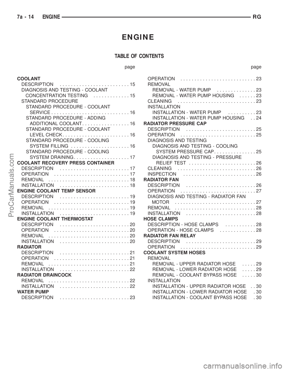
ENGINE
TABLE OF CONTENTS
page page
COOLANT
DESCRIPTION.........................15
DIAGNOSIS AND TESTING - COOLANT
CONCENTRATION TESTING.............15
STANDARD PROCEDURE
STANDARD PROCEDURE - COOLANT
SERVICE............................16
STANDARD PROCEDURE - ADDING
ADDITIONAL COOLANT.................16
STANDARD PROCEDURE - COOLANT
LEVEL CHECK........................16
STANDARD PROCEDURE - COOLING
SYSTEM FILLING.....................16
STANDARD PROCEDURE - COOLING
SYSTEM DRAINING....................17
COOLANT RECOVERY PRESS CONTAINER
DESCRIPTION.........................17
OPERATION...........................17
REMOVAL.............................18
INSTALLATION.........................18
ENGINE COOLANT TEMP SENSOR
DESCRIPTION.........................19
OPERATION...........................19
REMOVAL.............................19
INSTALLATION.........................19
ENGINE COOLANT THERMOSTAT
DESCRIPTION.........................20
OPERATION...........................20
REMOVAL.............................20
INSTALLATION.........................20
RADIATOR
DESCRIPTION.........................21
OPERATION...........................21
REMOVAL.............................21
INSTALLATION.........................22
RADIATOR DRAINCOCK
REMOVAL.............................22
INSTALLATION.........................22
WATER PUMP
DESCRIPTION.........................23OPERATION...........................23
REMOVAL
REMOVAL - WATER PUMP..............23
REMOVAL - WATER PUMP HOUSING......23
CLEANING............................23
INSTALLATION
INSTALLATION - WATER PUMP..........23
INSTALLATION - WATER PUMP HOUSING . . 24
RADIATOR PRESSURE CAP
DESCRIPTION.........................25
OPERATION...........................25
DIAGNOSIS AND TESTING
DIAGNOSIS AND TESTING - COOLING
SYSTEM PRESSURE CAP...............25
DIAGNOSIS AND TESTING - PRESSURE
RELIEF TEST........................26
CLEANING............................26
INSPECTION..........................26
RADIATOR FAN
DESCRIPTION.........................26
OPERATION...........................27
DIAGNOSIS AND TESTING - RADIATOR FAN
MOTOR .............................27
REMOVAL.............................28
INSTALLATION.........................28
HOSE CLAMPS
DESCRIPTION - HOSE CLAMPS...........28
OPERATION - HOSE CLAMPS.............28
RADIATOR FAN RELAY
DESCRIPTION.........................29
OPERATION...........................29
COOLANT SYSTEM HOSES
REMOVAL
REMOVAL - UPPER RADIATOR HOSE.....29
REMOVAL - LOWER RADIATOR HOSE.....29
REMOVAL - COOLANT BYPASS HOSE.....30
INSTALLATION
INSTALLATION - UPPER RADIATOR HOSE . . 30
INSTALLATION - LOWER RADIATOR HOSE . 30
INSTALLATION - COOLANT BYPASS HOSE . 30
7a - 14 ENGINERG
ProCarManuals.com
Page 316 of 2399
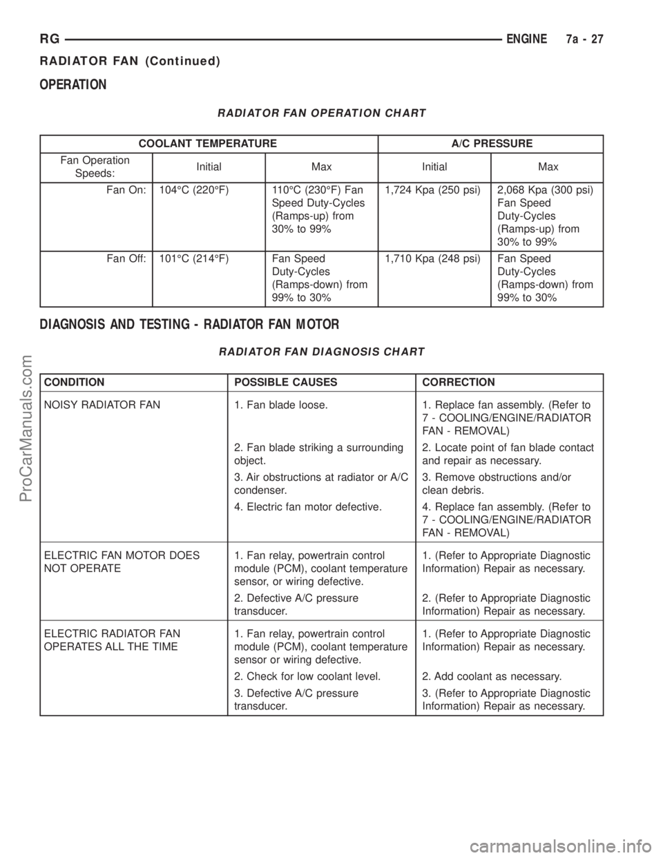
OPERATION
RADIATOR FAN OPERATION CHART
COOLANT TEMPERATURE A/C PRESSURE
Fan Operation
Speeds:Initial Max Initial Max
Fan On: 104ÉC (220ÉF) 110ÉC (230ÉF) Fan
Speed Duty-Cycles
(Ramps-up) from
30% to 99%1,724 Kpa (250 psi) 2,068 Kpa (300 psi)
Fan Speed
Duty-Cycles
(Ramps-up) from
30% to 99%
Fan Off: 101ÉC (214ÉF) Fan Speed
Duty-Cycles
(Ramps-down) from
99% to 30%1,710 Kpa (248 psi) Fan Speed
Duty-Cycles
(Ramps-down) from
99% to 30%
DIAGNOSIS AND TESTING - RADIATOR FAN MOTOR
RADIATOR FAN DIAGNOSIS CHART
CONDITION POSSIBLE CAUSES CORRECTION
NOISY RADIATOR FAN 1. Fan blade loose. 1. Replace fan assembly. (Refer to
7 - COOLING/ENGINE/RADIATOR
FAN - REMOVAL)
2. Fan blade striking a surrounding
object.2. Locate point of fan blade contact
and repair as necessary.
3. Air obstructions at radiator or A/C
condenser.3. Remove obstructions and/or
clean debris.
4. Electric fan motor defective. 4. Replace fan assembly. (Refer to
7 - COOLING/ENGINE/RADIATOR
FAN - REMOVAL)
ELECTRIC FAN MOTOR DOES
NOT OPERATE1. Fan relay, powertrain control
module (PCM), coolant temperature
sensor, or wiring defective.1. (Refer to Appropriate Diagnostic
Information) Repair as necessary.
2. Defective A/C pressure
transducer.2. (Refer to Appropriate Diagnostic
Information) Repair as necessary.
ELECTRIC RADIATOR FAN
OPERATES ALL THE TIME1. Fan relay, powertrain control
module (PCM), coolant temperature
sensor or wiring defective.1. (Refer to Appropriate Diagnostic
Information) Repair as necessary.
2. Check for low coolant level. 2. Add coolant as necessary.
3. Defective A/C pressure
transducer.3. (Refer to Appropriate Diagnostic
Information) Repair as necessary.
RGENGINE7a-27
RADIATOR FAN (Continued)
ProCarManuals.com
Page 318 of 2399
RADIATOR FAN RELAY
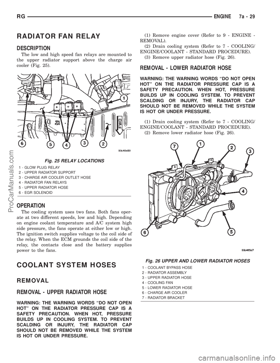
DESCRIPTION
The low and high speed fan relays are mounted to
the upper radiator support above the charge air
cooler (Fig. 25).
OPERATION
The cooling system uses two fans. Both fans oper-
ate at two different speeds, low and high. Depending
on engine coolant temperature and A/C system high
side pressure, the fans operate at either low or high.
The ignition switch supplies voltage to the coil side of
the relay. When the ECM grounds the coil side of the
relay, the contacts close and the battery supplies
power to the fans.
COOLANT SYSTEM HOSES
REMOVAL
REMOVAL - UPPER RADIATOR HOSE
WARNING: THE WARNING WORDS ªDO NOT OPEN
HOTº ON THE RADIATOR PRESSURE CAP IS A
SAFETY PRECAUTION. WHEN HOT, PRESSURE
BUILDS UP IN COOLING SYSTEM. TO PREVENT
SCALDING OR INJURY, THE RADIATOR CAP
SHOULD NOT BE REMOVED WHILE THE SYSTEM
IS HOT OR UNDER PRESSURE.(1) Remove engine cover (Refer to 9 - ENGINE -
REMOVAL).
(2) Drain cooling system (Refer to 7 - COOLING/
ENGINE/COOLANT - STANDARD PROCEDURE).
(3) Remove upper radiator hose (Fig. 26).
REMOVAL - LOWER RADIATOR HOSE
WARNING: THE WARNING WORDS ªDO NOT OPEN
HOTº ON THE RADIATOR PRESSURE CAP IS A
SAFETY PRECAUTION. WHEN HOT, PRESSURE
BUILDS UP IN COOLING SYSTEM. TO PREVENT
SCALDING OR INJURY, THE RADIATOR CAP
SHOULD NOT BE REMOVED WHILE THE SYSTEM
IS HOT OR UNDER PRESSURE.
(1) Drain cooling system (Refer to 7 - COOLING/
ENGINE/COOLANT - STANDARD PROCEDURE).
(2) Remove lower radiator hose (Fig. 26).
Fig. 25 RELAY LOCATIONS
1 - GLOW PLUG RELAY
2 - UPPER RADIATOR SUPPORT
3 - CHARGE AIR COOLER OUTLET HOSE
4 - RADIATOR FAN RELAYS
5 - UPPER RADIATOR HOSE
6 - EGR SOLENOID
Fig. 26 UPPER AND LOWER RADIATOR HOSES
1 - COOLANT BYPASS HOSE
2 - RADIATOR ASSEMBLY
3 - UPPER RADIATOR HOSE
4 - COOLING FAN
5 - LOWER RADIATOR HOSE
6 - CHARGE AIR COOLER
7 - RADIATOR BRACKET
RGENGINE7a-29
ProCarManuals.com
Page 339 of 2399
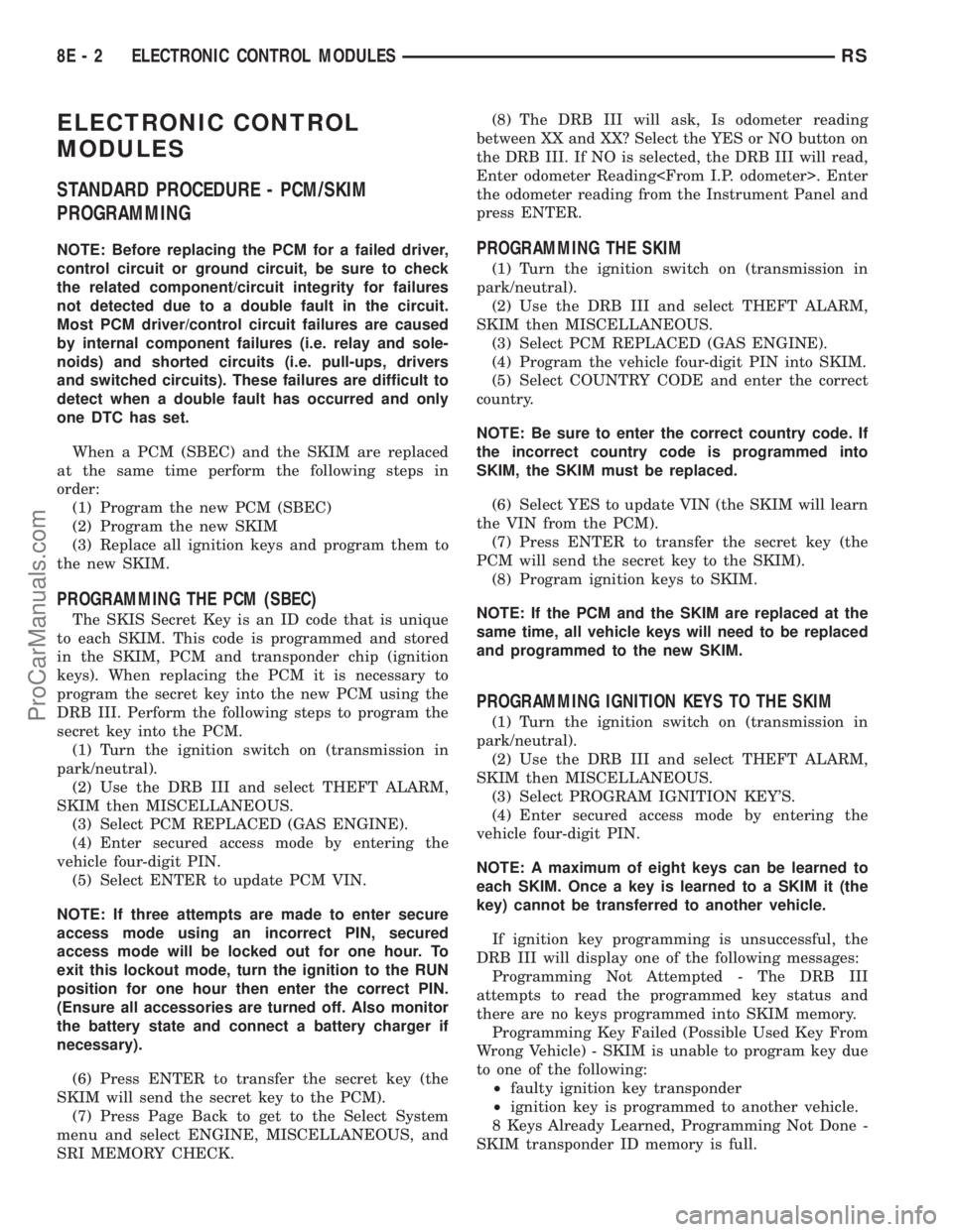
ELECTRONIC CONTROL
MODULES
STANDARD PROCEDURE - PCM/SKIM
PROGRAMMING
NOTE: Before replacing the PCM for a failed driver,
control circuit or ground circuit, be sure to check
the related component/circuit integrity for failures
not detected due to a double fault in the circuit.
Most PCM driver/control circuit failures are caused
by internal component failures (i.e. relay and sole-
noids) and shorted circuits (i.e. pull-ups, drivers
and switched circuits). These failures are difficult to
detect when a double fault has occurred and only
one DTC has set.
When a PCM (SBEC) and the SKIM are replaced
at the same time perform the following steps in
order:
(1) Program the new PCM (SBEC)
(2) Program the new SKIM
(3) Replace all ignition keys and program them to
the new SKIM.
PROGRAMMING THE PCM (SBEC)
The SKIS Secret Key is an ID code that is unique
to each SKIM. This code is programmed and stored
in the SKIM, PCM and transponder chip (ignition
keys). When replacing the PCM it is necessary to
program the secret key into the new PCM using the
DRB III. Perform the following steps to program the
secret key into the PCM.
(1) Turn the ignition switch on (transmission in
park/neutral).
(2) Use the DRB III and select THEFT ALARM,
SKIM then MISCELLANEOUS.
(3) Select PCM REPLACED (GAS ENGINE).
(4) Enter secured access mode by entering the
vehicle four-digit PIN.
(5) Select ENTER to update PCM VIN.
NOTE: If three attempts are made to enter secure
access mode using an incorrect PIN, secured
access mode will be locked out for one hour. To
exit this lockout mode, turn the ignition to the RUN
position for one hour then enter the correct PIN.
(Ensure all accessories are turned off. Also monitor
the battery state and connect a battery charger if
necessary).
(6) Press ENTER to transfer the secret key (the
SKIM will send the secret key to the PCM).
(7) Press Page Back to get to the Select System
menu and select ENGINE, MISCELLANEOUS, and
SRI MEMORY CHECK.(8) The DRB III will ask, Is odometer reading
between XX and XX? Select the YES or NO button on
the DRB III. If NO is selected, the DRB III will read,
Enter odometer Reading
the odometer reading from the Instrument Panel and
press ENTER.
PROGRAMMING THE SKIM
(1) Turn the ignition switch on (transmission in
park/neutral).
(2) Use the DRB III and select THEFT ALARM,
SKIM then MISCELLANEOUS.
(3) Select PCM REPLACED (GAS ENGINE).
(4) Program the vehicle four-digit PIN into SKIM.
(5) Select COUNTRY CODE and enter the correct
country.
NOTE: Be sure to enter the correct country code. If
the incorrect country code is programmed into
SKIM, the SKIM must be replaced.
(6) Select YES to update VIN (the SKIM will learn
the VIN from the PCM).
(7) Press ENTER to transfer the secret key (the
PCM will send the secret key to the SKIM).
(8) Program ignition keys to SKIM.
NOTE: If the PCM and the SKIM are replaced at the
same time, all vehicle keys will need to be replaced
and programmed to the new SKIM.
PROGRAMMING IGNITION KEYS TO THE SKIM
(1) Turn the ignition switch on (transmission in
park/neutral).
(2) Use the DRB III and select THEFT ALARM,
SKIM then MISCELLANEOUS.
(3) Select PROGRAM IGNITION KEY'S.
(4) Enter secured access mode by entering the
vehicle four-digit PIN.
NOTE: A maximum of eight keys can be learned to
each SKIM. Once a key is learned to a SKIM it (the
key) cannot be transferred to another vehicle.
If ignition key programming is unsuccessful, the
DRB III will display one of the following messages:
Programming Not Attempted - The DRB III
attempts to read the programmed key status and
there are no keys programmed into SKIM memory.
Programming Key Failed (Possible Used Key From
Wrong Vehicle) - SKIM is unable to program key due
to one of the following:
²faulty ignition key transponder
²ignition key is programmed to another vehicle.
8 Keys Already Learned, Programming Not Done -
SKIM transponder ID memory is full.
8E - 2 ELECTRONIC CONTROL MODULESRS
ProCarManuals.com
Page 344 of 2399
(9) Connect a DRBIIItto the vehicle and initialize
the system.
DATA LINK CONNECTOR
DESCRIPTION
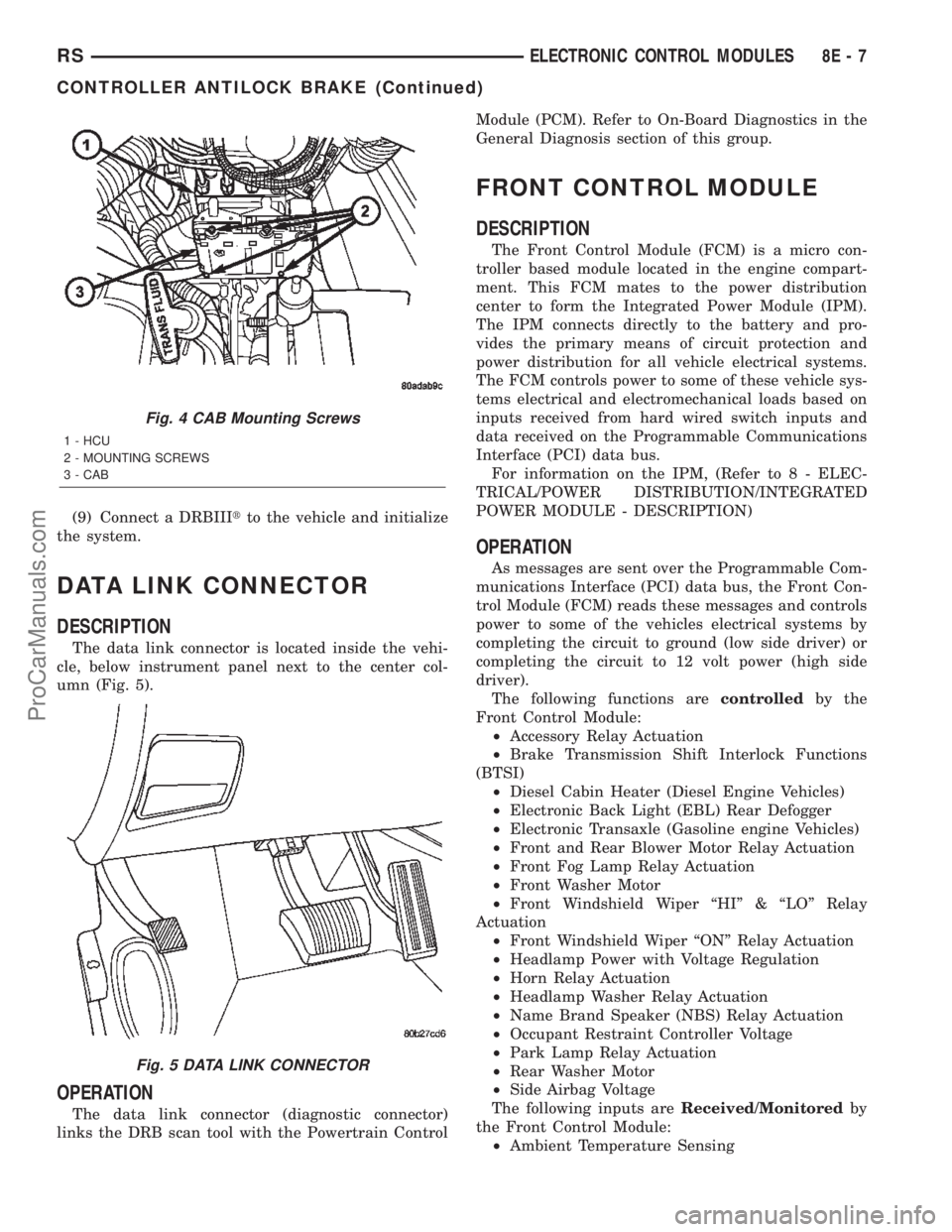
The data link connector is located inside the vehi-
cle, below instrument panel next to the center col-
umn (Fig. 5).
OPERATION
The data link connector (diagnostic connector)
links the DRB scan tool with the Powertrain ControlModule (PCM). Refer to On-Board Diagnostics in the
General Diagnosis section of this group.
FRONT CONTROL MODULE
DESCRIPTION
The Front Control Module (FCM) is a micro con-
troller based module located in the engine compart-
ment. This FCM mates to the power distribution
center to form the Integrated Power Module (IPM).
The IPM connects directly to the battery and pro-
vides the primary means of circuit protection and
power distribution for all vehicle electrical systems.
The FCM controls power to some of these vehicle sys-
tems electrical and electromechanical loads based on
inputs received from hard wired switch inputs and
data received on the Programmable Communications
Interface (PCI) data bus.
For information on the IPM, (Refer to 8 - ELEC-
TRICAL/POWER DISTRIBUTION/INTEGRATED
POWER MODULE - DESCRIPTION)
OPERATION
As messages are sent over the Programmable Com-
munications Interface (PCI) data bus, the Front Con-
trol Module (FCM) reads these messages and controls
power to some of the vehicles electrical systems by
completing the circuit to ground (low side driver) or
completing the circuit to 12 volt power (high side
driver).
The following functions arecontrolledby the
Front Control Module:
²Accessory Relay Actuation
²Brake Transmission Shift Interlock Functions
(BTSI)
²Diesel Cabin Heater (Diesel Engine Vehicles)
²Electronic Back Light (EBL) Rear Defogger
²Electronic Transaxle (Gasoline engine Vehicles)
²Front and Rear Blower Motor Relay Actuation
²Front Fog Lamp Relay Actuation
²Front Washer Motor
²Front Windshield Wiper ªHIº & ªLOº Relay
Actuation
²Front Windshield Wiper ªONº Relay Actuation
²Headlamp Power with Voltage Regulation
²Horn Relay Actuation
²Headlamp Washer Relay Actuation
²Name Brand Speaker (NBS) Relay Actuation
²Occupant Restraint Controller Voltage
²Park Lamp Relay Actuation
²Rear Washer Motor
²Side Airbag Voltage
The following inputs areReceived/Monitoredby
the Front Control Module:
²Ambient Temperature Sensing
Fig. 4 CAB Mounting Screws
1 - HCU
2 - MOUNTING SCREWS
3 - CAB
Fig. 5 DATA LINK CONNECTOR
RSELECTRONIC CONTROL MODULES8E-7
CONTROLLER ANTILOCK BRAKE (Continued)
ProCarManuals.com
Page 346 of 2399
(4) Install the battery in the vehicle. Refer to the
procedure in Battery Systems.
(5) Connect the positive and negative battery
cables.
(6) Using the DRB IIIt, under ªFRONT CON-
TROL MODULEº then ªMISCº program the EQ
curve of the radio into the Front Control Module.
Refer to the appropriate diagnostic manual.
NOTE: If the vehicle is not equipped with Name
Brand Speakers (Infinity, etc.) or Headlamp Washers
the DRB IIITmust be used to Disable the appropri-
ate relays in the Intelligent Power Module Assembly.
HEATED SEAT MODULE
DESCRIPTION
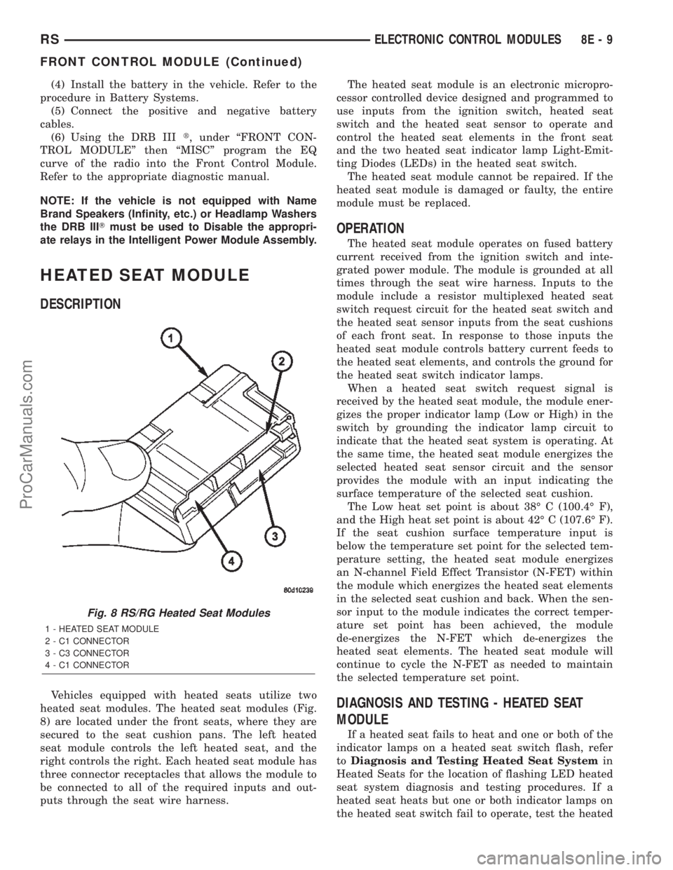
Vehicles equipped with heated seats utilize two
heated seat modules. The heated seat modules (Fig.
8) are located under the front seats, where they are
secured to the seat cushion pans. The left heated
seat module controls the left heated seat, and the
right controls the right. Each heated seat module has
three connector receptacles that allows the module to
be connected to all of the required inputs and out-
puts through the seat wire harness.The heated seat module is an electronic micropro-
cessor controlled device designed and programmed to
use inputs from the ignition switch, heated seat
switch and the heated seat sensor to operate and
control the heated seat elements in the front seat
and the two heated seat indicator lamp Light-Emit-
ting Diodes (LEDs) in the heated seat switch.
The heated seat module cannot be repaired. If the
heated seat module is damaged or faulty, the entire
module must be replaced.
OPERATION
The heated seat module operates on fused battery
current received from the ignition switch and inte-
grated power module. The module is grounded at all
times through the seat wire harness. Inputs to the
module include a resistor multiplexed heated seat
switch request circuit for the heated seat switch and
the heated seat sensor inputs from the seat cushions
of each front seat. In response to those inputs the
heated seat module controls battery current feeds to
the heated seat elements, and controls the ground for
the heated seat switch indicator lamps.
When a heated seat switch request signal is
received by the heated seat module, the module ener-
gizes the proper indicator lamp (Low or High) in the
switch by grounding the indicator lamp circuit to
indicate that the heated seat system is operating. At
the same time, the heated seat module energizes the
selected heated seat sensor circuit and the sensor
provides the module with an input indicating the
surface temperature of the selected seat cushion.
The Low heat set point is about 38É C (100.4É F),
and the High heat set point is about 42É C (107.6É F).
If the seat cushion surface temperature input is
below the temperature set point for the selected tem-
perature setting, the heated seat module energizes
an N-channel Field Effect Transistor (N-FET) within
the module which energizes the heated seat elements
in the selected seat cushion and back. When the sen-
sor input to the module indicates the correct temper-
ature set point has been achieved, the module
de-energizes the N-FET which de-energizes the
heated seat elements. The heated seat module will
continue to cycle the N-FET as needed to maintain
the selected temperature set point.
DIAGNOSIS AND TESTING - HEATED SEAT
MODULE
If a heated seat fails to heat and one or both of the
indicator lamps on a heated seat switch flash, refer
toDiagnosis and Testing Heated Seat Systemin
Heated Seats for the location of flashing LED heated
seat system diagnosis and testing procedures. If a
heated seat heats but one or both indicator lamps on
the heated seat switch fail to operate, test the heated
Fig. 8 RS/RG Heated Seat Modules
1 - HEATED SEAT MODULE
2 - C1 CONNECTOR
3 - C3 CONNECTOR
4 - C1 CONNECTOR
RSELECTRONIC CONTROL MODULES8E-9
FRONT CONTROL MODULE (Continued)
ProCarManuals.com
Page 348 of 2399
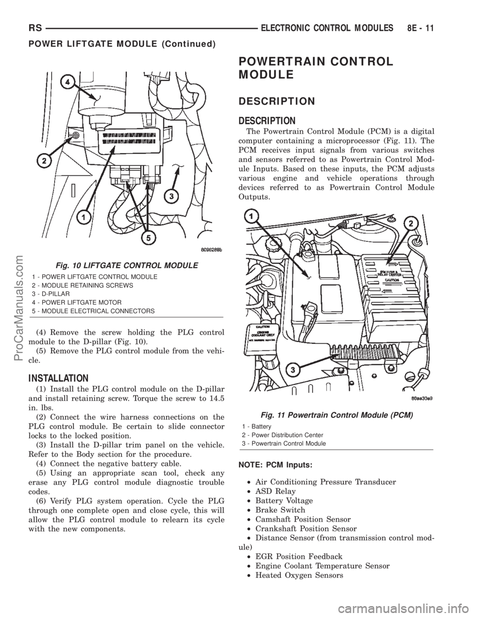
(4) Remove the screw holding the PLG control
module to the D-pillar (Fig. 10).
(5) Remove the PLG control module from the vehi-
cle.
INSTALLATION
(1) Install the PLG control module on the D-pillar
and install retaining screw. Torque the screw to 14.5
in. lbs.
(2) Connect the wire harness connections on the
PLG control module. Be certain to slide connector
locks to the locked position.
(3) Install the D-pillar trim panel on the vehicle.
Refer to the Body section for the procedure.
(4) Connect the negative battery cable.
(5) Using an appropriate scan tool, check any
erase any PLG control module diagnostic trouble
codes.
(6) Verify PLG system operation. Cycle the PLG
through one complete open and close cycle, this will
allow the PLG control module to relearn its cycle
with the new components.
POWERTRAIN CONTROL
MODULE
DESCRIPTION
DESCRIPTION
The Powertrain Control Module (PCM) is a digital
computer containing a microprocessor (Fig. 11). The
PCM receives input signals from various switches
and sensors referred to as Powertrain Control Mod-
ule Inputs. Based on these inputs, the PCM adjusts
various engine and vehicle operations through
devices referred to as Powertrain Control Module
Outputs.
NOTE: PCM Inputs:
²Air Conditioning Pressure Transducer
²ASD Relay
²Battery Voltage
²Brake Switch
²Camshaft Position Sensor
²Crankshaft Position Sensor
²Distance Sensor (from transmission control mod-
ule)
²EGR Position Feedback
²Engine Coolant Temperature Sensor
²Heated Oxygen Sensors
Fig. 10 LIFTGATE CONTROL MODULE
1 - POWER LIFTGATE CONTROL MODULE
2 - MODULE RETAINING SCREWS
3 - D-PILLAR
4 - POWER LIFTGATE MOTOR
5 - MODULE ELECTRICAL CONNECTORS
Fig. 11 Powertrain Control Module (PCM)
1 - Battery
2 - Power Distribution Center
3 - Powertrain Control Module
RSELECTRONIC CONTROL MODULES8E-11
POWER LIFTGATE MODULE (Continued)
ProCarManuals.com