CHRYSLER TOWN AND COUNTRY 2008 5.G Owners Manual
Manufacturer: CHRYSLER, Model Year: 2008, Model line: TOWN AND COUNTRY, Model: CHRYSLER TOWN AND COUNTRY 2008 5.GPages: 531, PDF Size: 4.51 MB
Page 351 of 531
DRIVING THROUGH WATER
Driving through water more than a few inches/
centimeters deep will require extra caution to ensure
safety and prevent damage to your vehicle.
Flowing/Rising Water
WARNING!
Do not drive on, or cross, a road or a path where
water is flowing and/or rising (as in storm run-off).
Flowing water can wear away the road or path's
surface and cause your vehicle to sink into deeper
water. Furthermore, flowing and/or rising water can
carry your vehicle away swiftly. Failure to follow this
warning may result in injuries that are serious or
fatal to you, your passengers, and others around you.
Shallow Standing Water
Although your vehicle is capable of driving through
shallow standing water, consider the following Caution
and Warning before doing so.
CAUTION!
²Always check the depth of the standing water
before driving through it. Never drive through
standing water that is deeper than the bottom of
the tire rims mounted on the vehicle.
²Determine the condition of the road or the path
that is under water, and if there are any obstacles
in the way, before driving through the standing
water.
²Do not exceed 5 mph (8 km/h) when driving
through standing water. This will minimize wave
effects.
STARTING AND OPERATING 349
5
Page 352 of 531
CAUTION!
²Driving through standing water may cause dam-
age to your vehicle's drivetrain components. Al-
ways inspect your vehicle's fluids (i.e., engine oil,
transmission, axle, etc.) for signs of contamination
(i.e., fluid that is milky or foamy in appearance)
after driving through standing water. Do not con-
tinue to operate the vehicle if any fluid appears
contaminated, as this may result in further dam-
age. Such damage is not covered by the New
Vehicle Limited Warranty.
²Getting water inside your vehicle's engine can
cause it to lock up and stall out, and cause serious
internal damage to the engine. Such damage is not
covered by the New Vehicle Limited Warranty.
WARNING!
²Driving through standing water limits your vehi-
cle's traction capabilities. Do not exceed 5 mph (8
km/h) when driving through standing water.
²Driving through standing water limits your vehi-
cle's braking capabilities, which increases stop-
ping distances. Therefore, after driving through
standing water, drive slowly and lightly press on
the brake pedal several times to dry the brakes.
²Getting water inside your vehicle's engine can
cause it to lock up and stall out, and leave you
stranded.
²Failure to follow these warnings may result in
injuries that are serious or fatal to you, your
passengers, and others around you.
350 STARTING AND OPERATING
Page 353 of 531
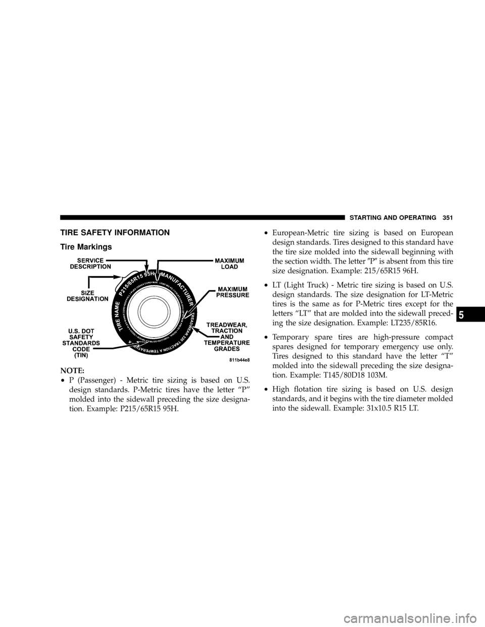
TIRE SAFETY INFORMATION
Tire Markings
NOTE:
²P (Passenger) - Metric tire sizing is based on U.S.
design standards. P-Metric tires have the letter ªPº
molded into the sidewall preceding the size designa-
tion. Example: P215/65R15 95H.
²European-Metric tire sizing is based on European
design standards. Tires designed to this standard have
the tire size molded into the sidewall beginning with
the section width. The letter9P9is absent from this tire
size designation. Example: 215/65R15 96H.
²LT (Light Truck) - Metric tire sizing is based on U.S.
design standards. The size designation for LT-Metric
tires is the same as for P-Metric tires except for the
letters ªLTº that are molded into the sidewall preced-
ing the size designation. Example: LT235/85R16.
²Temporary spare tires are high-pressure compact
spares designed for temporary emergency use only.
Tires designed to this standard have the letter ªTº
molded into the sidewall preceding the size designa-
tion. Example: T145/80D18 103M.
²High flotation tire sizing is based on U.S. design
standards, and it begins with the tire diameter molded
into the sidewall. Example: 31x10.5 R15 LT.
STARTING AND OPERATING 351
5
Page 354 of 531
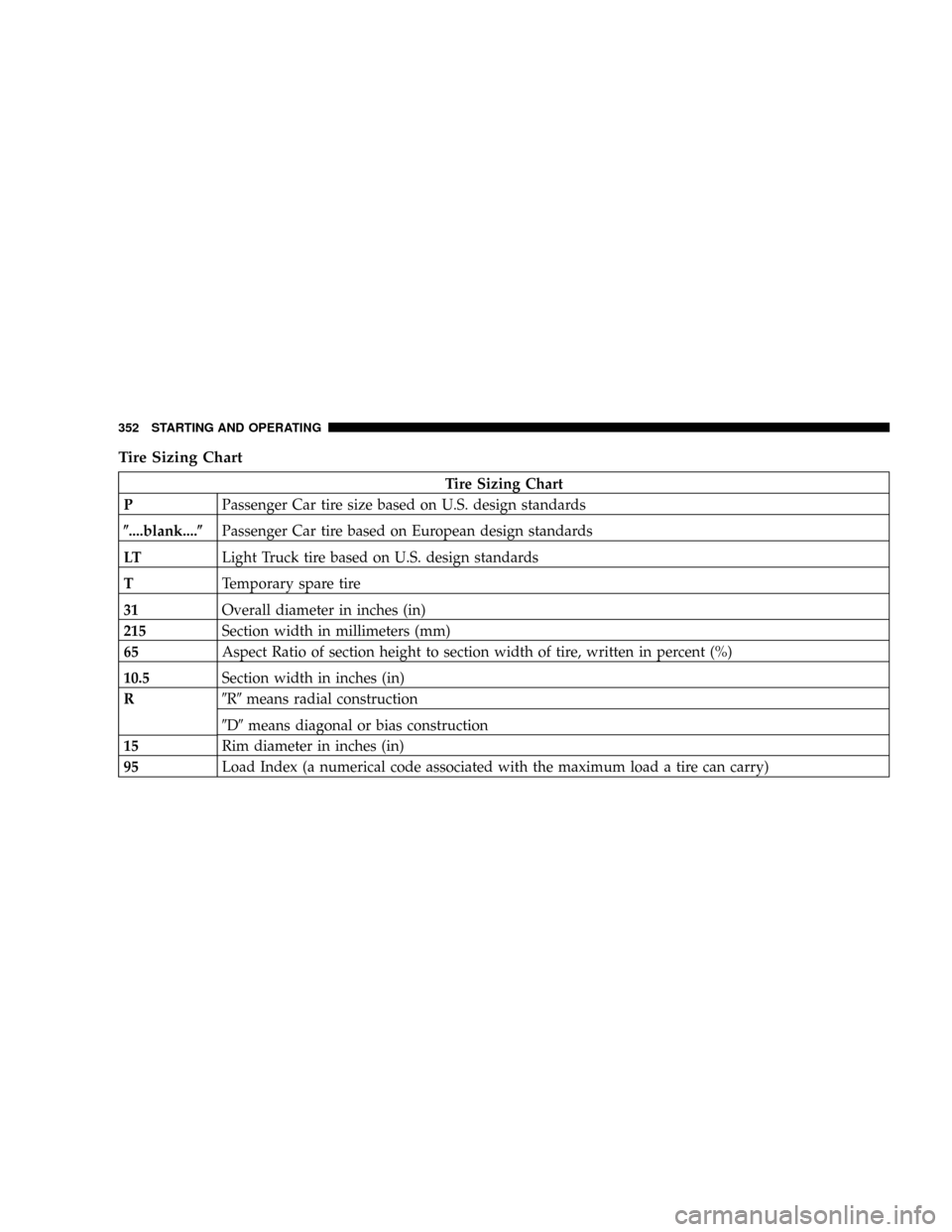
Tire Sizing Chart
Tire Sizing Chart
PPassenger Car tire size based on U.S. design standards
(....blank....(Passenger Car tire based on European design standards
LTLight Truck tire based on U.S. design standards
TTemporary spare tire
31Overall diameter in inches (in)
215Section width in millimeters (mm)
65Aspect Ratio of section height to section width of tire, written in percent (%)
10.5Section width in inches (in)
R9R9means radial construction
9D9means diagonal or bias construction
15Rim diameter in inches (in)
95Load Index (a numerical code associated with the maximum load a tire can carry)
352 STARTING AND OPERATING
Page 355 of 531
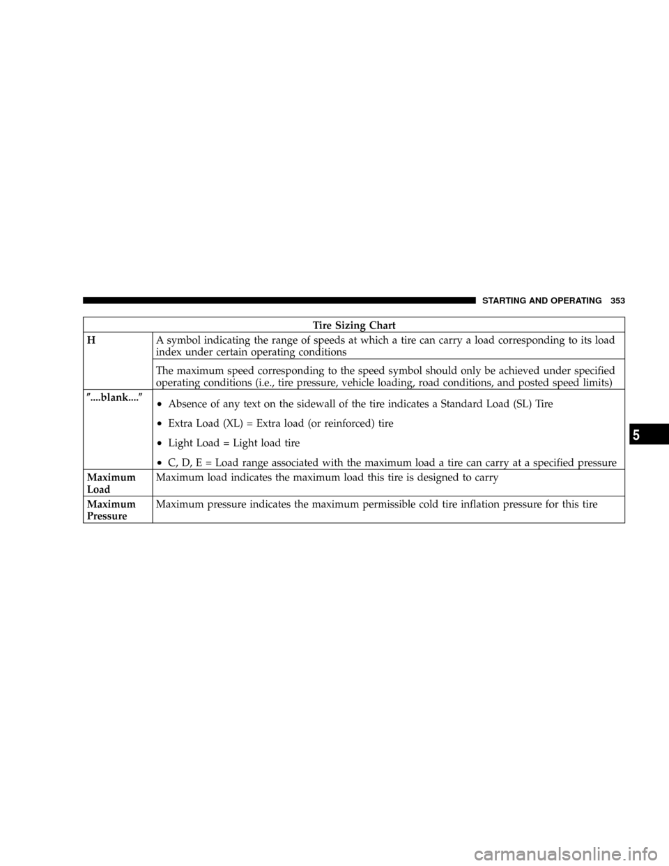
Tire Sizing Chart
HA symbol indicating the range of speeds at which a tire can carry a load corresponding to its load
index under certain operating conditions
The maximum speed corresponding to the speed symbol should only be achieved under specified
operating conditions (i.e., tire pressure, vehicle loading, road conditions, and posted speed limits)
(....blank....(
²Absence of any text on the sidewall of the tire indicates a Standard Load (SL) Tire
²Extra Load (XL) = Extra load (or reinforced) tire
²Light Load = Light load tire
²C, D, E = Load range associated with the maximum load a tire can carry at a specified pressure
Maximum
LoadMaximum load indicates the maximum load this tire is designed to carry
Maximum
PressureMaximum pressure indicates the maximum permissible cold tire inflation pressure for this tire
STARTING AND OPERATING 353
5
Page 356 of 531
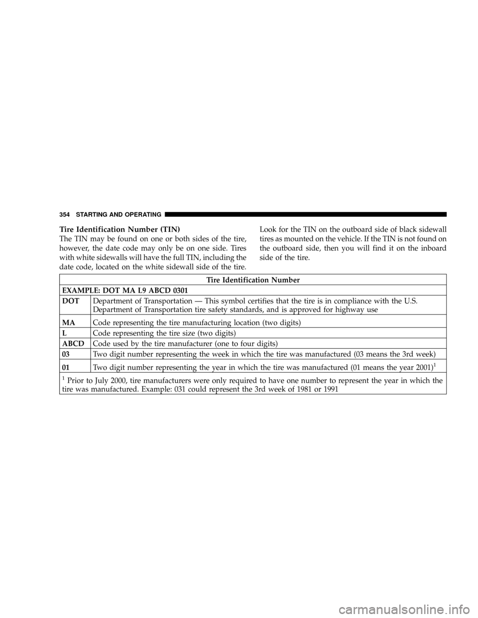
Tire Identification Number (TIN)
The TIN may be found on one or both sides of the tire,
however, the date code may only be on one side. Tires
with white sidewalls will have the full TIN, including the
date code, located on the white sidewall side of the tire.Look for the TIN on the outboard side of black sidewall
tires as mounted on the vehicle. If the TIN is not found on
the outboard side, then you will find it on the inboard
side of the tire.
Tire Identification Number
EXAMPLE: DOT MA L9 ABCD 0301
DOTDepartment of Transportation Ð This symbol certifies that the tire is in compliance with the U.S.
Department of Transportation tire safety standards, and is approved for highway use
MACode representing the tire manufacturing location (two digits)
LCode representing the tire size (two digits)
ABCDCode used by the tire manufacturer (one to four digits)
03Two digit number representing the week in which the tire was manufactured (03 means the 3rd week)
01Two digit number representing the year in which the tire was manufactured (01 means the year 2001)
1
1
Prior to July 2000, tire manufacturers were only required to have one number to represent the year in which the
tire was manufactured. Example: 031 could represent the 3rd week of 1981 or 1991
354 STARTING AND OPERATING
Page 357 of 531
Tire Loading and Tire Pressure
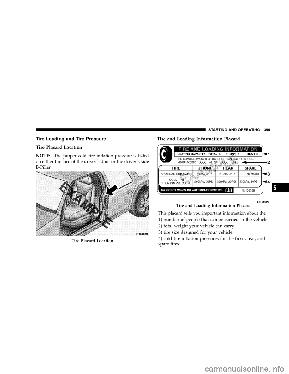
Tire Placard Location
NOTE:The proper cold tire inflation pressure is listed
on either the face of the driver's door or the driver's side
B-Pillar.
Tire and Loading Information Placard
This placard tells you important information about the:
1) number of people that can be carried in the vehicle
2) total weight your vehicle can carry
3) tire size designed for your vehicle
4) cold tire inflation pressures for the front, rear, and
spare tires.
Tire Placard Location
Tire and Loading Information Placard
STARTING AND OPERATING 355
5
Page 358 of 531
Loading
The vehicle maximum load on the tire must not exceed
the load carrying capacity of the tire on your vehicle. You
will not exceed the tire's load carrying capacity if you
adhere to the loading conditions, tire size, and cold tire
inflation pressures specified on the Tire and Loading
Information placard and in the ªVehicle Loadingº section
of this manual.
NOTE:Under a maximum loaded vehicle condition,
gross axle weight ratings (GAWRs) for the front and rear
axles must not be exceeded. For further information on
GAWRs, vehicle loading, and trailer towing, refer to
ªVehicle Loadingº in this section.
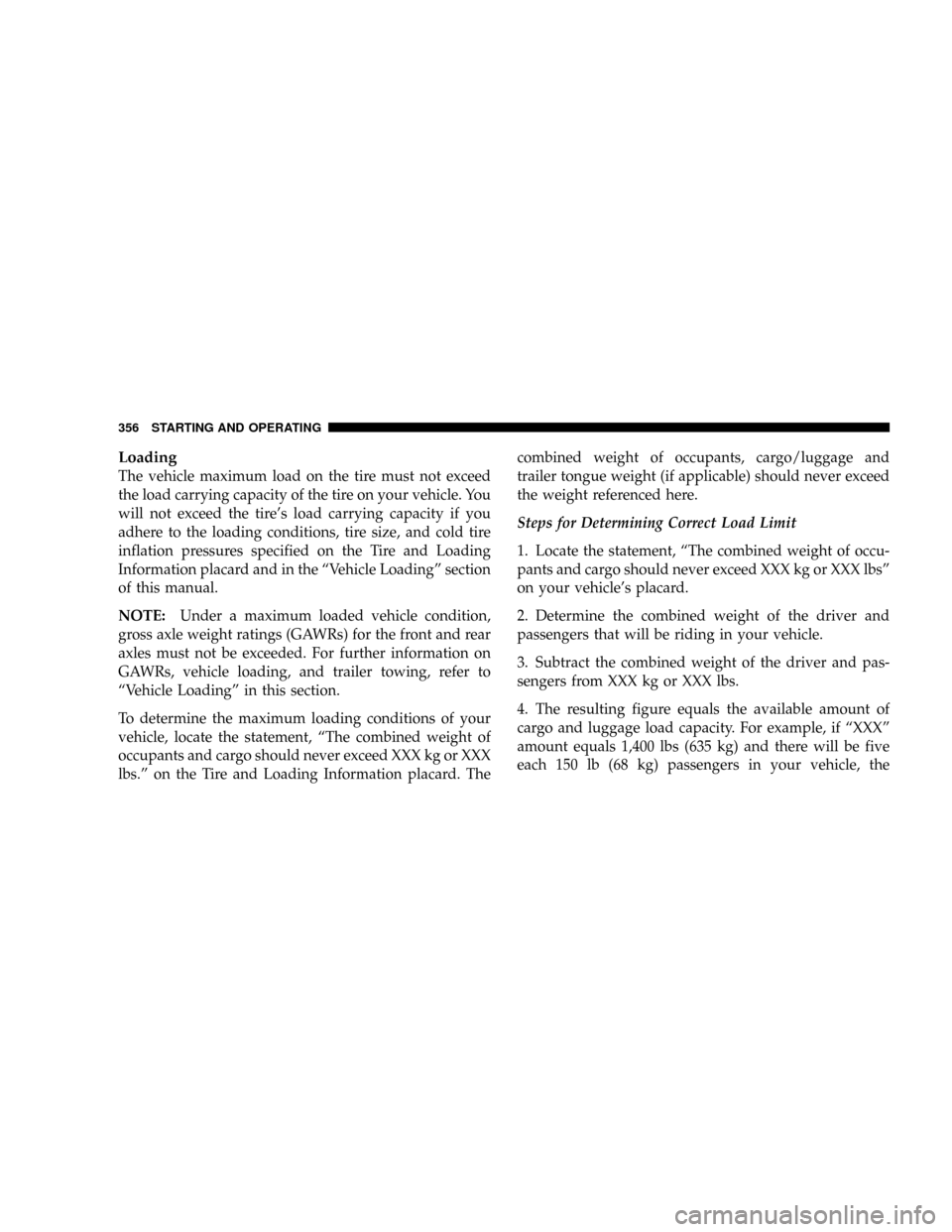
To determine the maximum loading conditions of your
vehicle, locate the statement, ªThe combined weight of
occupants and cargo should never exceed XXX kg or XXX
lbs.º on the Tire and Loading Information placard. Thecombined weight of occupants, cargo/luggage and
trailer tongue weight (if applicable) should never exceed
the weight referenced here.
Steps for Determining Correct Load Limit
1. Locate the statement, ªThe combined weight of occu-
pants and cargo should never exceed XXX kg or XXX lbsº
on your vehicle's placard.
2. Determine the combined weight of the driver and
passengers that will be riding in your vehicle.
3. Subtract the combined weight of the driver and pas-
sengers from XXX kg or XXX lbs.
4. The resulting figure equals the available amount of
cargo and luggage load capacity. For example, if ªXXXº
amount equals 1,400 lbs (635 kg) and there will be five
each 150 lb (68 kg) passengers in your vehicle, the
356 STARTING AND OPERATING
Page 359 of 531
![CHRYSLER TOWN AND COUNTRY 2008 5.G Owners Manual amount of available cargo and luggage load capacity is
650 lbs (295 kg) (since 5 x 150 = 750, and 1400 ± 750 = 650
lbs [295 kg]).
5. Determine the combined weight of luggage and cargo
being loaded on CHRYSLER TOWN AND COUNTRY 2008 5.G Owners Manual amount of available cargo and luggage load capacity is
650 lbs (295 kg) (since 5 x 150 = 750, and 1400 ± 750 = 650
lbs [295 kg]).
5. Determine the combined weight of luggage and cargo
being loaded on](/img/25/8557/w960_8557-358.png)
amount of available cargo and luggage load capacity is
650 lbs (295 kg) (since 5 x 150 = 750, and 1400 ± 750 = 650
lbs [295 kg]).
5. Determine the combined weight of luggage and cargo
being loaded on the vehicle. That weight may not safely
exceed the available cargo and luggage load capacity
calculated in Step 4.
6. If your vehicle will be towing a trailer, load from your
trailer will be transferred to your vehicle. Consult this
manual to determine how this reduces the available
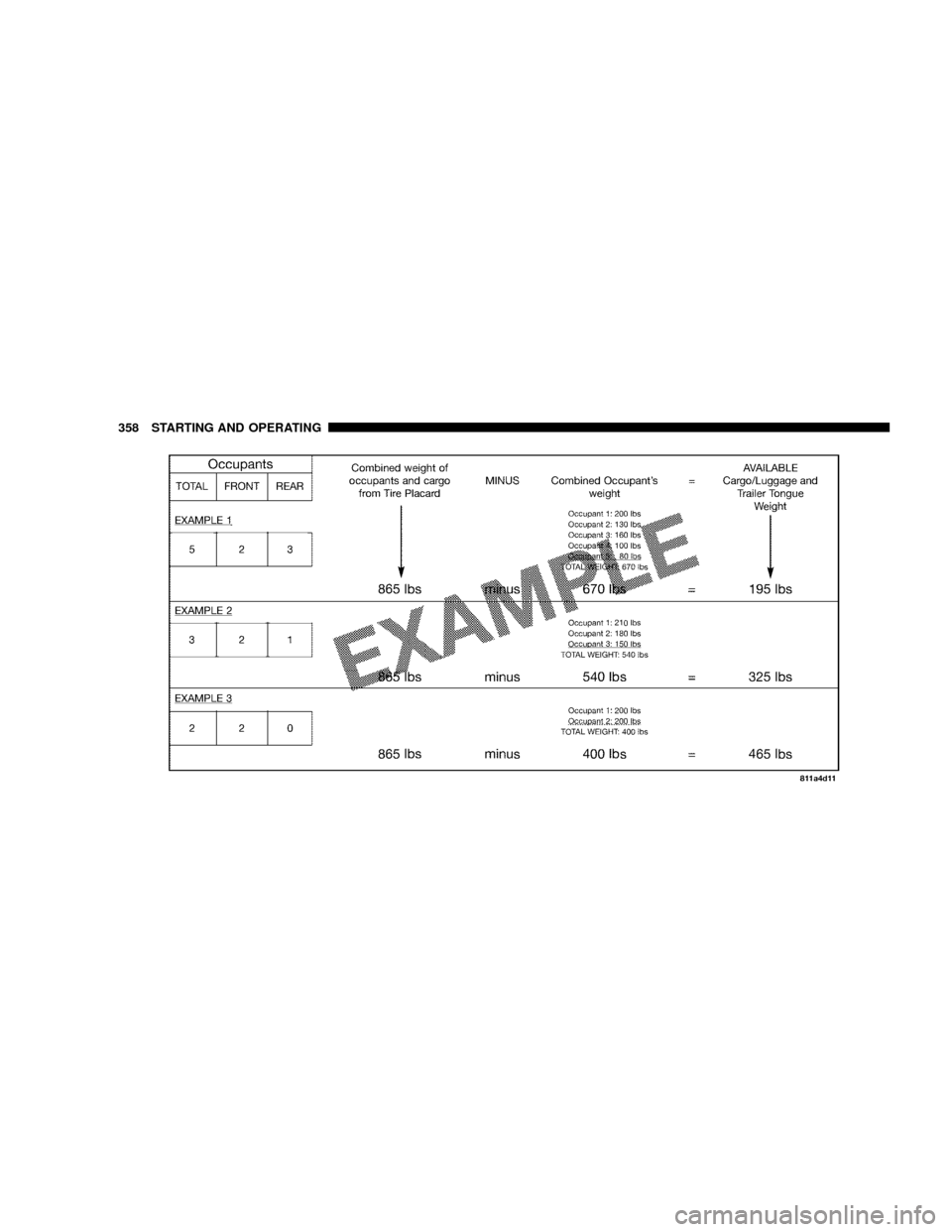
cargo and luggage load capacity of your vehicle.NOTE:The following table shows examples on how to
calculate total load, cargo/luggage, and towing capaci-
ties of your vehicle with varying seating configurations
and number and size of occupants. This table is for
illustration purposes only and may not be accurate for
the seating and load carrying capacity of your vehicle.
NOTE:For the following example, the combined weight
of occupants and cargo should never exceed 865 lbs (392
kg).
STARTING AND OPERATING 357
5
Page 360 of 531
358 STARTING AND OPERATING