tow CHRYSLER TOWN AND COUNTRY 2013 5.G User Guide
[x] Cancel search | Manufacturer: CHRYSLER, Model Year: 2013, Model line: TOWN AND COUNTRY, Model: CHRYSLER TOWN AND COUNTRY 2013 5.GPages: 140, PDF Size: 4.18 MB
Page 1 of 140

13Y531-926-A A • TOWN & COuNTr y • Third Ed iTiO N • usEr g uidE
���3 u s E r guid E
T
hE C
hr
Ys
LE
r
TOWN & CO u NT ry
G et the f r ee m o bile app f o r y o ur pho nehttp:/ / gettag.mobiu.s. onlyCanada Only
iPhoneCanada Only Android
To put Microsoft Tags to work for you, use your mobile phone’s browser
or App store to download a Microsoft Tag reader, like the free one at www.gettag.mobi. Then follow the directions to scan the code.
Download a FrEE Vehicle Information App
by visiting your application store, Keyword (Chrysler Concierge),
or scanning the Microsoft Tag.
Download a FrEE electronic copy
of the Owner’s Manual or Warranty Booklet by visiting the Owners tab at:
www.chrysler.com (
u
.
s
.) or
www.chrysler.ca (Canada).
Page 3 of 140

INTRODUCTION/WELCOME
WELCOME FROM CHRYSLER
GROUPLLC ..................3
CONTROLS AT A GLANCE
DRIVER COCKPIT...............6
INSTRUMENT CLUSTER ...........8
GETTING STARTED
KEYFOB ....................10
REMOTE START...............12
KEYLESS ENTER-N-GO™ ...........12
THEFT ALARM ................15
SEATBELT ...................16
SUPPLEMENTAL RESTRAINT
SYSTEM (SRS) — AIR BAGS .........17
CHILD RESTRAINTS .............18
FRONTSEATS ................20
REAR SEATS ..................21
HEATEDSEATS ................25
HEATED STEERING WHEEL ........26
TILT/TELESCOPING STEERING
COLUMN ...................27
ADJUSTABLE PEDALS ............27
OPERATING YOUR VEHICLE
ENGINE BREAK-IN
RECOMMENDATIONS............28
TURN SIGNAL/WIPER/WASHER/
HIGH BEAM LEVER ..............28
HEADLIGHT SWITCH AND HALO
LIGHTSWITCH ................30
SPEED CONTROL ...............31
ELECTRONIC RANGE SELECTION (ERS) . . 32FUEL ECONOMY (ECON) MODE .....33
MANUAL CLIMATE CONTROLS ......34
THREE ZONE MANUAL CLIMATE
CONTROLS ..................35
THREE ZONE AUTOMATIC
TEMPERATURE CONTROLS (ATC) ....36
PARKSENSE® REAR PARK ASSIST .....38
PARKVIEW® REAR BACK-UP CAMERA . . 38
BLIND SPOT MONITORING WITH
REAR CROSS PATH ..............38
POWER SLIDING SIDE DOORS . . . ....39
POWERLIFTGATE ..............39
POWER SUNROOF . . . ..........40
WIND BUFFETING ..............41
ELECTRONICS
YOUR VEHICLE'S SOUND SYSTEM ....42
Uconnect® 130 .................44
Uconnect® 130 WITH SiriusXM SATELLITE
RADIO .....................46 Uconnect® 430/430N
..............49
Uconnect® 730N ................59
SiriusXM SATELLITE RADIO/TRAVEL
LINK ......................70
STEERING WHEEL AUDIO
CONTROLS ..................73
SETTING THE ANALOG CLOCK . . . . . 73
iPod®/USB/MP3 CONTROL .........74
Uconnect® Phone ................75
Uconnect® VOICE COMMAND . . . ....77
Bluetooth® STREAMING AUDIO . . . . . . 80
VIDEO ENTERTAINMENT
SYSTEM (VES™) ................80
ELECTRONIC VEHICLE
INFORMATION CENTER (EVIC) ......82
PROGRAMMABLE FEATURES .......82
UNIVERSAL GARAGE DOOR OPENER
(HomeLink®) ..................84
POWER INVERTER ..............86
POWER OUTLETS ..............87
UTILITY
IN-FLOOR STORAGE – STOW'N GO® . . . 89
ROOF LUGGAGE RACK ..........89
TRAILER TOWING WEIGHTS
(MAXIMUM TRAILER WEIGHT
RATINGS) ...................90
RECREATIONAL TOWING
(BEHIND MOTORHOME, ETC.) ......90
WHAT TO DO IN EMERGENCIES
ROADSIDE ASSISTANCE...........91
INSTRUMENT CLUSTER WARNING
LIGHTS .....................91
IF YOUR ENGINE OVERHEATS . . . ....95
JACKING AND TIRE CHANGING . . . . . 96
JUMP-STARTING . . ............106
SHIFT LEVER OVERRIDE . . .......108
TOWING A DISABLED VEHICLE . . . . . 108
FREEING A STUCK VEHICLE .......108
EVENT DATA RECORDER (EDR) . . . . . 109
MAINTAINING YOUR VEHICLE
OPENING THE HOOD ...........110
ADDING FUEL . . ..............111
ENGINE COMPARTMENT .........112
FLUIDSANDCAPACITIES .........113
MAINTENANCE SCHEDULE .......114
MAINTENANCE RECORD .........118
FUSES .....................119
TIRE PRESSURES ...............122
WHEEL AND WHEEL TRIM CARE . . . . . 123
EXTERIOR BULBS ..............123
TABLE OF CONTENTS
Page 23 of 140

• Place the ignition switch in the ON position, select Remote Linked to Memory in theElectronic Vehicle Information Center (EVIC) and enter Yes.
• Press 1 or 2 to recall the saved positions, or press UNLOCK on the programmed Key Fob.
CAUTION!
Do not place any article under a power seat or impede its ability to move as it may cause
damage to the seat controls. Seat travel may become limited if movement is stopped by an
obstruction in the seat’s path.
WARNING!
• Adjusting a seat while the vehicle is moving is dangerous. The sudden movement of the seat could cause you to lose control. The seat belt might not be properly adjusted, and you
could be severely injured or killed. Only adjust a seat while the vehicle is parked.
• Do not ride with the seatback reclined so that the seat belt is no longer resting against your
chest. In a collision, you could slide under the seat belt and be severely injured or killed.
Use the recliner only when the vehicle is parked.
REAR SEATS
Second Row Seats – Stow 'n Go®
•On vehicles equipped with Stow 'n Go® seats,
the seats will fold and tumble in one motion.
• Move the front seat fully forward.
• Recline the front seatback fully forward.
• Raise the armrests on the second row seat.
NOTE:
Seat will not stow in the storage bin unless the
armrests are raised.
• Slide the storage bin locking mechanism to the “LOCK” position and then pull up on the
storage bin latch to open the cover.
GETTING STARTED
21
Page 24 of 140

• Pull upward on the seatback recliner leverlocated on the outboard side of the seat.
• The non-adjustable head restraint and seat- back will fold automatically during the seat
tumble.
•
The seat will automatically tumble into posi-
tion for easy storage.
• Push the seat into the storage bin and close the storage bin cover.
To Unstow Second Row Seats
• Pull up on the storage bin latch to open thecover.
• Pull up on the strap to lift the seat out of the storage bin and push the seat rearward to
latch the seat anchors.
• Lift the seatback to the full upright position.
• Return the head restraint to its upright posi- tion, close the storage bin cover and slide
the storage bin locking mechanism to the
“Unlocked” position.
GETTING STARTED
22
Page 25 of 140

Third Row Seats
Third Row Power Recliner
• The power recline feature, located on the side of the seat cushion, adjusts the seatback angleforward/rearward for occupant comfort.
Third Row Power Seat Switch
NOTE:
•
Disconnect the center shoulder belt from the
small buckle and lower the head restraints
before attempting to fold/stow the power
third row seats.
• A one-touch power folding seat switch is located in the left rear trim panel as part of a
switch bank.
• Left and right third row seats can be folded individually or together. The third row power
folding seats adjust to multiple positions.
• The switch is only functional when the lift- gate is open and the vehicle is in PARK.
• To abort seat operation while the seat is in motion, press a different seat position selector switch to stop the seat. Once the seat stops
moving, then the desired position can be selected.
• The third row power seat system includes obstacle detection for safe operation. When the system detects an obstacle, the motors will stop and reverse the motion a short distance to
move the seat away from the obstacle. Should this occur, remove the obstacle and press the
button again for the desired position.
• Refer to your Owner's Manual on the DVD for manual third row seat folding instructions.
GETTING STARTED
23
Page 31 of 140

• Vehicles equipped with Blind Spot Monitoring will produce a visual alert and may be pro-grammed to produce an audible alert when signaling a lane change; refer to your Owner’s
Manual on the DVD for operation.
Front Wipers
Intermittent, Low And High Operation
• Rotate the end of the lever to the first detent position for one of five intermittent settings, thesecond detent for low wiper operation and the third detent for high wiper operation.
Rain Sensing Wipers
• This feature senses moisture on the vehicle’s windshield and automatically activates the wipers for the driver when the switch is in the intermittent positions. Refer to Programmable Features
in Electronics for further details.
Mist
• Push the end of the lever inward to the first detent when a single wipe is desired.
NOTE:
The mist feature does not activate the washer pump; therefore, no washer fluid will be sprayed on
the windshield. The wash function must be activated in order to spray the windshield with washer
fluid.
Washer Operation
• Push the end of the lever inward to the second detent and hold for as long as spray is desired.
Rear Wiper
• Rotate the center portion of the lever forward to the first detent for rear wiper operation.
Rear Washer
• Rotate the center portion of the lever past the first detent to activate the rear washer.
High Beams
• Push the lever away from you to activate the high beams.
• A high beam symbol will illuminate in the cluster to indicate the high beams are on.
NOTE:
For safe driving, turn off the high beams when oncoming traffic is present to prevent headlight
glare and as a courtesy to other motorists.
Flash To Pass
• Pull the lever toward you to activate the high beams. The high beams will remain on until the lever is released.
OPERATING YOUR VEHICLE
29
Page 34 of 140

ELECTRONIC RANGE SELECTION (ERS)
•Electronic Range Select (ERS) allows you to
limit the highest available transmission gear,
and can be activated during any driving con-
dition. When towing a trailer or operating the
vehicle in off-road conditions, using ERS shift
control will help you maximize both perfor-
mance and engine braking.
•To shift from DRIVE mode to ERS mode,
move the shift lever to the left (-) once. The
current gear will be maintained as the top
gear. To disable ERS, simply press and hold
the shift lever to the right (+) until “D” is
displayed in the instrument cluster odometer.
• Switching between ERS and DRIVE mode can be done at any vehicle speed.
• Refer to your Owner's Manual on the DVD for further details.
OPERATING YOUR VEHICLE
32
Page 41 of 140

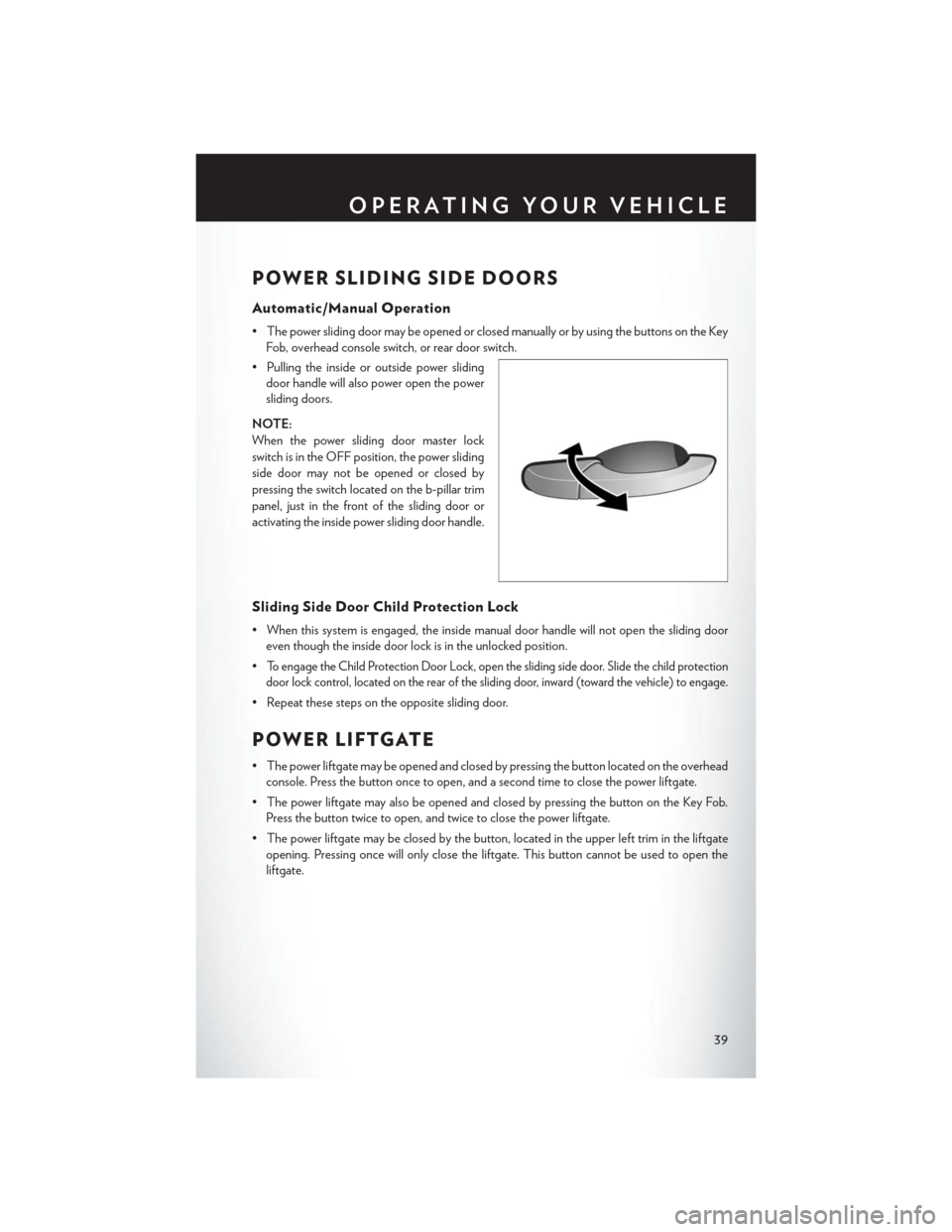
POWER SLIDING SIDE DOORS
Automatic/Manual Operation
• The power sliding door may be opened or closed manually or by using the buttons on the KeyFob, overhead console switch, or rear door switch.
• Pulling the inside or outside power sliding door handle will also power open the power
sliding doors.
NOTE:
When the power sliding door master lock
switch is in the OFF position, the power sliding
side door may not be opened or closed by
pressing the switch located on the b-pillar trim
panel, just in the front of the sliding door or
activating the inside power sliding door handle.
Sliding Side Door Child Protection Lock
• When this system is engaged, the inside manual door handle will not open the sliding door even though the inside door lock is in the unlocked position.
•
To engage the Child Protection Door Lock, open the sliding side door. Slide the child protection
door lock control, located on the rear of the sliding door, inward (toward the vehicle) to engage.
• Repeat these steps on the opposite sliding door.
POWER LIFTGATE
• The power liftgate may be opened and closed by pressing the button located on the overhead console. Press the button once to open, and a second time to close the power liftgate.
• The power liftgate may also be opened and closed by pressing the button on the Key Fob. Press the button twice to open, and twice to close the power liftgate.
• The power liftgate may be closed by the button, located in the upper left trim in the liftgate opening. Pressing once will only close the liftgate. This button cannot be used to open the
liftgate.
OPERATING YOUR VEHICLE
39
Page 89 of 140

WARNING!
• To Avoid Serious Injury or Death DO NOT:• use a three-prong adaptor
• insert any objects into the receptacles
• touch with wet hands
Close the lid when not in use. If this outlet is mishandled, it may cause an electric shock and
failure.
POWER OUTLETS
• Two 12 Volt (13 Amp) power outlets are located on the lower instrument panel,
below the open storage bin. The driver-side
power outlet is controlled by the ignition
switch and the passenger-side power outlet
is connected directly to the battery. The
driver-side power outlet will also operate a
conventional cigar lighter unit (if equipped
with an optional Smoker's Package).
• One outlet in the removable floor console (if equipped) shares a fuse with the lower
outlet in the instrument panel and is also
connected to the battery. Do not exceed a maximum power of 160 Watts (13 Amps) shared
between the lower panel outlet and the removable floor console outlet.
• On vehicles equipped with the Super Console the power outlets are located under the retractable cover. To access the power outlets push down on the cover and slide it toward the
instrument panel.
• The outlet in the rear quarter panel near the liftgate and the upper outlet in the instrument panel are both controlled by the ignition switch. Each of these outlets can support 160 Watts
(13 Amps). Do not exceed 160 Watts (13 Amps) for each of these outlets.
ELECTRONICS
87
Page 91 of 140

IN-FLOOR STORAGE – STOW'N GO®
Second Row Seat Storage Bins
• Storage bins are located in the floor in front of the second row seats that can be used when thesecond row seat is in the upright position. Pull up on the storage bin latch to open the cover.
Slide the storage bin locking mechanism to the "Lock" position to allow greater access to the
storage bin.
Cargo Area Storage
•The liftgate sill plate has a raised line with the statement “Load To This Line”. This line indicates
how far rearward cargo can be placed without interfering with liftgate closing.
WARNING!
In a collision, serious injury could result if the seat storage bin covers are not properly latched.
Do not drive the vehicle with the storage bin covers open. Keep the storage bin covers closed
and latched while the vehicle is in motion. Do not use a storage bin latch as a tie down.
ROOF LUGGAGE RACK
•The crossbars on your vehicle are delivered
stowed within the roof rack side rails. When
installed, the roof rack can hold a maximum of
150 lbs (68 kg) of evenly distributed weight.
Installing The Crossbars
• To install the crossbars, completely loosen the thumb screws at both ends and lift the
crossbar from its stowed position.
• Bend the pivot points at each end of the crossbar and slide the thumb screw down.
• Set the crossbars into position and tighten the thumb screws.
NOTE:
Make sure the directional arrow on the crossbar
aligns with the directional arrow on the side rail.
• Refer to the Owner's Manual on the DVD for further details.
UTILITY
89