eco button CHRYSLER TOWN AND COUNTRY 2015 5.G Owner's Guide
[x] Cancel search | Manufacturer: CHRYSLER, Model Year: 2015, Model line: TOWN AND COUNTRY, Model: CHRYSLER TOWN AND COUNTRY 2015 5.GPages: 164, PDF Size: 22.47 MB
Page 88 of 164
Operation Of The Touchscreen Radio/DVD Player/Blu-Ray Player
• To view a DVD push the OPEN/CLOSE button on the faceplate and insert the disc or insert
the disc into the optional DVD player. Playback will begin automatically after the DVD is
recognized by the disc drive. If playback does not begin automatically when the disc is inserted
into the DVD player push the PLAY button. If playback does not begin automatically after the
disc is inserted into the touchscreen radio follow these steps:
• Push the MENU button on the faceplate, then press the Rear VES™ button on the
touchscreen. If a chapter list appears on the right side of the screen, press the “HIDE LIST”
button on the touchscreen to display the Rear VES™ control screen.
• Touch the “1” button on the touchscreen to select an audio channel, then press the DISC
button on the touchscreen in the MEDIA column.
Operation Of The Remote Control
The remote control operates similarly to any DVD remote you may have used before and allows
the rear seat passengers to change stations, tracks, discs and audio/video modes.
The remote control is designed to control either channel by using the selector switch located on
the right side of the remote.
Connect the video game or other external media devices to the AUX jacks following the color
coding for the VES™ jacks.
•PushingthepowerbuttonwillturntheVES™systemON/OFF.
• Pushing the mode button causes the MODE SELECTION menu to appear on the VES™
screen. Use the remote control arrow buttons to scroll through the available modes, and then
push ENTER to select the desired mode.
Auxiliary Audio/Video Input Jacks
The AUX jacks are located on the drivers side rear trim panel behind the sliding door.
Connect the video game or other external media devices to the AUX jacks following the color
coding for the VES™ jacks.
Using either the touchscreen radio or remote control, select AUX from the REAR VES™
CONTROL or the MODE SELECTION screen.
Refer to the Uconnect® Multimedia – Video Entertainment System (VES™) section in the vehicle
Owner's Manual on the DVD for further details.
ELECTRONICS
86
Page 89 of 164
ELECTRONIC VEHICLE INFORMATION
CENTER (EVIC)
The EVIC features a driver interactive display that is located in the instrument cluster. Pushing
the controls on the left side of the steering wheel allows the driver to select vehicle information
and Personal Settings. For additional information, refer to “Programmable Features” located in
this guide.
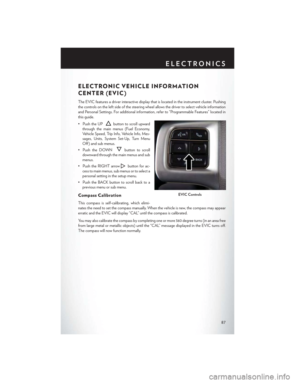
• Push the UPbutton to scroll upward
through the main menus (Fuel Economy,
Vehicle Speed, Trip Info, Vehicle Info, Mes-
sages, Units, System Set-Up, Turn Menu
Off ) and sub menus.
• Push the DOWNbutton to scroll
downward through the main menus and sub
menus.
• Push the RIGHT arrowbutton for ac-
cess to main menus, sub menus or to select a
personal setting in the setup menu.
•PushtheBACKbuttontoscrollbacktoa
previous menu or sub menu.
Compass Calibration
This compass is self-calibrating, which elimi-
nates the need to set the compass manually. When the vehicle is new, the compass may appear
erratic and the EVIC will display “CAL” until the compass is calibrated.
Yo u m a y a l s o c a l i b r a t e t h e c o m p a s s b y c o m p l e t i n g o n e o r m o r e 3 6 0 d e g r e e t u r n s ( i n a n a r e a f r e e
from large metal or metallic objects) until the “CAL” message displayed in the EVIC turns off.
The compass will now function normally.
EVIC Controls
ELECTRONICS
87
Page 90 of 164
PROGRAMMABLE FEATURES
Electronic Vehicle Information Center (EVIC ) — If Equipped
Personal Settings allows you to set and recall features when the transmission is in PARK. If the
transmission is out of PARK or the vehicle begins moving, a warning message SYSTEM SETUP
NOT AVAILABLE VEHICLE NOT IN PARK displays when you try to select “System Setup”
from the main menu.
The EVIC can be used to program the following Personal Settings. Push the RIGHT arrow
buttonuntil Personal Settings displays, then push the DOWN buttonto scroll through
the settings. Push the RIGHT arrow buttonto change the setting.
• Select Language• Key-Off Power Delay
•Nav-TurnByTurn•IlluminatedApproach
• Auto Lock Doors• Hill Start Assist
• Auto Unlock Doors• Flashers with Sliding Door
•RemoteUnlockSequence•CalibrateCompass
•RemoteStartComfortSys.•CompassVariance
• Horn with Remote Lock• Park Assist - If Equipped
• Flash Lamps With Lock• Automatic High Beams - If Equipped
• Headlamp Off Delay• Keyless Enter-N-Go - If Equipped
• Headlamps With Wipers• RKE Linked To Memory - If Equipped
Key Fob Programmable Features
The following features may also be programmed by using the Key Fob transmitter or the ignition
switch and driver's door lock switch.
NOTE:
Pushing the LOCK button while you are inside the vehicle will activate the Vehicle Security
Alarm. Opening a door with the Vehicle Security Alarm activated will cause the alarm to sound.
Push the UNLOCK button to deactivate the Vehicle Security Alarm.
Unlock On First Press
To u n l o c k e i t h e r t h e d r i v e r ' s s i d e , o r a l l d o o r s , o n t h e f i r s t p u s h o f t h e U N L O C K b u t t o n :
• Push and hold the LOCK button for at least four seconds, but no longer than 10 seconds.
Then, push and hold the UNLOCK button while still holding the LOCK button.
• Release both buttons at the same time.
Auto Unlock Doors On Exit
To h a v e a l l o f t h e v e h i c l e d o o r s u n l o c k w h e n a n y d o o r i s o p e n e d :
•Enteryourvehicleandcloseallthedoors,andfastenyourseatbelt.
•CycletheignitionswitchbetweentheLOCKandONpositionfourtimes,endinginthe
LOCK position (do not start the engine).
ELECTRONICS
88
Page 91 of 164
• Push the power door UNLOCK switch to unlock the doors. A single chime will indicate that
programming is complete.
Sound Horn With Lock
To turn the horn chirp on or off when the doors are locked:
• Push the LOCK button and PANIC button at the same time for at least four seconds, but no
longer than 10 seconds.
• Release both buttons at the same time.
Flashing Lights With Lock
The turn signal lights flash when the doors are locked, which can be turned on or off. To turn this
feature on or off:
• Push and hold the UNLOCK button and the LOCK button at the same time for at least four
seconds, but no longer than 10 seconds.
• Release both buttons at the same time.
UNIVERSAL GARAGE DOOR OPENER
(HomeLink®)
HomeLink® replaces up to three hand-held transmitters that operate devices such as garage door
openers, motorized gates, lighting or home security systems. The HomeLink® unit is powered by
your vehicles 12 Volt battery.
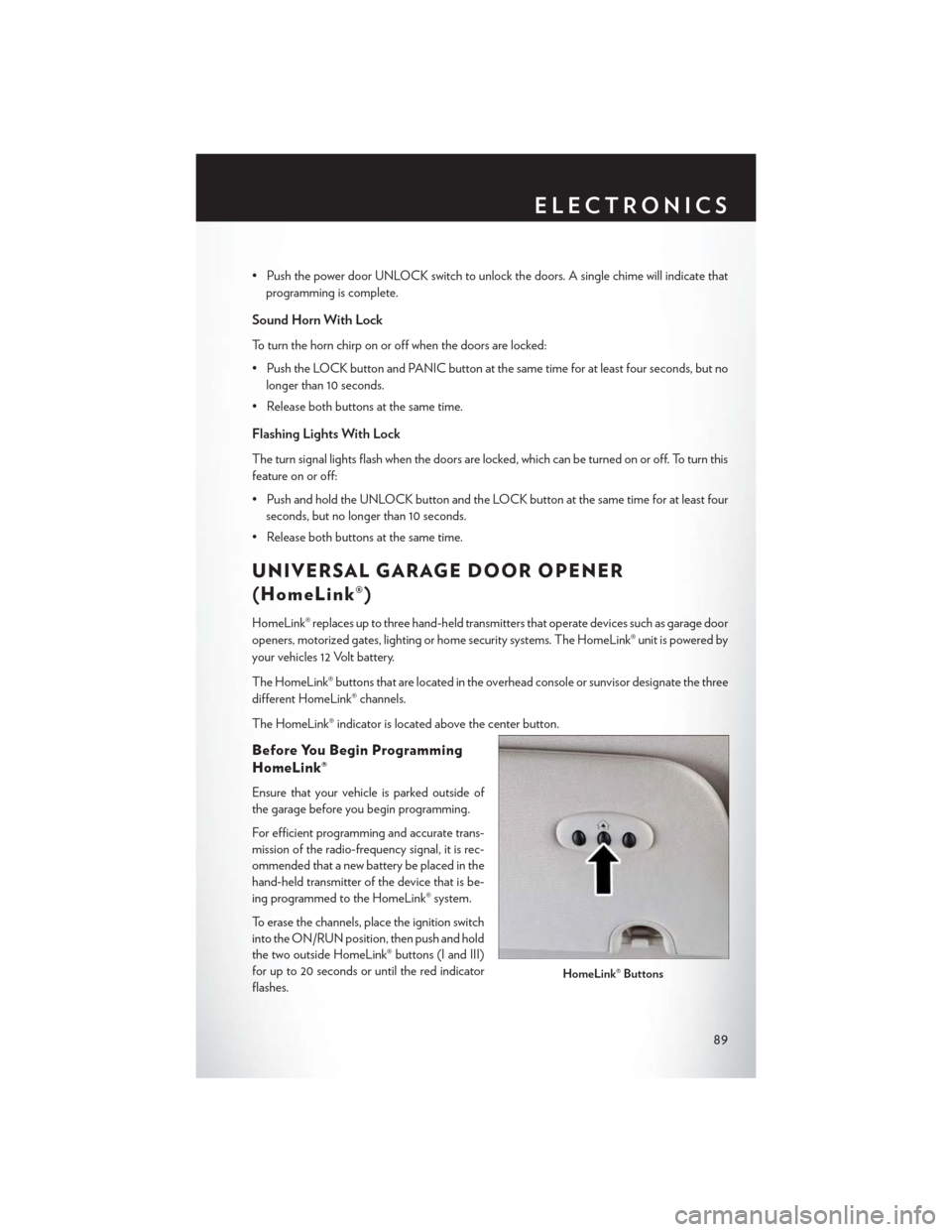
The HomeLink® buttons that are located in the overhead console or sunvisor designate the three
different HomeLink® channels.
The HomeLink® indicator is located above the center button.
Before You Begin Programming
HomeLink®
Ensure that your vehicle is parked outside of
the garage before you begin programming.
For efficient programming and accurate trans-
mission of the radio-frequency signal, it is rec-
ommended that a new battery be placed in the
hand-held transmitter of the device that is be-
ing programmed to the HomeLink® system.
To erase the channels, place the ignition switch
into the ON/RUN position, then push and hold
the two outside HomeLink® buttons (I and III)
for up to 20 seconds or until the red indicator
flashes.HomeLink® Buttons
ELECTRONICS
89
Page 92 of 164

NOTE:
Erasing all channels should only be performed when programming HomeLink® for the first time.
Do not erase channels when programming additional buttons.
If you have any problems, or require assistance, please call toll-free 1-800-355-3515 or, on the
Internet at HomeLink.com for information or assistance.
Programming A Rolling Code
NOTE:
For programming Garage Door Openers that were manufactured after 1995. These Garage
Door Openers can be identified by the “LEARN” or “TRAIN” button located where the hanging
antenna is attached to the Garage Door Opener. It is NOT the button that is normally used to
open and close the door. The name and color of the button may vary by manufacturer.
1. Place the ignition switch into the ON/RUN position.
2. Place the hand-held transmitter 1 to 3 inches (3 to 8 cm) away from the HomeLink® button you
wish to program while keeping the HomeLink® indicator light in view.
3. Push and hold the HomeLink® button you want to program while you push and hold the
hand-held transmitter button.
4. Continue to hold both buttons and observe the indicator light. The HomeLink® indicator will
flash slowly and then rapidly after HomeLink® has received the frequency signal from the
hand-held transmitter. Release both buttons after the indicator light changes from slow to
rapid.
5. At the garage door opener motor (in the garage), locate the “LEARN” or “TRAINING”
button. This can usually be found where the hanging antenna wire is attached to the garage
door opener motor. Firmly push and release the “LEARN” or “TRAINING” button.
NOTE:
Yo u h a v e 3 0 s e c o n d s i n w h i c h t o i n i t i a t e t h e n e x t s t e p a f t e r t h e L E A R N b u t t o n h a s b e e n p u s h e d .
6. Return to the vehicle and push the programmed HomeLink® button twice (holding the button
for two seconds each time). If the device is plugged in and activates, programming is
complete.
NOTE:
If the device does not activate, push the button a third time (for two seconds) to complete the
training.
7. To program the remaining two HomeLink® buttons, repeat each step for each remaining
button. DO NOT erase the channels.
ELECTRONICS
90
Page 104 of 164
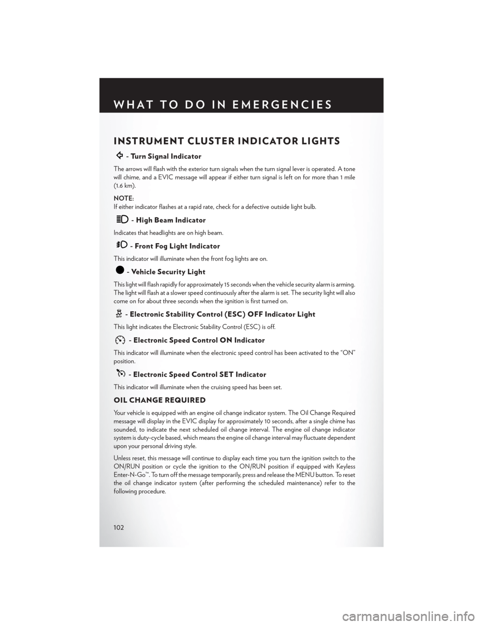
INSTRUMENT CLUSTER INDICATOR LIGHTS
-TurnSignalIndicator
The arrows will flash with the exterior turn signals when the turn signal lever is operated. A tone
will chime, and a EVIC message will appear if either turn signal is left on for more than 1 mile
(1.6 km).
NOTE:
If either indicator flashes at a rapid rate, check for a defective outside light bulb.
-HighBeamIndicator
Indicates that headlights are on high beam.
-FrontFogLightIndicator
This indicator will illuminate when the front fog lights are on.
-VehicleSecurityLight
This light will flash rapidly for approximately 15 seconds when the vehicle security alarm is arming.
The light will flash at a slower speed continuously after the alarm is set. The security light will also
come on for about three seconds when the ignition is first turned on.
-ElectronicStabilityControl(ESC)OFFIndicatorLight
This light indicates the Electronic Stability Control (ESC) is off.
-ElectronicSpeedControlONIndicator
This indicator will illuminate when the electronic speed control has been activated to the “ON”
position.
-ElectronicSpeedControlSETIndicator
This indicator will illuminate when the cruising speed has been set.
OIL CHANGE REQUIRED
Yo u r v e h i c l e i s e q u i p p e d w i t h a n e n g i n e o i l c h a n g e i n d i c a t o r s y s t e m . T h e O i l C h a n g e R e q u i r e d
message will display in the EVIC display for approximately 10 seconds, after a single chime has
sounded, to indicate the next scheduled oil change interval. The engine oil change indicator
system is duty-cycle based, which means the engine oil change interval may fluctuate dependent
upon your personal driving style.
Unless reset, this message will continue to display each time you turn the ignition switch to the
ON/RUN position or cycle the ignition to the ON/RUN position if equipped with Keyless
Enter-N-Go™. To turn off the message temporarily, press and release the MENU button. To reset
the oil change indicator system (after performing the scheduled maintenance) refer to the
following procedure.
WHAT TO DO IN EMERGENCIES
102
Page 105 of 164

Vehicles Equipped With Keyless Enter-N-Go™
1. Without pressing the brake pedal, push the ENGINE START/STOP button and cycle the
ignition to the ON/RUN position (do not start the engine.)
2. Fully depress the accelerator pedal, slowly, three times within 10 seconds.
3. Without pressing the brake pedal, push the ENGINE START/STOP button once to return
the ignition to the OFF/LOCK position.
Vehicles Not Equipped With Keyless Enter-N-Go™
1. Turn the ignition switch to the ON/RUN position (do not start the engine.)
2. Fully depress the accelerator pedal, slowly, three times within 10 seconds.
3. Turn the ignition switch to the OFF/LOCK position.
NOTE:
If the indicator message illuminates when you start the engine, the oil change indicator system did
not reset. If necessary, repeat these steps.
Resetting The Light After Servicing
Vehicles Equipped With Keyless Enter-N-Go™
1. Without pressing the brake pedal, push the ENGINE START/STOP button and cycle the
ignition to the ON/RUN position (do not start the engine.)
2. Fully depress the accelerator pedal, slowly, three times within 10 seconds.
3. Without pressing the brake pedal, push the ENGINE START/STOP button once to return
the ignition to the OFF/LOCK position.
Vehicles Not Equipped With Keyless Enter-N-Go™
1. Turn the ignition switch to the ON/RUN position (do not start the engine.)
2. Fully depress the accelerator pedal, slowly, three times within 10 seconds.
3. Turn the ignition switch to the OFF/LOCK position.
NOTE:
If the indicator message illuminates when you start the vehicle, the oil change indicator system did
not reset. If necessary, repeat this procedure.
WHAT TO DO IN EMERGENCIES
103
Page 107 of 164
Ti re S e r v i c e K i t S t o ra g e
•TheTireServiceKitisstowedbehindtherearleftsidetrimpanelintherearcargoarea.
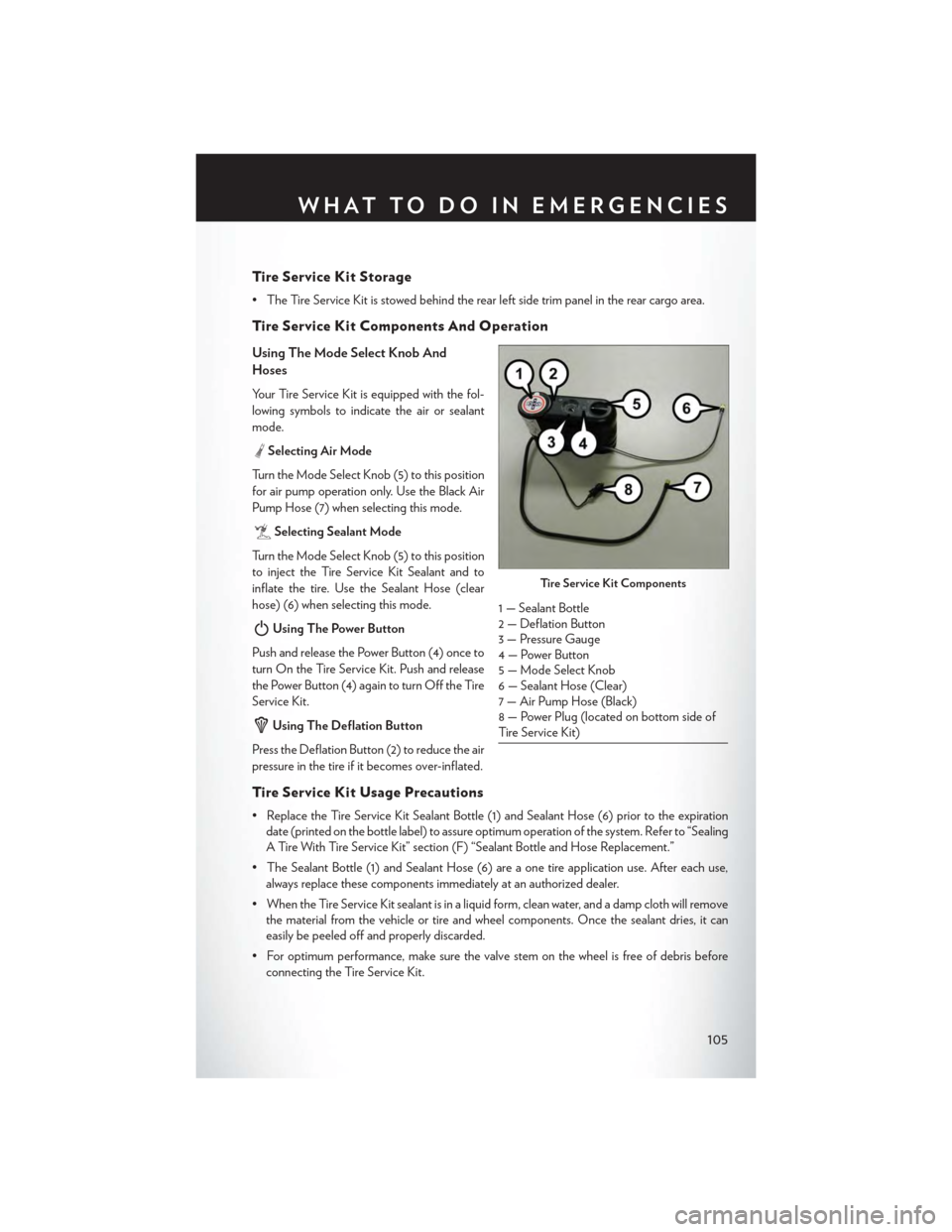
Ti re S e r v i c e K i t Co m p o n e n t s A n d O p e ra t i o n
Using The Mode Select Knob And
Hoses
Your Tire Service Kit is equipped with the fol-
lowing symbols to indicate the air or sealant
mode.
Selecting Air Mode
Tu r n t h e M o d e S e l e c t K n o b ( 5 ) t o t h i s p o s i t i o n
for air pump operation only. Use the Black Air
Pump Hose (7) when selecting this mode.
Selecting Sealant Mode
Tu r n t h e M o d e S e l e c t K n o b ( 5 ) t o t h i s p o s i t i o n
to inject the Tire Service Kit Sealant and to
inflate the tire. Use the Sealant Hose (clear
hose) (6) when selecting this mode.
Using The Power Button
Push and release the Power Button (4) once to
turn On the Tire Service Kit. Push and release
the Power Button (4) again to turn Off the Tire
Service Kit.
Using The Deflation Button
Press the Deflation Button (2) to reduce the air
pressure in the tire if it becomes over-inflated.
Ti re S e r v i c e K i t Us a g e Pre c a u t i o n s
• Replace the Tire Service Kit Sealant Bottle (1) and Sealant Hose (6) prior to the expiration
date (printed on the bottle label) to assure optimum operation of the system. Refer to “Sealing
A Tire With Tire Service Kit” section (F) “Sealant Bottle and Hose Replacement.”
• The Sealant Bottle (1) and Sealant Hose (6) are a one tire application use. After each use,
always replace these components immediately at an authorized dealer.
•WhentheTireServiceKitsealantisinaliquidform,cleanwater,andadampclothwillremove
the material from the vehicle or tire and wheel components. Once the sealant dries, it can
easily be peeled off and properly discarded.
•Foroptimumperformance,makesurethevalvestemonthewheelisfreeofdebrisbefore
connecting the Tire Service Kit.
Ti re S e r v i c e K i t Co m p o n e n t s
1 — Sealant Bottle2 — Deflation Button3 — Pressure Gauge4 — Power Button5—ModeSelectKnob6 — Sealant Hose (Clear)7 — Air Pump Hose (Black)8 — Power Plug (located on bottom side ofTire Service Kit)
WHAT TO DO IN EMERGENCIES
105
Page 109 of 164
If the sealant (white fluid) does not flow within0–10seconds through the Sealant Hose (6):
1. Press the Power Button (4) to turn Off the Tire Service Kit. Disconnect the Sealant Hose (6)
from the valve stem. Make sure the valve stem is free of debris. Reconnect the Sealant
Hose (6) to the valve stem. Check that the Mode Select Knob (5) is in the Sealant Mode
position and not Air Mode. Press the Power Button (4) to turn On the Tire Service Kit.
2. Connect the Power Plug (8) to a different 12 Volt power outlet in your vehicle or another
vehicle, if available. Make sure the engine is running before turning ON the Tire Service Kit.
3. The Sealant Bottle (1) may be empty due to previous use. Call for assistance.
NOTE:
If the Mode Select Knob (5) is on Air Mode and the pump is operating, air will dispense from the
Air Pump Hose (7) only, not the Sealant Hose (6).
If the sealant (white fluid) does flow through the Sealant Hose (6):
1. Continue to operate the pump until sealant is no longer flowing through the hose (typically
takes 30 - 70 seconds). As the sealant flows through the Sealant Hose (6), the Pressure Gauge
(3) can read as high as 70 psi (4.8 Bar). The Pressure Gauge (3) will decrease quickly from
approximately 70 psi (4.8 Bar) to the actual tire pressure when the Sealant Bottle (1) is empty.
2. The pump will start to inject air into the tire immediately after the Sealant Bottle (1) is empty.
Continue to operate the pump and inflate the tire to the pressure indicated on the tire pressure
label on the driver-side latch pillar (recommended pressure). Check the tire pressure by
looking at the Pressure Gauge (3).
If the tire does not inflate to at least 26 psi (1.8 Bar) pressure within 15 minutes:
The tire is too badly damaged. Do not attempt to drive the vehicle further. Call for assistance.
NOTE:
If the tire becomes over-inflated, press the Deflation Button to reduce the tire pressure to the
recommended inflation pressure before continuing.
If the tire inflates to the recommended pressure or is at least 26 psi (1.8 Bar) pressure within
15 minutes:
1. Press the Power Button (4) to turn off the Tire Service Kit.
2. Remove the Speed Limit sticker from the top of the Sealant Bottle (1) and place the sticker on
the instrument panel.
3. Immediately disconnect the Sealant Hose (6) from the valve stem, reinstall the cap on the
fitting at the end of the hose, and place the Tire Service Kit in the vehicle storage location.
Quickly proceed to (D) “Drive Vehicle.”
(D) Drive Vehicle:
Immediately after injecting sealant and inflating the tire, drive the vehicle 5 miles (8 km) or
10 minutes to ensure distribution of the Tire Service Kit Sealant within the tire. Do not exceed
55 mph (88 km/h).
WHAT TO DO IN EMERGENCIES
107
Page 110 of 164
(E) After Driving:
Pull over to a safe location. Refer to “Whenever You Stop to Use Tire Service Kit” before continuing.
1. Turn the Mode Select Knob (5) to the Air Mode position.
2. Uncoil the Air Pump Hose (7) (black in color) and screw the fitting at the end of hose (7) onto
the valve stem.
3. Uncoil the power plug and insert the plug into the vehicles 12 Volt power outlet.
4. Check the pressure in the tire by reading the Pressure Gauge (3).
If tire pressure is less than 19 psi (1.3 Bar), the tire is too badly damaged. Do not attempt to
drive the vehicle further. Call for assistance.
If the tire pressure is 19 psi (1.3 Bar) or higher:
1. Press the Power Button (4) to turn on Tire Service Kit and inflate the tire to the pressure
indicated on the tire and loading information label on the driver-side door opening.
2. Disconnect the Tire Service Kit from the valve stem, reinstall the cap on the valve stem and
unplug from 12 Volt outlet.
3. Place the Tire Service Kit in its proper storage area in the vehicle.
4. Have the tire inspected and repaired or replaced at the earliest opportunity at an authorized
dealer or tire service center.
5. Remove the Speed Limit sticker from the instrument panel after the tire has been repaired.
6. Replace the Sealant Bottle (1) and Sealant Hose (6) assembly at your authorized dealer as
soon as possible. Refer to “(F) Sealant Bottle and Hose Replacement.”
NOTE:
•Ifthetirebecomesover-inflated,presstheDeflationButtontoreducethetirepressuretothe
recommended inflation pressure before continuing.
• When having the tire serviced, advise the authorized dealer or service center that the tire has
been sealed using the Tire Service Kit.
(F) Sealant Bottle And Hose Replacement:
1. Uncoil the Sealant Hose (6) (clear in color).
2. Locate the round Sealant Bottle release button in the recessed area under the sealant bottle.
3. Press the Sealant Bottle release button. The Sealant Bottle (1) will pop up. Remove the bottle
and dispose of it accordingly.
4. Clean any remaining sealant from the Tire Service Kit housing.
5. Position the new Sealant Bottle (1) in the housing so that the Sealant Hose (6) aligns with the
hose slot in the front of the housing. Press the bottle into the housing. An audible click will be
heard indicating the bottle is locked into place.
WHAT TO DO IN EMERGENCIES
108