battery replacement CHRYSLER VOYAGER 1996 Service Manual
[x] Cancel search | Manufacturer: CHRYSLER, Model Year: 1996, Model line: VOYAGER, Model: CHRYSLER VOYAGER 1996Pages: 1938, PDF Size: 55.84 MB
Page 91 of 1938

normal. This may indicate:(1)Abnormal loss of
brake fluid in the master cylinder fluid reservoir
resulting from a leak in the hydraulic system.(2)
Brake shoe linings which have worn to a point
requiring replacement.
As the brake fluid drops below the minimum level,
the brake fluid level sensor closes to ground the
brake warning light circuit. This will turn on the red
brake warning light. At this time, master cylinder
fluid reservoir should be checked and filled to the full
mark with DOT 3 brake fluid.If brake fluid level
has dropped below the add line in the master
cylinder fluid reservoir, the entire brake
hydraulic system should be checked for evi-
dence of a leak.
STOP LAMP SWITCH
The stop lamp switch controls operation of the
vehicles stop lamps. Also, if the vehicle is equippedwith speed control, the stop lamp switch will deacti-
vate speed control when the brake pedal is
depressed.
The stop lamp switch controls operation of the
right and left tail, stop and turn signal lamp and
CHMSL lamp, by supplying battery current to these
lamps.
The stop lamp switch controls the lamp operation
by opening and closing the electrical circuit to the
stop lamps.
HUB/BEARING REAR WHEEL
The rear hub and bearing assembly used on this
vehicle is serviceable only as a complete assembly. No
attempt should be made to disassemble a rear hub
and bearing assembly in an effort to repair it.
The rear hub and bearing assembly is attached to
the rear axle using 4 mounting bolts that are remov-
able from the back of the rear hub/bearing.
DIAGNOSIS AND TESTING
BRAKE SYSTEM BASIC DIAGNOSIS GUIDE
SYMPTOMCHART 1
MISC.
COND.CHART 2
WARNING
LIGHTCHART 3
POWER
BRAKESCHART 4
BRAKE
NOISECHART 5
WHEEL
BRAKES
Brake Warning Light On X NO NO
Excessive Pedal Travel 6 X NO O
Pedal Goes To The Floor 6 X
Stop Light On Without Brakes 3
All Brakes Drag 5
Rear Brakes Drag 2 NO NO
Grabby Brakes O X
Spongy Brake Pedal X NO
Premature Rear Brake Lockup 4 NO NO O
Excessive Pedal Effort 1 O
Rough Engine Idle NO O
Brake Chatter (Rough) NO NO X
Surge During Braking NO NO X
Noise During Braking NO NO X
Rattle Or Clunking Noise NO NO X
Pedal Pulsates During Braking NO NO X
Pull To Right Or Left NO NO X
No: Not A Possible Cause X: Most Likely Cause O: Possible Cause
NSBRAKES 5 - 9
DESCRIPTION AND OPERATION (Continued)
Page 140 of 1938
INSTALL
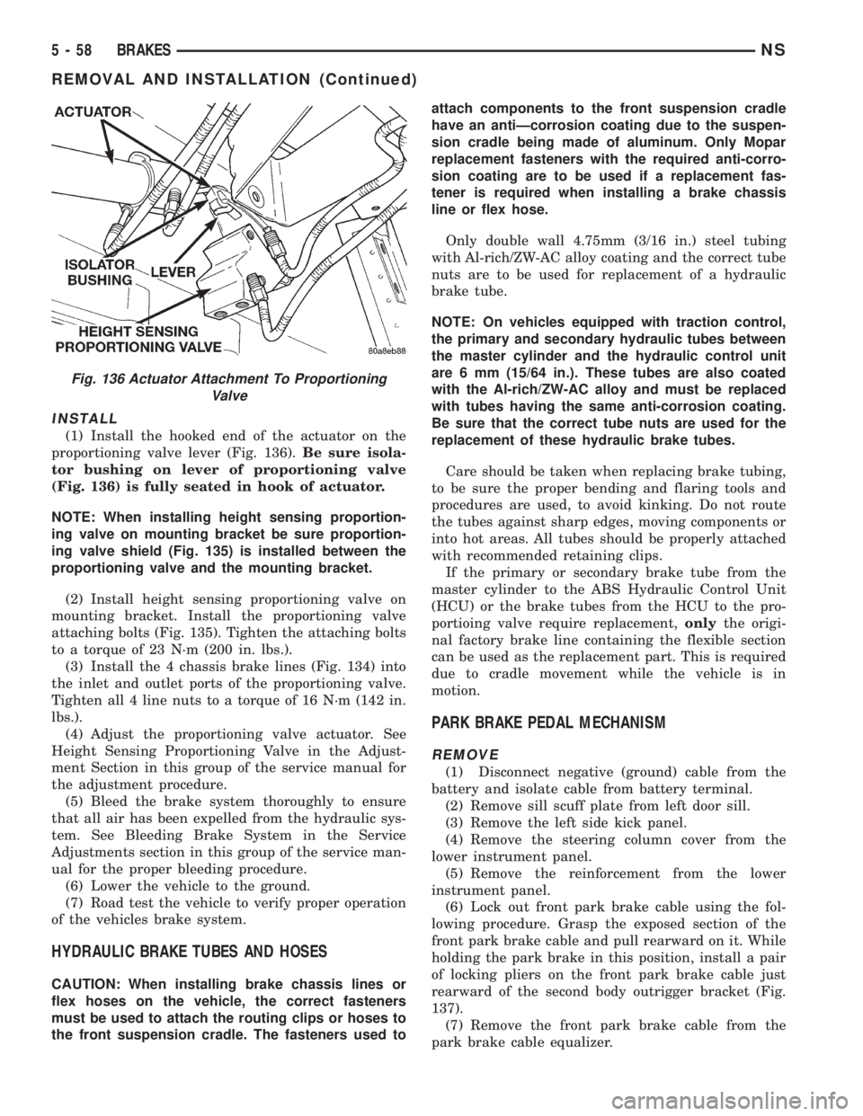
(1) Install the hooked end of the actuator on the
proportioning valve lever (Fig. 136).Be sure isola-
tor bushing on lever of proportioning valve
(Fig. 136) is fully seated in hook of actuator.
NOTE: When installing height sensing proportion-
ing valve on mounting bracket be sure proportion-
ing valve shield (Fig. 135) is installed between the
proportioning valve and the mounting bracket.
(2) Install height sensing proportioning valve on
mounting bracket. Install the proportioning valve
attaching bolts (Fig. 135). Tighten the attaching bolts
to a torque of 23 N´m (200 in. lbs.).
(3) Install the 4 chassis brake lines (Fig. 134) into
the inlet and outlet ports of the proportioning valve.
Tighten all 4 line nuts to a torque of 16 N´m (142 in.
lbs.).
(4) Adjust the proportioning valve actuator. See
Height Sensing Proportioning Valve in the Adjust-
ment Section in this group of the service manual for
the adjustment procedure.
(5) Bleed the brake system thoroughly to ensure
that all air has been expelled from the hydraulic sys-
tem. See Bleeding Brake System in the Service
Adjustments section in this group of the service man-
ual for the proper bleeding procedure.
(6) Lower the vehicle to the ground.
(7) Road test the vehicle to verify proper operation
of the vehicles brake system.
HYDRAULIC BRAKE TUBES AND HOSES
CAUTION: When installing brake chassis lines or
flex hoses on the vehicle, the correct fasteners
must be used to attach the routing clips or hoses to
the front suspension cradle. The fasteners used toattach components to the front suspension cradle
have an antiÐcorrosion coating due to the suspen-
sion cradle being made of aluminum. Only Mopar
replacement fasteners with the required anti-corro-
sion coating are to be used if a replacement fas-
tener is required when installing a brake chassis
line or flex hose.
Only double wall 4.75mm (3/16 in.) steel tubing
with Al-rich/ZW-AC alloy coating and the correct tube
nuts are to be used for replacement of a hydraulic
brake tube.
NOTE: On vehicles equipped with traction control,
the primary and secondary hydraulic tubes between
the master cylinder and the hydraulic control unit
are 6 mm (15/64 in.). These tubes are also coated
with the Al-rich/ZW-AC alloy and must be replaced
with tubes having the same anti-corrosion coating.
Be sure that the correct tube nuts are used for the
replacement of these hydraulic brake tubes.
Care should be taken when replacing brake tubing,
to be sure the proper bending and flaring tools and
procedures are used, to avoid kinking. Do not route
the tubes against sharp edges, moving components or
into hot areas. All tubes should be properly attached
with recommended retaining clips.
If the primary or secondary brake tube from the
master cylinder to the ABS Hydraulic Control Unit
(HCU) or the brake tubes from the HCU to the pro-
portioing valve require replacement,onlythe origi-
nal factory brake line containing the flexible section
can be used as the replacement part. This is required
due to cradle movement while the vehicle is in
motion.
PARK BRAKE PEDAL MECHANISM
REMOVE
(1) Disconnect negative (ground) cable from the
battery and isolate cable from battery terminal.
(2) Remove sill scuff plate from left door sill.
(3) Remove the left side kick panel.
(4) Remove the steering column cover from the
lower instrument panel.
(5) Remove the reinforcement from the lower
instrument panel.
(6) Lock out front park brake cable using the fol-
lowing procedure. Grasp the exposed section of the
front park brake cable and pull rearward on it. While
holding the park brake in this position, install a pair
of locking pliers on the front park brake cable just
rearward of the second body outrigger bracket (Fig.
137).
(7) Remove the front park brake cable from the
park brake cable equalizer.
Fig. 136 Actuator Attachment To Proportioning
Valve
5 - 58 BRAKESNS
REMOVAL AND INSTALLATION (Continued)
Page 182 of 1938
If the brake system is to be bled using pressurized
bleeding equipment, refer to Bleeding Brake System
in the Service Adjustments section at the beginning
of this group for proper equipment usage and proce-
dures.
(1) Assemble and install all brake system compo-
nents on the vehicle making sure all hydraulic fluid
lines are installed and properly torqued.
(2) Connect the DRB Diagnostics Tester to the
diagnostics connector. The Teves Mark 20 ABS diag-
nostic connector is located under the instrument
panel to the left of the steering column cover.
(3) Using the DRB, check to make sure the CAB
does not have any fault codes stored. If it does,
remove them using the DRB.
WARNING: WHEN BLEEDING THE BRAKE SYS-
TEM WEAR SAFETY GLASSES. A CLEAR BLEED
TUBE MUST BE ATTACHED TO THE BLEEDER
SCREWS AND SUBMERGED IN A CLEAR CON-
TAINER FILLED PART WAY WITH CLEAN BRAKE
FLUID. DIRECT THE FLOW OF BRAKE FLUID AWAY
FROM THE PAINTED SURFACES OF THE VEHICLE.
BRAKE FLUID AT HIGH PRESSURE MAY COME
OUT OF THE BLEEDER SCREWS WHEN OPENED.
(4) Bleed the base brake system using the stan-
dard pressure or manual bleeding procedure as out-
lined in the Service Adjustments section of this
service manual.
(5) Using the DRB, go to the9Bleed ABS9routine.
Apply the brake pedal firmly and initiate the9Bleed
ABS9cycle one time. Release the brake pedal.
(6) Bleed the base brake system again, as in step
Step 4 above.
(7) Repeat steps Step 5 and Step 6 above until
brake fluid flows clear and is free of any air bubbles.
Check brake fluid level in reservoir periodically to
prevent reservoir from running low on brake fluid.
(8) Test drive the vehicle to be sure brakes are
operating correctly and that brake pedal is solid.
REMOVAL AND INSTALLATION
ABS GENERAL SERVICE PRECAUTIONS
CAUTION: Review this entire section prior to per-
forming any mechanical work on a vehicle equipped
with the ITT Tevis Mark 20 ABS brake system. This
section contains information on precautions per-
taining to potential component damage, vehicle
damage and personal injury which could result
when servicing an ABS equipped vehicle.
CAUTION: Only the recommended jacking or hoist-
ing positions for this vehicle are to be used when-ever it is necessary to lift a vehicle. Failure to raise
a vehicle from the recommended locations could
result in lifting a vehicle by the hydraulic control
unit mounting bracket. Lifting a vehicle by the
hydraulic control unit mounting bracket will result
in damage to the mounting bracket and the hydrau-
lic control unit.
CAUTION: Certain components of the ABS System
are not intended to be serviced individually.
Attempting to remove or disconnect certain system
components may result in improper system opera-
tion. Only those components with approved
removal and installation procedures in this manual
should be serviced.
CAUTION: Brake fluid will damage painted sur-
faces. If brake fluid is spilled on any painted sur-
faces, wash off with water immediately.
CAUTION: When performing any service procedure
on a vehicle equipped with ABS do not apply a 12
volt power source to the ground circuit of the pump
motor in the CAB. Doing this will damage the pump
motor and will require replacement of the HCU.
The following are general cautions which should be
observed when servicing the ABS system and/or
other vehicle systems. Failure to observe these pre-
cautions may result in ABS System component dam-
age.
If welding work is to be performed on the vehicle,
using an electric arc welder, the CAB connector
should be disconnected during the welding operation.
The CAB 25 way connector connector should never
be connected or disconnected with the ignition switch
in the ON position.
Many components of the ABS System are not ser-
viceable and must be replaced as an assembly. Do not
disassemble any component which is not designed to
be serviced.
HYDRAULIC CONTROL UNIT
REMOVE
(1) Disconnect the negative (ground) cable from
the battery and isolate cable.
(2) Using a brake pedal depressor, move and lock
the brake pedal to a position past the first inch of
pedal travel.This will prevent brake fluid from
draining out of the master cylinder when the
brake tubes are removed from the HCU.
(3) Raise vehicle. Vehicle is to be raised and sup-
ported on jackstands or on a frame contact type
5 - 100 BRAKESNS
SERVICE PROCEDURES (Continued)
Page 184 of 1938
INSTALL
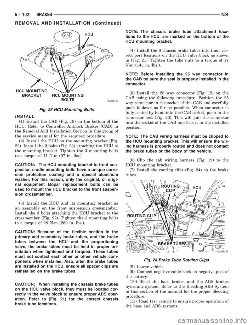
(1) Install the CAB (Fig. 19) on the bottom of the
HCU. Refer to Controller Antilock Brakes (CAB) in
the Removal And Installation Section in this group of
the service manual for the required procedure.
(2) Install the HCU on the mounting bracket (Fig.
23). Install the 3 bolts (Fig. 23) attaching the HCU to
the mounting bracket. Tighten the 3 mounting bolts
to a torque of 11 N´m (97 in. lbs.).
CAUTION: The HCU mounting bracket to front sus-
pension cradle mounting bolts have a unique corro-
sion protection coating and a special aluminum
washer. For this reason, only the original, or origi-
nal equipment Mopar replacement bolts can be
used to mount the HCU bracket to the front suspen-
sion crossmember.
(3) Install the HCU and its mounting bracket as
an assembly on the front suspension crossmember.
Install the 3 bolts attaching the HCU bracket to the
crossmember (Fig. 22). Tighten the 3 mounting bolts
to a torque of 28 N´m (250 in. lbs.).
CAUTION: Because of the flexible section in the
primary and secondary brake tubes, and the brake
tubes between the HCU and the proportioning
valve, the brake tubes must be held in proper ori-
entation when tightened and torqued. These tubes
must not contact each other or other vehicle com-
ponents when installed. Also, after the brake tubes
are installed on the HCU, ensure all spacer clips are
reinstalled on the brake tubes.
CAUTION: When installing the chassis brake tubes
on the HCU valve block, they must be located cor-
rectly in the valve block to ensure proper ABS oper-
ation. Refer to (Fig. 21) for the correct chassis
brake tube locations.NOTE: The chassis brake tube attachment loca-
tions to the HCU, are marked on the bottom of the
HCU mounting bracket.
(4) Install the 6 chassis brake tubes into their cor-
rect port locations on the HCU valve block as shown
in (Fig. 21). Tighten the tube nuts to a torque of 17
N´m (145 in. lbs.).
NOTE: Before installing the 25 way connector in
the CAB be sure the seal is properly installed in the
connector.
(5) Install the 25 way connector (Fig. 19) on the
CAB using the following procedure. Position the 25
way connector in the socket of the CAB and carefully
push it down as far as possible. When connector is
fully seated by hand into the CAB socket, push in the
connector lock (Fig. 20). This will pull the connector
into the socket of the CAB and lock it in the installed
position.
NOTE: The CAB wiring harness must be clipped to
the HCU mounting bracket. This will ensure the wir-
ing harness is properly routed and does not contact
the brake tubes or the body of the vehicle.
(6) Clip the cab wiring harness (Fig. 19) to the
HCU mounting bracket.
(7) Install the routing clips (Fig. 24) on the brake
tubes.
(8) Lower vehicle.
(9) Connect negative cable back on negative post of
the battery.
(10) Bleed the base brakes and the ABS brakes
hydraulic system. Refer to the Bleeding ABS System
in this section of the manual for the proper bleeding
procedure.
(11) Road test vehicle to ensure proper operation of
the base and ABS systems.
Fig. 23 HCU Mounting Bolts
Fig. 24 Brake Tube Routing Clips
5 - 102 BRAKESNS
REMOVAL AND INSTALLATION (Continued)
Page 288 of 1938

GENERATOR
The generator is belt-driven by the engine. It is
serviced only as a complete assembly. If the genera-
tor fails for any reason, the entire assembly must be
replaced.
As the energized rotor begins to rotate within the
generator, the spinning magnetic field induces a cur-
rent into the windings of the stator coil. Once the
generator begins producing sufficient current, it also
provides the current needed to energize the rotor.
The Y type stator winding connections deliver the
induced AC current to 3 positive and 3 negative
diodes for rectification. From the diodes, rectified DC
current is delivered to the vehicle electrical system
through the generator, battery, and ground terminals.
Noise emitting from the generator may be caused
by:
²Worn, loose or defective bearings
²Loose or defective drive pulley
²Incorrect, worn, damaged or misadjusted drive
belt
²Loose mounting bolts
²Misaligned drive pulley
²Defective stator or diode
BATTERY TEMPERATURE SENSOR
The temperature sensor, in the PCM, is used to
determine the battery temperature. This temperature
data, along with data from monitored line voltage, is
used by the PCM to vary the battery charging rate.
System voltage will be higher at colder temperatures
and is gradually reduced at warmer temperatures.
ELECTRONIC VOLTAGE REGULATOR
The Electronic Voltage Regulator (EVR) is not a
separate component. It is actually a voltage regulat-
ing circuit located within the Powertrain Control
Module (PCM). The EVR is not serviced separately. If
replacement is necessary, the PCM must be replaced.
Operation:The amount of DC current produced
by the generator is controlled by EVR circuitry con-
tained within the PCM. This circuitry is connected in
series with the generators second rotor field terminal
and its ground.
Voltage is regulated by cycling the ground path to
control the strength of the rotor magnetic field. The
EVR circuitry monitors system line voltage and bat-
tery temperature (refer to Battery Temperature Sen-
sor for more information). It then compensates and
regulates generator current output accordingly. Also
refer to Charging System Operation for additional
information.
DIAGNOSIS AND TESTING
CHARGING SYSTEM
When the ignition switch is turned to the ON posi-
tion, battery potential will register on the voltmeter.
During engine cranking a lower voltage will appear
on the meter. With the engine running, a voltage
reading higher than the first reading (ignition in ON)
should register.
The following are possible symptoms of a charging
system fault:
²The voltmeter does not operate properly
²An undercharged or overcharged battery condi-
tion occurs.
Remember that an undercharged battery is often
caused by:
²Accessories being left on with the engine not
running
²A faulty or improperly adjusted switch that
allows a lamp to stay on. See Ignition-Off Draw Test
in Group 8A, Battery for more information.
The following procedures may be used to correct a
problem diagnosed as a charging system fault.
INSPECTION
(1) Inspect condition of battery cable terminals,
battery posts, connections at engine block, starter
solenoid and relay. They should be clean and tight.
Repair as required.
(2) Inspect all fuses in the fuseblock module and
Power Distribution Center (PDC) for tightness in
receptacles. They should be properly installed and
tight. Repair or replace as required.
(3) Inspect the electrolyte level in the battery.
Replace battery if electrolyte level is low.
(4) Inspect generator mounting bolts for tightness.
Replace or tighten bolts if required. Refer to the Gen-
erator Removal/Installation section of this group for
torque specifications.
(5) Inspect generator drive belt condition and ten-
sion. Tighten or replace belt as required. Refer to
Belt Tension Specifications in Group 7, Cooling Sys-
tem.
(6) Inspect automatic belt tensioner (if equipped).
Refer to Group 7, Cooling System for information.
(7) Inspect connections at generator field, battery
output, and ground terminals. Also check ground con-
nection at engine. They should all be clean and tight.
Repair as required.
8C - 2 CHARGING SYSTEMNS
DESCRIPTION AND OPERATION (Continued)
Page 425 of 1938
INSTALLATION
Transfer speed control cable to replacement speed
control servo. Reverse the preceding operation.
SPEED CONTROL SWITCHES
REMOVAL
(1) Release hood latch and open hood.
(2) Disconnect battery negative cable.
(3) Remove airbag/horn pad from steering wheel,
refer to Group 8M, Restraint Systems for proper pro-
cedures.
(4) Disconnect wire connector from horn switch,
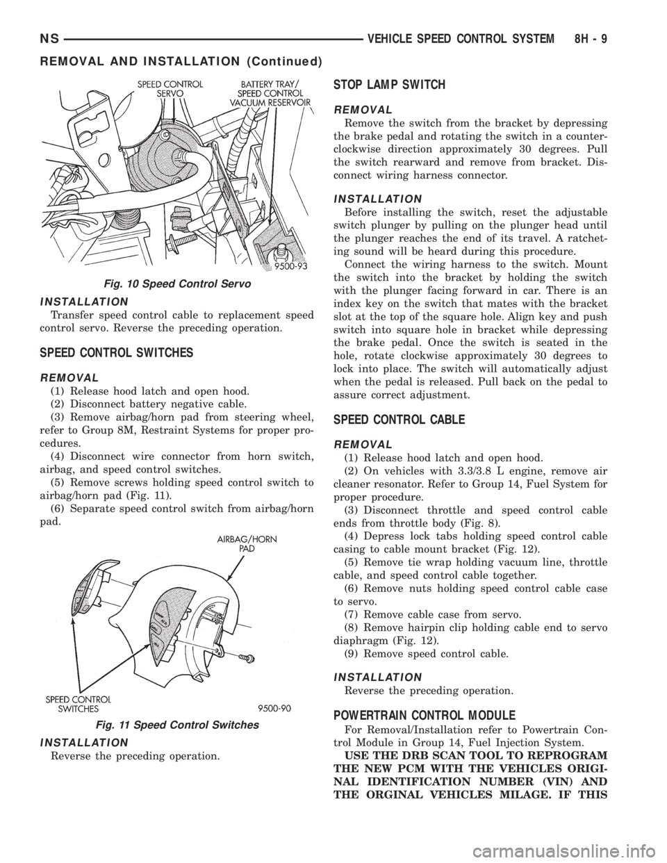
airbag, and speed control switches.
(5) Remove screws holding speed control switch to
airbag/horn pad (Fig. 11).
(6) Separate speed control switch from airbag/horn
pad.
INSTALLATION
Reverse the preceding operation.
STOP LAMP SWITCH
REMOVAL
Remove the switch from the bracket by depressing
the brake pedal and rotating the switch in a counter-
clockwise direction approximately 30 degrees. Pull
the switch rearward and remove from bracket. Dis-
connect wiring harness connector.
INSTALLATION
Before installing the switch, reset the adjustable
switch plunger by pulling on the plunger head until
the plunger reaches the end of its travel. A ratchet-
ing sound will be heard during this procedure.
Connect the wiring harness to the switch. Mount
the switch into the bracket by holding the switch
with the plunger facing forward in car. There is an
index key on the switch that mates with the bracket
slot at the top of the square hole. Align key and push
switch into square hole in bracket while depressing
the brake pedal. Once the switch is seated in the
hole, rotate clockwise approximately 30 degrees to
lock into place. The switch will automatically adjust
when the pedal is released. Pull back on the pedal to
assure correct adjustment.
SPEED CONTROL CABLE
REMOVAL
(1) Release hood latch and open hood.
(2) On vehicles with 3.3/3.8 L engine, remove air
cleaner resonator. Refer to Group 14, Fuel System for
proper procedure.
(3) Disconnect throttle and speed control cable
ends from throttle body (Fig. 8).
(4) Depress lock tabs holding speed control cable
casing to cable mount bracket (Fig. 12).
(5) Remove tie wrap holding vacuum line, throttle
cable, and speed control cable together.
(6) Remove nuts holding speed control cable case
to servo.
(7) Remove cable case from servo.
(8) Remove hairpin clip holding cable end to servo
diaphragm (Fig. 12).
(9) Remove speed control cable.
INSTALLATION
Reverse the preceding operation.
POWERTRAIN CONTROL MODULE
For Removal/Installation refer to Powertrain Con-
trol Module in Group 14, Fuel Injection System.
USE THE DRB SCAN TOOL TO REPROGRAM
THE NEW PCM WITH THE VEHICLES ORIGI-
NAL IDENTIFICATION NUMBER (VIN) AND
THE ORGINAL VEHICLES MILAGE. IF THIS
Fig. 10 Speed Control Servo
Fig. 11 Speed Control Switches
NSVEHICLE SPEED CONTROL SYSTEM 8H - 9
REMOVAL AND INSTALLATION (Continued)
Page 497 of 1938

RESTRAINT SYSTEM
CONTENTS
page page
GENERAL INFORMATION
WARNINGS AND PRECAUTIONS............ 1
DESCRIPTION AND OPERATION
AIRBAG CONTROL MODULE (ACM)......... 1
CLOCKSPRING.......................... 2
DRIVER AND PASSENGER
AIRBAG MODULES..................... 2
DIAGNOSIS AND TESTING
AIRBAG SYSTEM TEST................... 2
SERVICE PROCEDURES
CLEANUP PROCEDURE................... 3HANDLING AIRBAG MODULE.............. 3
REMOVAL AND INSTALLATION
AIRBAG CONTROL MODULE............... 3
CLOCKSPRING.......................... 5
DRIVER AIRBAG MODULE................. 5
PASSENGER AIRBAG..................... 6
ADJUSTMENTS
CLOCKSPRING CENTERING PROCEDURE..... 7
GENERAL INFORMATION
WARNINGS AND PRECAUTIONS
WARNING: THIS SYSTEM IS A SENSITIVE, COM-
PLEX ELECTRO±MECHANICAL UNIT. DISCONNECT
AND ISOLATE THE BATTERY NEGATIVE CABLE
BEFORE BEGINNING AIRBAG SYSTEM COMPO-
NENT REMOVAL OR INSTALLATION PROCEDURES.
THIS WILL DISABLE THE AIRBAG SYSTEM. FAIL-
URE TO DISCONNECT THE BATTERY COULD
RESULT IN ACCIDENTAL AIRBAG DEPLOYMENT
AND POSSIBLE PERSONAL INJURY.
ALLOW SYSTEM CAPACITOR TO DISCHARGE
FOR TWO MINUTES BEFORE REMOVING AIRBAG
COMPONENTS.
DO NOT PLACE AN INTACT UNDEPLOYED AIR-
BAG FACE DOWN ON A SOLID SURFACE, THE AIR-
BAG WILL PROPEL INTO THE AIR IF
ACCIDENTALLY DEPLOYED AND COULD RESULT
IN PERSONAL INJURY. WHEN CARRYING OR HAN-
DLING AN UNDEPLOYED AIRBAG MODULE, THE
TRIM SIDE OF THE AIRBAG SHOULD BE POINTING
AWAY FROM THE BODY TO MINIMIZE POSSIBILITY
OF INJURY IF ACCIDENTAL DEPLOYMENT
OCCURS.
REPLACE AIRBAG SYSTEM COMPONENTS WITH
MOPARTREPLACEMENT PARTS. SUBSTITUTE
PARTS MAY APPEAR INTERCHANGEABLE, BUT
INTERNAL DIFFERENCES MAY RESULT IN INFE-
RIOR OCCUPANT PROTECTION.
WEAR SAFETY GLASSES, RUBBER GLOVES,
AND LONG SLEEVED CLOTHING WHEN CLEANING
POWDER RESIDUE FROM VEHICLE AFTER AIRBAG
DEPLOYMENT. SODIUM HYDROXIDE POWDERRESIDUE EMITTED FROM A DEPLOYED AIRBAG
CAN CAUSE SKIN IRRITATION. FLUSH AFFECTED
AREA WITH COOL WATER IF IRRITATION IS EXPE-
RIENCED. IF NASAL OR THROAT IRRITATION IS
EXPERIENCED, EXIT THE VEHICLE FOR FRESH AIR
UNTIL THE IRRITATION CEASES. IF IRRITATION
CONTINUES, SEE A PHYSICIAN.
DO NOT USE A REPLACEMENT AIRBAG THAT IS
NOT IN THE ORIGINAL PACKAGING, IMPROPER
DEPLOYMENT AND PERSONAL INJURY CAN
RESULT.
THE FACTORY INSTALLED FASTENERS,
SCREWS AND BOLTS USED TO FASTEN AIRBAG
COMPONENTS HAVE A SPECIAL COATING AND
ARE SPECIFICALLY DESIGNED FOR THE AIRBAG
SYSTEM. DO NOT USE SUBSTITUTE FASTENERS,
USE ONLY ORIGINAL EQUIPMENT FASTENERS
LISTED IN THE PARTS CATALOG WHEN FASTENER
REPLACEMENT IS REQUIRED.
NOTE: Airbags should be stored in a cool dry loca-
tion away from excessive heat and static electrical
activity with the fabric airbag facing UP, or a prema-
ture deployment can result.
If the Driver/Passenger Airbag Module is defective
and not deployed, refer to Chrysler Corporation cur-
rent return list for proper handling procedures.
DESCRIPTION AND OPERATION
AIRBAG CONTROL MODULE (ACM)
The Airbag Control Module (ACM) contains the
impact sensor and energy reserve capacitor. The
NSRESTRAINT SYSTEM 8M - 1
Page 527 of 1938
If motor grunts and does not move, verify that reg-
ulator is not binding.
WIRING VOLTAGE TEST
The following wiring test determines whether or
not voltage is continuous through the body harness
to switch.
(1) Remove the master power window switch and
bezel assembly from the driver door. Refer to Group
23, Body for proper procedures.
(2) Disconnect wire connector from back of power
window switch.
(3) Switch ignition ON position.
(4) Connect the clip end of a 12 volt test light to
Pin 13 in door harness connector at the window
switch. Touch the test light probe to Pin 9 and then
to Pin 11.
²If the test light illuminates, the wiring circuit
between the battery and switch is OK.
²If light does not illuminate, check the 40 amp
fuse in the Power Distribution Center or for a broken
wire.
²The power window motors are protected with
Positive Temperature Coefficient (PTC) device that
prevents motor burn out. Check Junction Block.
²Refer to Group 8W, Wiring Diagrams for circuit
information and component locations.
REMOVAL AND INSTALLATION
POWER VENT WINDOW MOTOR
REMOVAL
(1) Disconnect battery negative cable.
(2) Remove D-pillar trim panel.
(3) Disconnect wire connector from power vent
motor.
(4) Remove nut holding crank to vent glass.
(5) Remove bolts holding power vent motor to
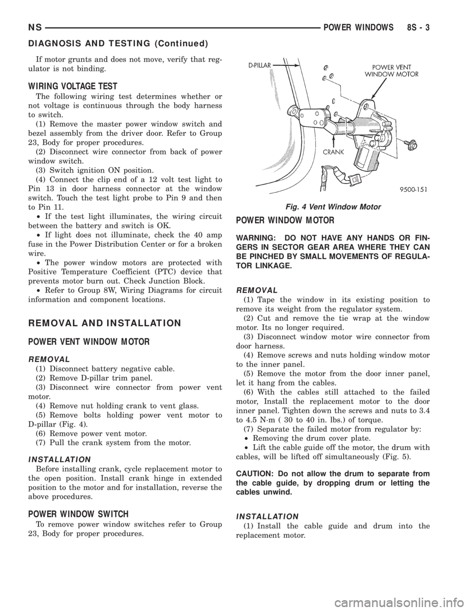
D-pillar (Fig. 4).
(6) Remove power vent motor.
(7) Pull the crank system from the motor.
INSTALLATION
Before installing crank, cycle replacement motor to
the open position. Install crank hinge in extended
position to the motor and for installation, reverse the
above procedures.
POWER WINDOW SWITCH
To remove power window switches refer to Group
23, Body for proper procedures.
POWER WINDOW MOTOR
WARNING: DO NOT HAVE ANY HANDS OR FIN-
GERS IN SECTOR GEAR AREA WHERE THEY CAN
BE PINCHED BY SMALL MOVEMENTS OF REGULA-
TOR LINKAGE.
REMOVAL
(1) Tape the window in its existing position to
remove its weight from the regulator system.
(2) Cut and remove the tie wrap at the window
motor. Its no longer required.
(3) Disconnect window motor wire connector from
door harness.
(4) Remove screws and nuts holding window motor
to the inner panel.
(5) Remove the motor from the door inner panel,
let it hang from the cables.
(6) With the cables still attached to the failed
motor, Install the replacement motor to the door
inner panel. Tighten down the screws and nuts to 3.4
to 4.5 N´m ( 30 to 40 in. lbs.) of torque.
(7) Separate the failed motor from regulator by:
²Removing the drum cover plate.
²Lift the cable guide off the motor, the drum with
cables, will be lifted off simultaneously (Fig. 5).
CAUTION: Do not allow the drum to separate from
the cable guide, by dropping drum or letting the
cables unwind.
INSTALLATION
(1) Install the cable guide and drum into the
replacement motor.
Fig. 4 Vent Window Motor
NSPOWER WINDOWS 8S - 3
DIAGNOSIS AND TESTING (Continued)
Page 573 of 1938
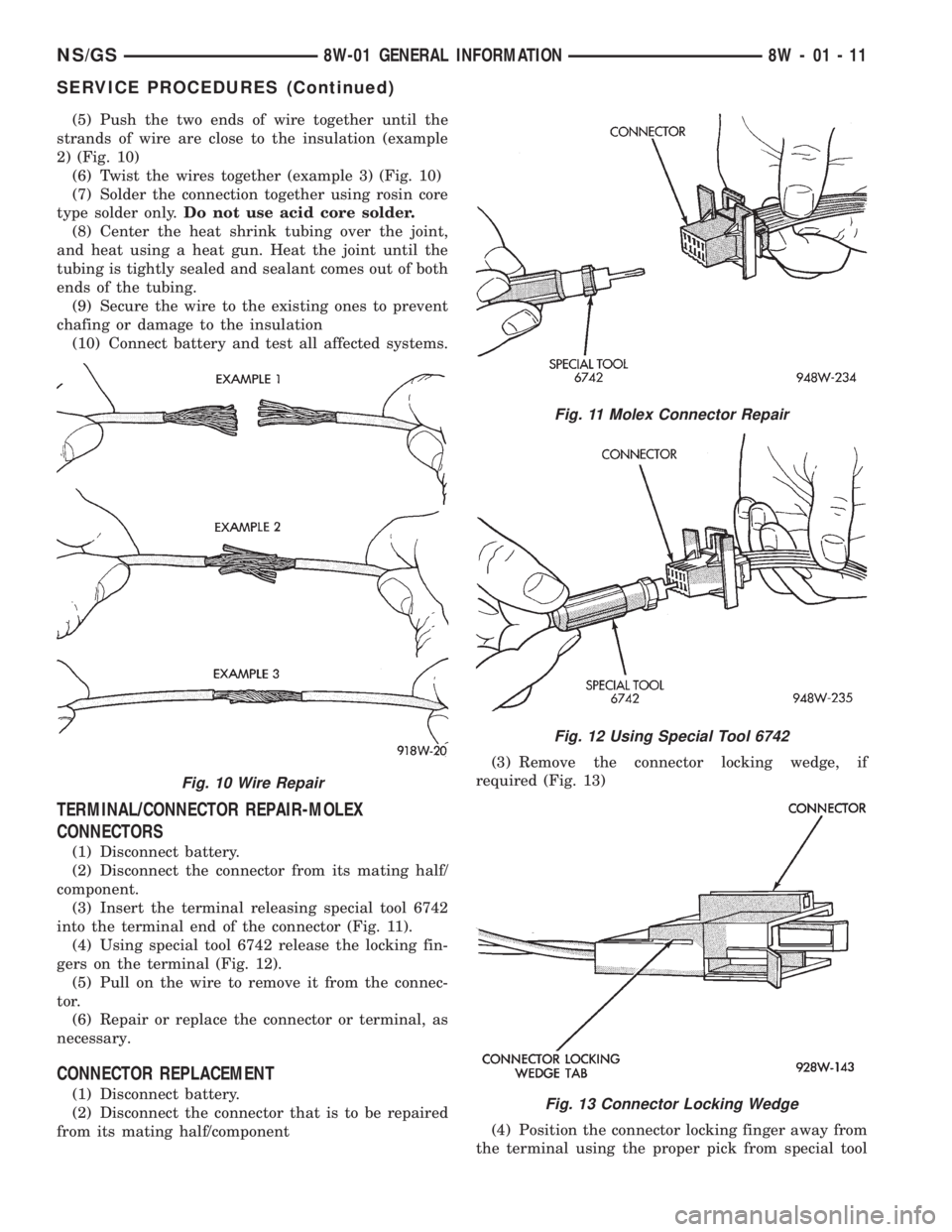
(5) Push the two ends of wire together until the
strands of wire are close to the insulation (example
2) (Fig. 10)
(6) Twist the wires together (example 3) (Fig. 10)
(7) Solder the connection together using rosin core
type solder only.Do not use acid core solder.
(8) Center the heat shrink tubing over the joint,
and heat using a heat gun. Heat the joint until the
tubing is tightly sealed and sealant comes out of both
ends of the tubing.
(9) Secure the wire to the existing ones to prevent
chafing or damage to the insulation
(10) Connect battery and test all affected systems.
TERMINAL/CONNECTOR REPAIR-MOLEX
CONNECTORS
(1) Disconnect battery.
(2) Disconnect the connector from its mating half/
component.
(3) Insert the terminal releasing special tool 6742
into the terminal end of the connector (Fig. 11).
(4) Using special tool 6742 release the locking fin-
gers on the terminal (Fig. 12).
(5) Pull on the wire to remove it from the connec-
tor.
(6) Repair or replace the connector or terminal, as
necessary.
CONNECTOR REPLACEMENT
(1) Disconnect battery.
(2) Disconnect the connector that is to be repaired
from its mating half/component(3) Remove the connector locking wedge, if
required (Fig. 13)
(4) Position the connector locking finger away from
the terminal using the proper pick from special tool
Fig. 10 Wire Repair
Fig. 11 Molex Connector Repair
Fig. 12 Using Special Tool 6742
Fig. 13 Connector Locking Wedge
NS/GS8W-01 GENERAL INFORMATION 8W - 01 - 11
SERVICE PROCEDURES (Continued)
Page 574 of 1938
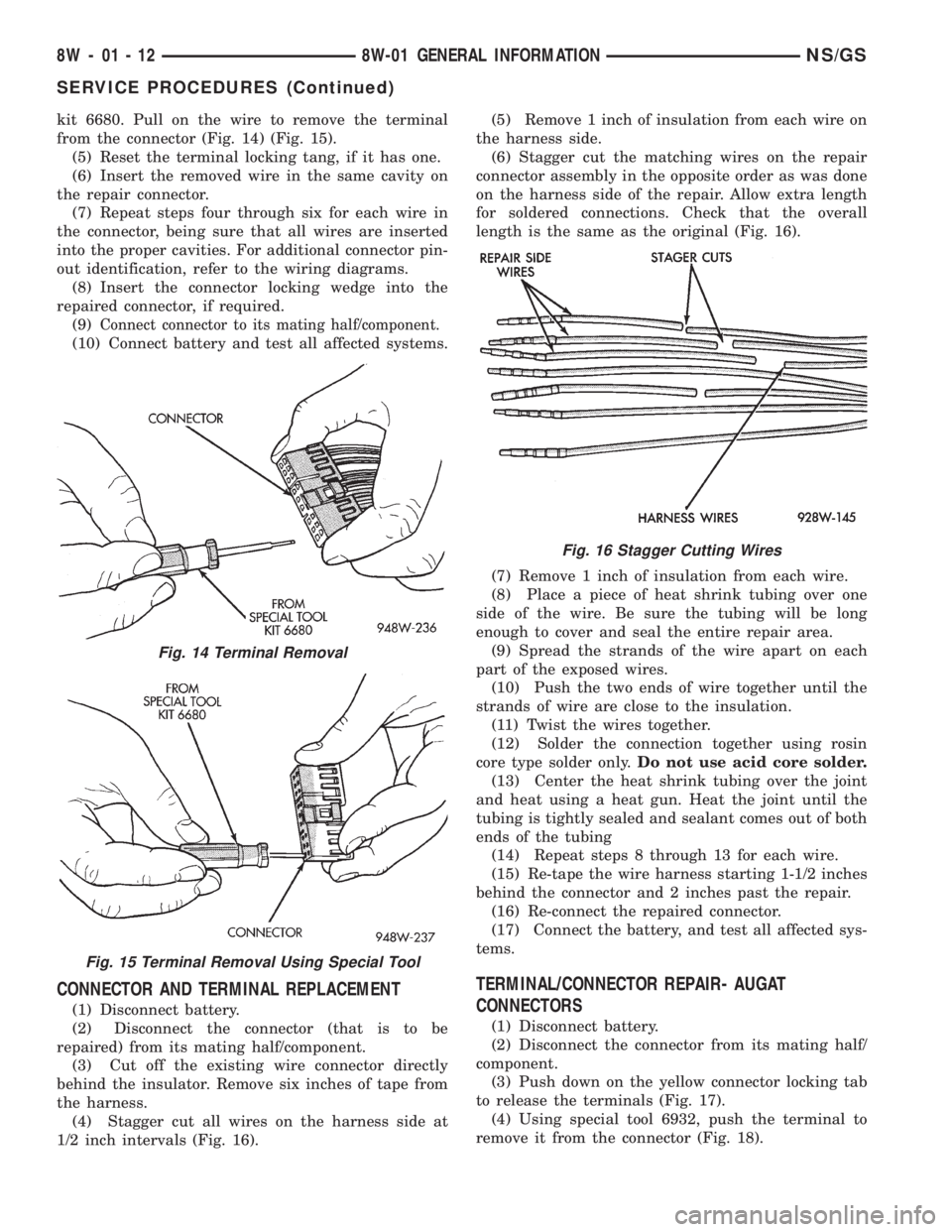
kit 6680. Pull on the wire to remove the terminal
from the connector (Fig. 14) (Fig. 15).
(5) Reset the terminal locking tang, if it has one.
(6) Insert the removed wire in the same cavity on
the repair connector.
(7) Repeat steps four through six for each wire in
the connector, being sure that all wires are inserted
into the proper cavities. For additional connector pin-
out identification, refer to the wiring diagrams.
(8) Insert the connector locking wedge into the
repaired connector, if required.
(9)
Connect connector to its mating half/component.
(10) Connect battery and test all affected systems.
CONNECTOR AND TERMINAL REPLACEMENT
(1) Disconnect battery.
(2) Disconnect the connector (that is to be
repaired) from its mating half/component.
(3) Cut off the existing wire connector directly
behind the insulator. Remove six inches of tape from
the harness.
(4) Stagger cut all wires on the harness side at
1/2 inch intervals (Fig. 16).(5) Remove 1 inch of insulation from each wire on
the harness side.
(6) Stagger cut the matching wires on the repair
connector assembly in the opposite order as was done
on the harness side of the repair. Allow extra length
for soldered connections. Check that the overall
length is the same as the original (Fig. 16).
(7) Remove 1 inch of insulation from each wire.
(8) Place a piece of heat shrink tubing over one
side of the wire. Be sure the tubing will be long
enough to cover and seal the entire repair area.
(9) Spread the strands of the wire apart on each
part of the exposed wires.
(10) Push the two ends of wire together until the
strands of wire are close to the insulation.
(11) Twist the wires together.
(12) Solder the connection together using rosin
core type solder only.Do not use acid core solder.
(13) Center the heat shrink tubing over the joint
and heat using a heat gun. Heat the joint until the
tubing is tightly sealed and sealant comes out of both
ends of the tubing
(14) Repeat steps 8 through 13 for each wire.
(15) Re-tape the wire harness starting 1-1/2 inches
behind the connector and 2 inches past the repair.
(16) Re-connect the repaired connector.
(17) Connect the battery, and test all affected sys-
tems.
TERMINAL/CONNECTOR REPAIR- AUGAT
CONNECTORS
(1) Disconnect battery.
(2) Disconnect the connector from its mating half/
component.
(3) Push down on the yellow connector locking tab
to release the terminals (Fig. 17).
(4) Using special tool 6932, push the terminal to
remove it from the connector (Fig. 18).
Fig. 14 Terminal Removal
Fig. 15 Terminal Removal Using Special Tool
Fig. 16 Stagger Cutting Wires
8W - 01 - 12 8W-01 GENERAL INFORMATIONNS/GS
SERVICE PROCEDURES (Continued)