battery replacement CHRYSLER VOYAGER 1996 User Guide
[x] Cancel search | Manufacturer: CHRYSLER, Model Year: 1996, Model line: VOYAGER, Model: CHRYSLER VOYAGER 1996Pages: 1938, PDF Size: 55.84 MB
Page 575 of 1938
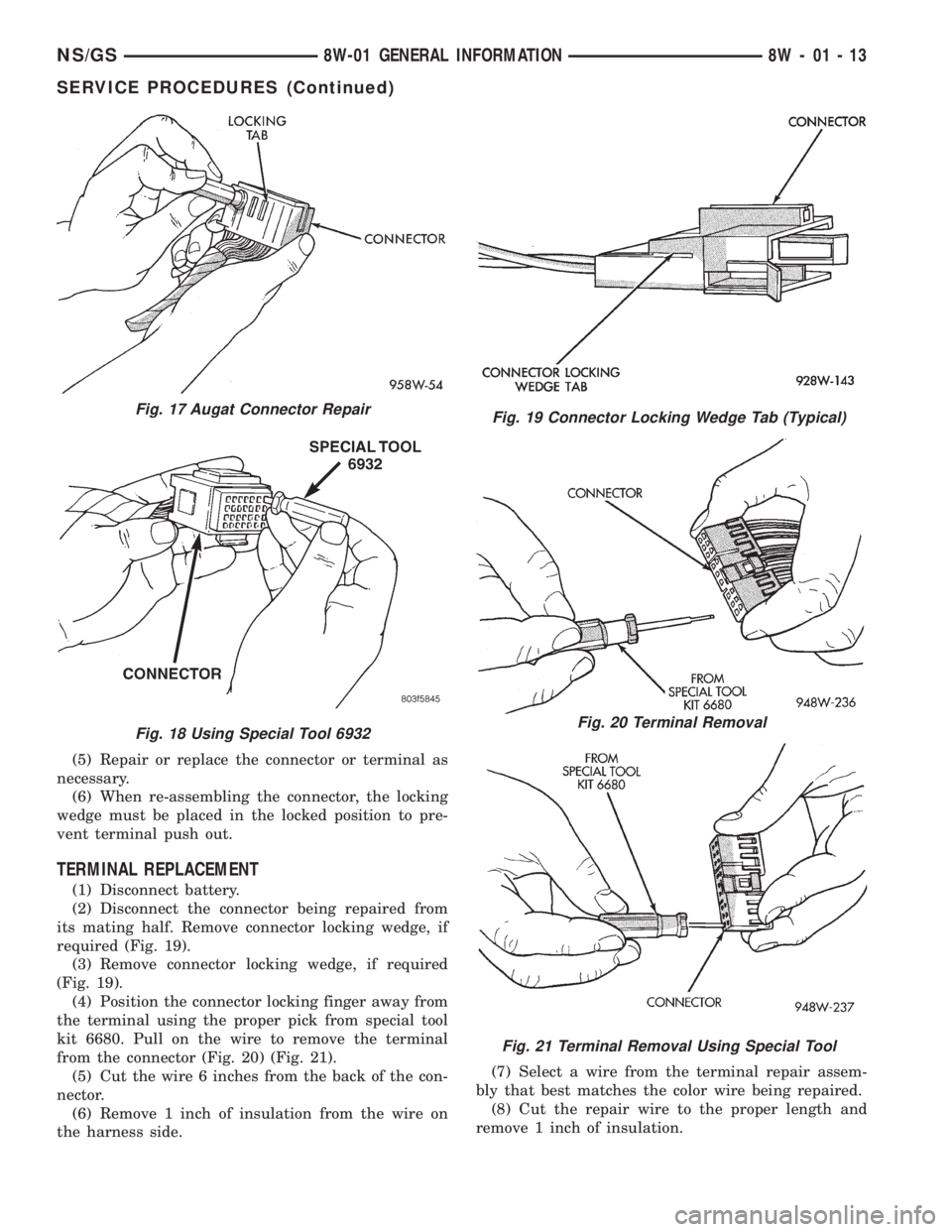
(5) Repair or replace the connector or terminal as
necessary.
(6) When re-assembling the connector, the locking
wedge must be placed in the locked position to pre-
vent terminal push out.
TERMINAL REPLACEMENT
(1) Disconnect battery.
(2) Disconnect the connector being repaired from
its mating half. Remove connector locking wedge, if
required (Fig. 19).
(3) Remove connector locking wedge, if required
(Fig. 19).
(4) Position the connector locking finger away from
the terminal using the proper pick from special tool
kit 6680. Pull on the wire to remove the terminal
from the connector (Fig. 20) (Fig. 21).
(5) Cut the wire 6 inches from the back of the con-
nector.
(6) Remove 1 inch of insulation from the wire on
the harness side.(7) Select a wire from the terminal repair assem-
bly that best matches the color wire being repaired.
(8) Cut the repair wire to the proper length and
remove 1 inch of insulation.
Fig. 17 Augat Connector Repair
Fig. 18 Using Special Tool 6932
Fig. 19 Connector Locking Wedge Tab (Typical)
Fig. 20 Terminal Removal
Fig. 21 Terminal Removal Using Special Tool
NS/GS8W-01 GENERAL INFORMATION 8W - 01 - 13
SERVICE PROCEDURES (Continued)
Page 576 of 1938
(9) Place a piece of heat shrink tubing over one
side of the wire. Make sure the tubing will be long
enough to cover and seal the entire repair area.
(10) Spread the strands of the wire apart on each
part of the exposed wires.
(11) Push the two ends of wire together until the
strands of wire are close to the insulation.
(12) Twist the wires together.
(13) Solder the connection together using rosin
core type solder only.Do not use acid core solder.
(14) Center the heat shrink tubing over the joint
and heat using a heat gun. Heat the joint until the
tubing is tightly sealed and sealant comes out of both
ends of the tubing.
(15) Insert the repaired wire into the connector.
(16) Install the connector locking wedge, if
required, and reconnect the connector to its mating
half/component.
(17) Re-tape the wire harness starting 1-1/2 inches
behind the connector and 2 inches past the repair.
(18) Connect battery, and test all affected systems.
DIODE REPLACEMENT
(1) Disconnect the battery.
(2) Locate the diode in the harness, and remove
the protective covering.
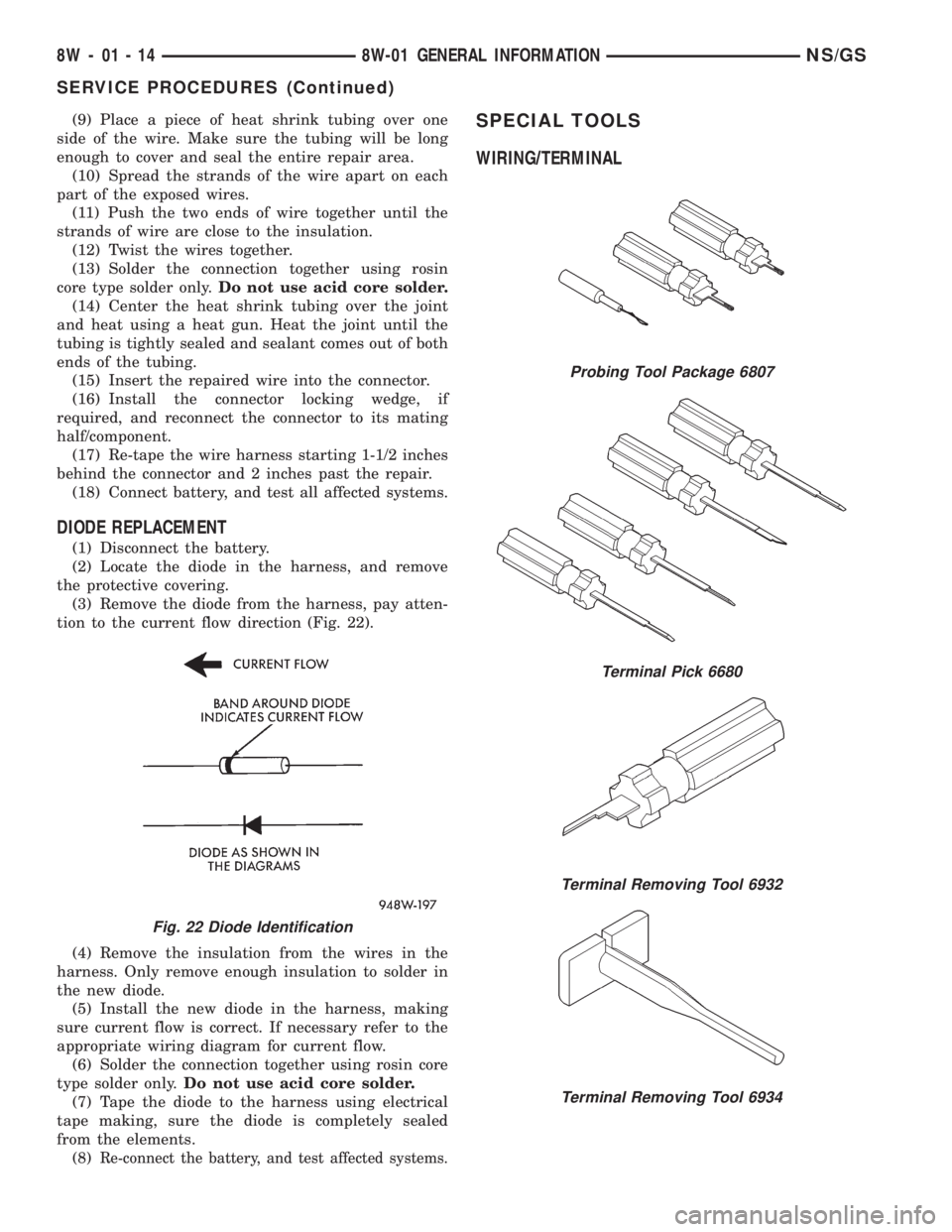
(3) Remove the diode from the harness, pay atten-
tion to the current flow direction (Fig. 22).
(4) Remove the insulation from the wires in the
harness. Only remove enough insulation to solder in
the new diode.
(5) Install the new diode in the harness, making
sure current flow is correct. If necessary refer to the
appropriate wiring diagram for current flow.
(6) Solder the connection together using rosin core
type solder only.Do not use acid core solder.
(7) Tape the diode to the harness using electrical
tape making, sure the diode is completely sealed
from the elements.
(8)
Re-connect the battery, and test affected systems.
SPECIAL TOOLS
WIRING/TERMINAL
Fig. 22 Diode Identification
Probing Tool Package 6807
Terminal Pick 6680
Terminal Removing Tool 6932
Terminal Removing Tool 6934
8W - 01 - 14 8W-01 GENERAL INFORMATIONNS/GS
SERVICE PROCEDURES (Continued)
Page 1059 of 1938
(2) Add an oil soluble dye (use as recommended by
manufacturer). Start the engine and let idle for
approximately 15 minutes. Check the oil dipstick to
make sure the dye is thoroughly mixed as indicated
with a bright yellow color under a black light.
(3) Using a black light, inspect the entire engine
for fluorescent dye, particularly at the suspected area
of oil leak. If the oil leak is found and identified,
repair per service manual instructions.
(4) If dye is not observed, drive the vehicle at var-
ious speeds for approximately 24km (15 miles), and
repeat inspection.
(5)If the oil leak source is not positively
identified at this time, proceed with the air leak
detection test method as follows:
(6) Disconnect the fresh air hose (makeup air) at
the cylinder head cover and plug or cap the nipple on
the cover.
(7) Remove the PCV valve hose from the cylinder
head cover. Cap or plug the PCV valve nipple on the
cover.
(8) Attach an air hose with pressure gauge and
regulator to the dipstick tube.
CAUTION: Do not subject the engine assembly to
more than 20.6 kpa (3 PSI) of test pressure.
(9) Gradually apply air pressure from 1 psi to 2.5
psi maximum while applying soapy water at the sus-
pected source. Adjust the regulator to the suitable
test pressure that provide the best bubbles which
will pinpoint the leak source. If the oil leak is
detected and identified, repair per service manual
procedures.
(10) If the leakage occurs at the rear oil seal area,
refer to the section, Inspection for Rear Seal Area
Leak.
(11) If no leaks are detected, turn off the air sup-
ply and remove the air hose and all plugs and caps.
Install the PCV valve and breather cap hose. Proceed
to next step.
(12) Clean the oil off the suspect oil leak area
using a suitable solvent. Drive the vehicle at various
speeds approximately 24 km (15 miles). Inspect the
engine for signs of an oil leak by using a black light.INSPECTION FOR REAR SEAL AREA LEAKS
Since it is sometimes difficult to determine the
source of an oil leak in the rear seal area of the
engine, a more involved inspection is necessary. The
following steps should be followed to help pinpoint
the source of the leak.
If the leakage occurs at the crankshaft rear oil seal
area:
(1) Disconnect the battery.
(2) Raise the vehicle.
(3) Remove torque converter or clutch housing
cover and inspect rear of block for evidence of oil.
Use a black light to check for the oil leak. If a leak is
present in this area remove transmission for further
inspection.
(a) Circular spray pattern generally indicates
seal leakage or crankshaft damage.
(b) Where leakage tends to run straight down,
possible causes are a porous block, oil galley cup
plug, bedplate to cylinder block mating surfaces
and seal bore. See proper repair procedures for
these items.
(4) If no leaks are detected, pressurized the crank-
case as outlined in the, Inspection (Engine oil Leaks
in general)
CAUTION: Do not exceed 20.6 kPa (3 psi).
(5) If the leak is not detected, very slowly turn the
crankshaft and watch for leakage. If a leak is
detected between the crankshaft and seal while
slowly turning the crankshaft, it is possible the
crankshaft seal surface is damaged. The seal area on
the crankshaft could have minor nicks or scratches
that can be polished out with emery cloth.
CAUTION: Use extreme caution when crankshaft
polishing is necessary to remove minor nicks and
scratches. The crankshaft seal flange is especially
machined to complement the function of the rear oil
seal.
(6) For bubbles that remain steady with shaft
rotation, no further inspection can be done until dis-
assembled.
(7) After the oil leak root cause and appropriate
corrective action have been identified. Refer to Rear
Crankshaft Seals, for proper replacement procedures.
NSENGINE 9 - 9
DIAGNOSIS AND TESTING (Continued)
Page 1119 of 1938
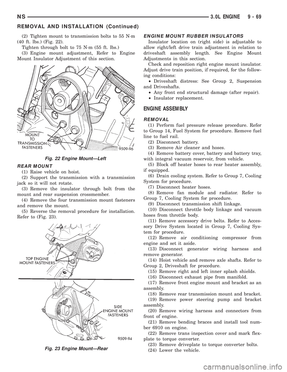
(2) Tighten mount to transmission bolts to 55 N´m
(40 ft. lbs.) (Fig. 22).
Tighten through bolt to 75 N´m (55 ft. lbs.)
(3) Engine mount adjustment, Refer to Engine
Mount Insulator Adjustment of this section.
REAR MOUNT
(1) Raise vehicle on hoist.
(2) Support the transmission with a transmission
jack so it will not rotate.
(3) Remove the insulator through bolt from the
mount and rear suspension crossmember.
(4) Remove the four transmission mount fasteners
and remove the mount.
(5) Reverse the removal procedure for installation.
Refer to (Fig. 23).
ENGINE MOUNT RUBBER INSULATORS
Insulator location on (right side) is adjustable to
allow right/left drive train adjustment in relation to
driveshaft assembly length. See Engine Mount
Adjustments in this section.
Check and reposition right engine mount insulator.
Adjust drive train position, if required, for the follow-
ing conditions:
²Driveshaft distress: See Group 2, Suspension
and Driveshafts.
²Any front end structural damage (after repair).
²Insulator replacement.
ENGINE ASSEMBLY
REMOVAL
(1) Perform fuel pressure release procedure. Refer
to Group 14, Fuel System for procedure. Remove fuel
line to fuel rail.
(2) Disconnect battery.
(3) Remove Air cleaner and hoses.
(4) Remove battery cover, battery and battery tray,
with integral vacuum reservoir, from vehicle.
(5) Block off heater hoses to rear heater assembly,
if equipped.
(6) Drain cooling system. Refer to Group 7, Cooling
System for procedure.
(7) Disconnect heater hoses.
(8) Remove fan module and radiator. Refer to
Group 7, Cooling System for procedure.
(9) Disconnect transmission shift linkage.
(10) Disconnect throttle body linkage and vacuum
hoses from throttle body.
(11) Remove accessory drive belts. Refer to Acces-
sory Drive System located in Group 7, Cooling Sys-
tem for procedure.
(12) Remove air conditioning compressor from
engine and set it aside.
(13) Disconnect generator wiring harness and
remove generator.
(14) Hoist vehicle and remove axle shafts. Refer to
Group 2, Driveshaft for procedure.
(15) Remove right and left inner splash shields.
(16) Disconnect exhaust pipe from manifold.
(17) Remove front engine mount and bracket as an
assembly.
(18) Remove rear transmission mount and bracket.
(19) Remove power steering pump and bracket
assembly.
(20) Remove wiring harness and connectors from
front of engine.
(21) Remove bending braces and install tool num-
ber 6910 on engine.
(22) Remove trans inspection cover and mark flex-
plate to torque converter.
(23) Remove driveplate to torque converter bolts.
(24) Lower the vehicle.
Fig. 22 Engine MountÐLeft
Fig. 23 Engine MountÐRear
NS3.0L ENGINE 9 - 69
REMOVAL AND INSTALLATION (Continued)
Page 1154 of 1938
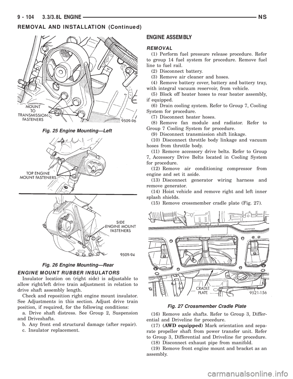
ENGINE MOUNT RUBBER INSULATORS
Insulator location on (right side) is adjustable to
allow right/left drive train adjustment in relation to
drive shaft assembly length.
Check and reposition right engine mount insulator.
See Adjustments in this section. Adjust drive train
position, if required, for the following conditions:
a. Drive shaft distress. See Group 2, Suspension
and Driveshafts.
b. Any front end structural damage (after repair).
c. Insulator replacement.
ENGINE ASSEMBLY
REMOVAL
(1) Perform fuel pressure release procedure. Refer
to group 14 fuel system for procedure. Remove fuel
line to fuel rail.
(2) Disconnect battery.
(3) Remove air cleaner and hoses.
(4) Remove battery cover, battery and battery tray,
with integral vacuum reservoir, from vehicle.
(5) Block off heater hoses to rear heater assembly,
if equipped.
(6) Drain cooling system. Refer to Group 7, Cooling
System for procedure.
(7) Disconnect heater hoses.
(8) Remove fan module and radiator. Refer to
Group 7 Cooling System for procedure.
(9) Disconnect transmission shift linkage.
(10) Disconnect throttle body linkage and vacuum
hoses from throttle body.
(11) Remove accessory drive belts. Refer to Group
7, Accessory Drive Belts located in Cooling System
for procedure.
(12) Remove air conditioning compressor from
engine and set it aside.
(13) Disconnect generator wiring harness and
remove generator.
(14) Hoist vehicle and remove right and left inner
splash shields.
(15) Remove crossmember cradle plate (Fig. 27).
(16) Remove axle shafts. Refer to Group 3, Differ-
ential and Driveline for procedure.
(17)(AWD equipped)Mark orientation and sepa-
rate propeller shaft from power transfer unit. Refer
to Group 3, Differential and Driveline for procedure.
(18) Disconnect exhaust pipe from manifold.
(19) Remove front engine mount and bracket as an
assembly.
Fig. 25 Engine MountingÐLeft
Fig. 26 Engine MountingÐRear
Fig. 27 Crossmember Cradle Plate
9 - 104 3.3/3.8L ENGINENS
REMOVAL AND INSTALLATION (Continued)
Page 1156 of 1938
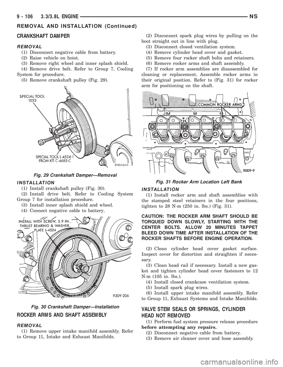
CRANKSHAFT DAMPER
REMOVAL
(1) Disconnect negative cable from battery.
(2) Raise vehicle on hoist.
(3) Remove right wheel and inner splash shield.
(4) Remove drive belt. Refer to Group 7, Cooling
System for procedure.
(5) Remove crankshaft pulley (Fig. 29).
INSTALLATION
(1) Install crankshaft pulley (Fig. 30).
(2) Install drive belt. Refer to Cooling System
Group 7 for installation procedure.
(3) Install inner splash shield and wheel.
(4) Connect negative cable to battery.
ROCKER ARMS AND SHAFT ASSEMBLY
REMOVAL
(1) Remove upper intake manifold assembly. Refer
to Group 11, Intake and Exhaust Manifolds.(2) Disconnect spark plug wires by pulling on the
boot straight out in line with plug.
(3) Disconnect closed ventilation system.
(4) Remove cylinder head cover and gasket.
(5) Remove four rocker shaft bolts and retainers.
(6) Remove rocker arms and shaft assembly.
(7) If rocker arm assemblies are disassembled for
cleaning or replacement. Assemble rocker arms in
their original position. Refer to (Fig. 31) for rocker
arm for positioning on the shaft.
INSTALLATION
(1) Install rocker arm and shaft assemblies with
the stamped steel retainers in the four positions,
tighten to 28 N´m (250 in. lbs.) (Fig. 31).
CAUTION: THE ROCKER ARM SHAFT SHOULD BE
TORQUED DOWN SLOWLY, STARTING WITH THE
CENTER BOLTS. ALLOW 20 MINUTES TAPPET
BLEED DOWN TIME AFTER INSTALLATION OF THE
ROCKER SHAFTS BEFORE ENGINE OPERATION.
(2) Clean cylinder head cover gasket surface.
Inspect cover for distortion and straighten if neces-
sary.
(3) Clean head rail if necessary. Install a new gas-
ket and tighten cylinder head cover fasteners to 12
N´m (105 in. lbs.).
(4) Install closed crankcase ventilation system.
(5) Install spark plug wires.
(6) Install upper intake manifold assembly. Refer
to Group 11, Exhaust Systems and Intake Manifolds.
VALVE STEM SEALS OR SPRINGS, CYLINDER
HEAD NOT REMOVED
(1) Perform fuel system pressure release procedure
before attempting any repairs.
(2) Disconnect negative cable from battery.
(3) Remove air cleaner cover and hose assembly.
Fig. 29 Crankshaft DamperÐRemoval
Fig. 30 Crankshaft DamperÐInstallation
Fig. 31 Rocker Arm Location Left Bank
9 - 106 3.3/3.8L ENGINENS
REMOVAL AND INSTALLATION (Continued)
Page 1237 of 1938
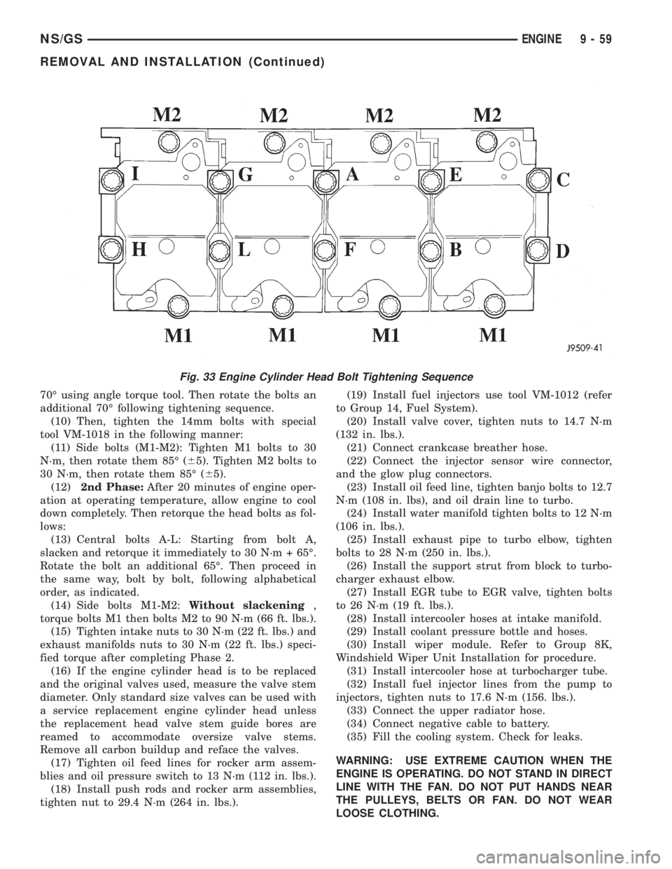
70É using angle torque tool. Then rotate the bolts an
additional 70É following tightening sequence.
(10) Then, tighten the 14mm bolts with special
tool VM-1018 in the following manner:
(11) Side bolts (M1-M2): Tighten M1 bolts to 30
N´m, then rotate them 85É (65). Tighten M2 bolts to
30 N´m, then rotate them 85É (65).
(12)2nd Phase:After 20 minutes of engine oper-
ation at operating temperature, allow engine to cool
down completely. Then retorque the head bolts as fol-
lows:
(13) Central bolts A-L: Starting from bolt A,
slacken and retorque it immediately to 30 N´m + 65É.
Rotate the bolt an additional 65É. Then proceed in
the same way, bolt by bolt, following alphabetical
order, as indicated.
(14) Side bolts M1-M2:Without slackening,
torque bolts M1 then bolts M2 to 90 N´m (66 ft. lbs.).
(15) Tighten intake nuts to 30 N´m (22 ft. lbs.) and
exhaust manifolds nuts to 30 N´m (22 ft. lbs.) speci-
fied torque after completing Phase 2.
(16) If the engine cylinder head is to be replaced
and the original valves used, measure the valve stem
diameter. Only standard size valves can be used with
a service replacement engine cylinder head unless
the replacement head valve stem guide bores are
reamed to accommodate oversize valve stems.
Remove all carbon buildup and reface the valves.
(17) Tighten oil feed lines for rocker arm assem-
blies and oil pressure switch to 13 N´m (112 in. lbs.).
(18) Install push rods and rocker arm assemblies,
tighten nut to 29.4 N´m (264 in. lbs.).(19) Install fuel injectors use tool VM-1012 (refer
to Group 14, Fuel System).
(20) Install valve cover, tighten nuts to 14.7 N´m
(132 in. lbs.).
(21) Connect crankcase breather hose.
(22) Connect the injector sensor wire connector,
and the glow plug connectors.
(23) Install oil feed line, tighten banjo bolts to 12.7
N´m (108 in. lbs), and oil drain line to turbo.
(24) Install water manifold tighten bolts to 12 N´m
(106 in. lbs.).
(25) Install exhaust pipe to turbo elbow, tighten
bolts to 28 N´m (250 in. lbs.).
(26) Install the support strut from block to turbo-
charger exhaust elbow.
(27) Install EGR tube to EGR valve, tighten bolts
to 26 N´m (19 ft. lbs.).
(28) Install intercooler hoses at intake manifold.
(29) Install coolant pressure bottle and hoses.
(30) Install wiper module. Refer to Group 8K,
Windshield Wiper Unit Installation for procedure.
(31) Install intercooler hose at turbocharger tube.
(32) Install fuel injector lines from the pump to
injectors, tighten nuts to 17.6 N´m (156. lbs.).
(33) Connect the upper radiator hose.
(34) Connect negative cable to battery.
(35) Fill the cooling system. Check for leaks.
WARNING: USE EXTREME CAUTION WHEN THE
ENGINE IS OPERATING. DO NOT STAND IN DIRECT
LINE WITH THE FAN. DO NOT PUT HANDS NEAR
THE PULLEYS, BELTS OR FAN. DO NOT WEAR
LOOSE CLOTHING.
Fig. 33 Engine Cylinder Head Bolt Tightening Sequence
NS/GSENGINE 9 - 59
REMOVAL AND INSTALLATION (Continued)
Page 1266 of 1938
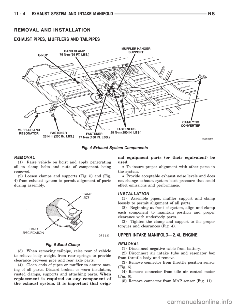
REMOVAL AND INSTALLATION
EXHAUST PIPES, MUFFLERS AND TAILPIPES
REMOVAL
(1) Raise vehicle on hoist and apply penetrating
oil to clamp bolts and nuts of component being
removed.
(2) Loosen clamps and supports (Fig. 5) and (Fig.
4) from exhaust system to permit alignment of parts
during assembly.
(3) When removing tailpipe, raise rear of vehicle
to relieve body weight from rear springs to provide
clearance between pipe and rear axle parts.
(4) Clean ends of pipes or muffler to assure mat-
ing of all parts. Discard broken or worn insulators,
rusted clamps, supports and attaching parts.When
replacement is required on any component of
the exhaust system. It is important that origi-nal equipment parts (or their equivalent) be
used;
²To insure proper alignment with other parts in
the system.
²Provide acceptable exhaust noise levels and does
not change exhaust system back pressure that could
effect emissions and performance.
INSTALLATION
(1) Assemble pipes, muffler support and clamp
loosely to permit alignment of all parts.
(2) Beginning at front of system, align and clamp
each component to maintain position and proper
clearance with underbody parts.
(3) Tighten the clamp and support to the proper
torques and clearances (Fig. 4).
UPPER INTAKE MANIFOLDÐ2.4L ENGINE
REMOVAL
(1) Disconnect negative cable from battery.
(2) Disconnect air intake tube and resonator box
from throttle body and remove.
(3) Remove connector from throttle position sensor
(Fig. 6).
(4) Remove connector from idle air control motor
(Fig. 6).
(5) Remove connector from MAP sensor (Fig. 11).
Fig. 4 Exhaust System Components
Fig. 5 Band Clamp
11 - 4 EXHAUST SYSTEM AND INTAKE MANIFOLDNS
Page 1283 of 1938
FRAME
INDEX
page page
REMOVAL AND INSTALLATION
FRONT CROSSMEMBER MOUNT BUSHINGS . . . 5
FRONT CROSSMEMBER................... 3SPECIFICATIONS
FRAME AND BODY OPENING DIMENSIONS.... 5
REMOVAL AND INSTALLATION
FRONT CROSSMEMBER
The front suspension crossmember must be
installed in the design location to achieve proper
front end suspension alignment. If the crossmember
is removed without applying reference marks on the
frame rails, align the crossmember according to the
dimensions provided in this group.
NOTE: If the caged nuts in the frame rails become
damaged and cannot be reused, a replacement nut
can be obtained through a MoparTParts supplier.
REMOVAL
(1) Disconnect battery negative cable.
(2) Remove steering column lower cover from
instrument panel. Refer to Group 8E, Instrument
Panel and Systems.
(3) Remove knee blocker reinforcement. Refer to
Group 8E, Instrument Panel and Systems.
(4) Position steering so front wheels are straight
ahead.
CAUTION: Do not rotate steering wheel after disen-
gaging lower coupling from steering gear, damage
to airbag clock spring can result.
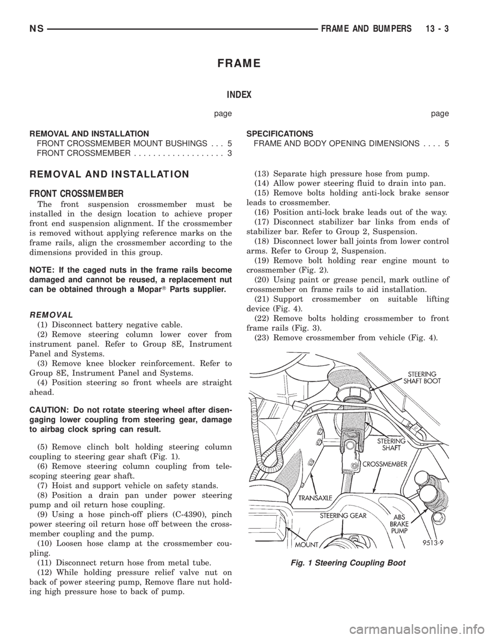
(5) Remove clinch bolt holding steering column
coupling to steering gear shaft (Fig. 1).
(6) Remove steering column coupling from tele-
scoping steering gear shaft.
(7) Hoist and support vehicle on safety stands.
(8) Position a drain pan under power steering
pump and oil return hose coupling.
(9) Using a hose pinch-off pliers (C-4390), pinch
power steering oil return hose off between the cross-
member coupling and the pump.
(10) Loosen hose clamp at the crossmember cou-
pling.
(11) Disconnect return hose from metal tube.
(12) While holding pressure relief valve nut on
back of power steering pump, Remove flare nut hold-
ing high pressure hose to back of pump.(13) Separate high pressure hose from pump.
(14) Allow power steering fluid to drain into pan.
(15) Remove bolts holding anti-lock brake sensor
leads to crossmember.
(16) Position anti-lock brake leads out of the way.
(17) Disconnect stabilizer bar links from ends of
stabilizer bar. Refer to Group 2, Suspension.
(18) Disconnect lower ball joints from lower control
arms. Refer to Group 2, Suspension.
(19) Remove bolt holding rear engine mount to
crossmember (Fig. 2).
(20) Using paint or grease pencil, mark outline of
crossmember on frame rails to aid installation.
(21) Support crossmember on suitable lifting
device (Fig. 4).
(22) Remove bolts holding crossmember to front
frame rails (Fig. 3).
(23) Remove crossmember from vehicle (Fig. 4).
Fig. 1 Steering Coupling Boot
NSFRAME AND BUMPERS 13 - 3
Page 1285 of 1938
(7) Connect lower ball joints to lower control arms.
Refer to Group 2, Suspension.
(8) Connect stabilizer bar links to ends of stabi-
lizer bar. Refer to Group 2, Suspension.
(9) Install bolts to hold anti-lock brake sensor
leads to crossmember.
(10) Install high pressure hose to pump.
(11) Connect return hose to metal tube.
(12) Tighten hose clamp at the crossmember cou-
pling.
(13) Remove pinch-off pliers.
(14) Position steering so front wheels are straight
ahead.
(15) Install steering column coupling to telescoping
steering gear shaft.
(16) Install clinch bolt to hold steering column cou-
pling to steering gear shaft.
(17) Install knee blocker reinforcement. Refer to
Group 8E, Instrument Panel and Systems.
(18) Install steering column lower cover from
instrument panel. Refer to Group 8E, Instrument
Panel and Systems.
(19) Connect battery negative cable.
FRONT CROSSMEMBER MOUNT BUSHINGS
REMOVAL
(1) Using paint or grease pencil, mark outline of
crossmember on frame rails.
(2) Loosen bolts holding crossmember to frame
rails.
(3) Remove bolt on bushing that requires replace-
ment.
(4) Allow crossmember to drop down enough to
gain clearance for bushing removal.
(5) Remove bushing from vehicle.
INSTALLATION
(1) Apply rubber lube or soap to replacement bush-
ing.(2) Insert lower half of bushing into square hole in
crossmember.
(3) Place upper half of bushing on top of cross-
member aligned to receive square tube protruding
upward from lower bushing half.
(4) Squeeze bushing halves together to ensure they
are properly mated.
(5) Lift crossmember upward to close gap between
the bushing and frame.
(6) Verify that lower bushing is fully seated into
crossmember and upper bushing.
(7) Install bolt to hold bushing and crossmember
to frame rail hand tight.
(8) Align crossmember to reference marks on
frame rails.
(9) Tighten crossmember to frame rails attaching
bolts to 163 N´m (120 ft. lbs.) torque.
SPECIFICATIONS
FRAME AND BODY OPENING DIMENSIONS
Frame dimensions are listed in metric scale. All
dimensions are from center to center of Principal
Locating Point (PLP), or from center to center of PLP
and fastener location.
VEHICLE PREPARATION
Position the vehicle on a frame alignment rack,
refer to instructions provided with equipment being
used. Adjust the vehicle PLP heights to the specified
dimension above the work surface (datum line). Ver-
tical dimensions can be taken from the datum line to
the locations indicated were applicable. Refer to (Fig.
5), (Fig. 6), (Fig. 7), (Fig. 8), (Fig. 9), (Fig. 10) and
(Fig. 11) for proper dimensions.
NSFRAME AND BUMPERS 13 - 5
REMOVAL AND INSTALLATION (Continued)