tire type CHRYSLER VOYAGER 1996 Service Manual
[x] Cancel search | Manufacturer: CHRYSLER, Model Year: 1996, Model line: VOYAGER, Model: CHRYSLER VOYAGER 1996Pages: 1938, PDF Size: 55.84 MB
Page 36 of 1938
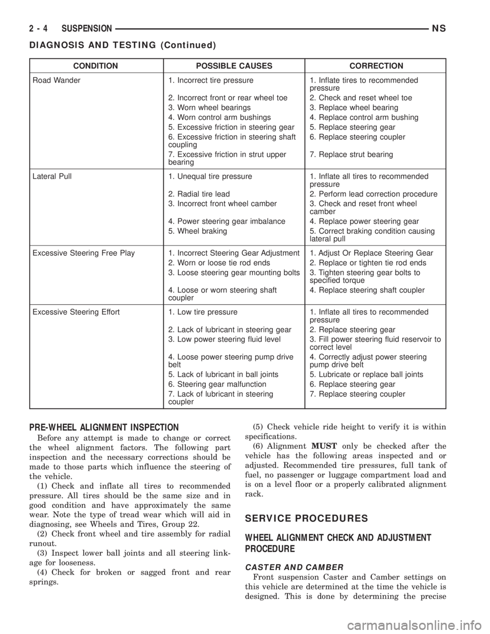
CONDITION POSSIBLE CAUSES CORRECTION
Road Wander 1. Incorrect tire pressure 1. Inflate tires to recommended
pressure
2. Incorrect front or rear wheel toe 2. Check and reset wheel toe
3. Worn wheel bearings 3. Replace wheel bearing
4. Worn control arm bushings 4. Replace control arm bushing
5. Excessive friction in steering gear 5. Replace steering gear
6. Excessive friction in steering shaft
coupling6. Replace steering coupler
7. Excessive friction in strut upper
bearing7. Replace strut bearing
Lateral Pull 1. Unequal tire pressure 1. Inflate all tires to recommended
pressure
2. Radial tire lead 2. Perform lead correction procedure
3. Incorrect front wheel camber 3. Check and reset front wheel
camber
4. Power steering gear imbalance 4. Replace power steering gear
5. Wheel braking 5. Correct braking condition causing
lateral pull
Excessive Steering Free Play 1. Incorrect Steering Gear Adjustment 1. Adjust Or Replace Steering Gear
2. Worn or loose tie rod ends 2. Replace or tighten tie rod ends
3. Loose steering gear mounting bolts 3. Tighten steering gear bolts to
specified torque
4. Loose or worn steering shaft
coupler4. Replace steering shaft coupler
Excessive Steering Effort 1. Low tire pressure 1. Inflate all tires to recommended
pressure
2. Lack of lubricant in steering gear 2. Replace steering gear
3. Low power steering fluid level 3. Fill power steering fluid reservoir to
correct level
4. Loose power steering pump drive
belt4. Correctly adjust power steering
pump drive belt
5. Lack of lubricant in ball joints 5. Lubricate or replace ball joints
6. Steering gear malfunction 6. Replace steering gear
7. Lack of lubricant in steering
coupler7. Replace steering coupler
PRE-WHEEL ALIGNMENT INSPECTION
Before any attempt is made to change or correct
the wheel alignment factors. The following part
inspection and the necessary corrections should be
made to those parts which influence the steering of
the vehicle.
(1) Check and inflate all tires to recommended
pressure. All tires should be the same size and in
good condition and have approximately the same
wear. Note the type of tread wear which will aid in
diagnosing, see Wheels and Tires, Group 22.
(2) Check front wheel and tire assembly for radial
runout.
(3) Inspect lower ball joints and all steering link-
age for looseness.
(4) Check for broken or sagged front and rear
springs.(5) Check vehicle ride height to verify it is within
specifications.
(6) AlignmentMUSTonly be checked after the
vehicle has the following areas inspected and or
adjusted. Recommended tire pressures, full tank of
fuel, no passenger or luggage compartment load and
is on a level floor or a properly calibrated alignment
rack.
SERVICE PROCEDURES
WHEEL ALIGNMENT CHECK AND ADJUSTMENT
PROCEDURE
CASTER AND CAMBER
Front suspension Caster and Camber settings on
this vehicle are determined at the time the vehicle is
designed. This is done by determining the precise
2 - 4 SUSPENSIONNS
DIAGNOSIS AND TESTING (Continued)
Page 45 of 1938
instructions included with the thread insert for the
detailed procedure used for the installation of the
thread insert.
NOTE: The thread inserts for this application are
for the repair of M8x1.25 and M10x1.5 threads. Be
sure the correct tools are used for the required
thread insert size.
TOOL REQUIREMENT FOR M8x1.25 Thread
²8.3mm (5/16 in.) Drill Bit
²120É Countersink
²Heli-CoiltTap #4863-8
²Heli-CoiltGage #4624-8
²Heli-CoiltHand Inserting Tool 7751-8
²Needle Nose Pliers ± For Removal Of Thread
Insert Driving Tang
TOOL REQUIREMENT FOR M10x1.5 Thread
²10.5mm (25/64 in.) Drill Bit
²120É Countersink
²Heli-CoiltTap #4863-10
²Heli-CoiltGage #4624-10
²Heli-CoiltHand Inserting Tool 7751-10
²Needle Nose Pliers ± For Removal Of Thread
Insert Driving Tang
REMOVAL AND INSTALLATION
Mc PHERSON STRUT
REMOVAL
WARNING: DO NOT REMOVE THE NUT FROM THE
STRUT ROD WHILE STRUT ASSEMBLY IS
INSTALLED IN VEHICLE, OR BEFORE STRUT
ASSEMBLY SPRING IS COMPRESSED.
(1) Raise vehicle on jack stands or centered on a
frame contact type hoist. See Hoisting in the Lubri-
cation and Maintenance section of this service man-
ual, for the required lifting procedure to be used for
this vehicle.
(2) Remove the wheel and tire assembly from loca-
tion on front of vehicle requiring strut removal.
(3) If both strut assemblies are to be removed,
mark the strut assemblies right or left according to
which side of the vehicle they were removed from.
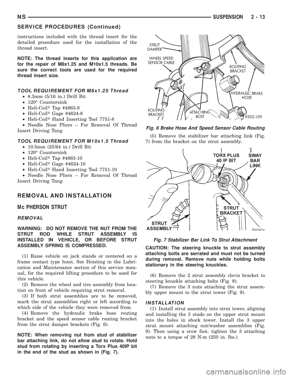
(4) Remove the hydraulic brake hose routing
bracket and the speed sensor cable routing bracket
from the strut damper brackets (Fig. 6).
NOTE: When removing nut from stud of stabilizer
bar attaching link, do not allow stud to rotate. Hold
stud from rotating by inserting a Torx Plus 40IP bit
in the end of the stud as shown in (Fig. 7).(5) Remove the stabilizer bar attaching link (Fig.
7) from the bracket on the strut assembly.
CAUTION: The steering knuckle to strut assembly
attaching bolts are serrated and must not be turned
during removal. Remove nuts while holding bolts
stationary in the steering knuckles.
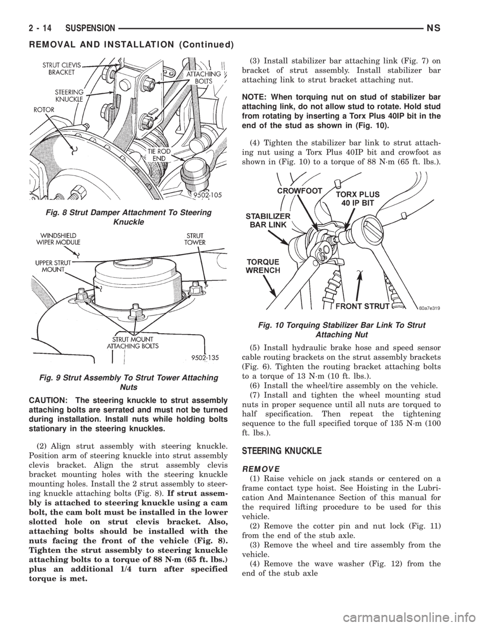
(6) Remove the 2 strut assembly clevis bracket to
steering knuckle attaching bolts (Fig. 8).
(7) Remove the 3 nuts attaching the strut assem-
bly upper mount to the strut tower (Fig. 9).
INSTALLATION
(1) Install strut assembly into strut tower, aligning
and installing the 3 studs on the upper strut mount
into the holes in shock tower. Install the 3 upper
strut mount attaching nut/washer assemblies (Fig.
9). Then using a crow foot. tighten the 3 attaching
nuts to a torque of 28 N´m (250 in. lbs.).
Fig. 6 Brake Hose And Speed Sensor Cable Routing
Fig. 7 Stabilizer Bar Link To Strut Attachment
NSSUSPENSION 2 - 13
SERVICE PROCEDURES (Continued)
Page 46 of 1938
CAUTION: The steering knuckle to strut assembly
attaching bolts are serrated and must not be turned
during installation. Install nuts while holding bolts
stationary in the steering knuckles.
(2) Align strut assembly with steering knuckle.
Position arm of steering knuckle into strut assembly
clevis bracket. Align the strut assembly clevis
bracket mounting holes with the steering knuckle
mounting holes. Install the 2 strut assembly to steer-
ing knuckle attaching bolts (Fig. 8).If strut assem-
bly is attached to steering knuckle using a cam
bolt, the cam bolt must be installed in the lower
slotted hole on strut clevis bracket. Also,
attaching bolts should be installed with the
nuts facing the front of the vehicle (Fig. 8).
Tighten the strut assembly to steering knuckle
attaching bolts to a torque of 88 N´m (65 ft. lbs.)
plus an additional 1/4 turn after specified
torque is met.(3) Install stabilizer bar attaching link (Fig. 7) on
bracket of strut assembly. Install stabilizer bar
attaching link to strut bracket attaching nut.
NOTE: When torquing nut on stud of stabilizer bar
attaching link, do not allow stud to rotate. Hold stud
from rotating by inserting a Torx Plus 40IP bit in the
end of the stud as shown in (Fig. 10).
(4) Tighten the stabilizer bar link to strut attach-
ing nut using a Torx Plus 40IP bit and crowfoot as
shown in (Fig. 10) to a torque of 88 N´m (65 ft. lbs.).
(5) Install hydraulic brake hose and speed sensor
cable routing brackets on the strut assembly brackets
(Fig. 6). Tighten the routing bracket attaching bolts
to a torque of 13 N´m (10 ft. lbs.).
(6) Install the wheel/tire assembly on the vehicle.
(7) Install and tighten the wheel mounting stud
nuts in proper sequence until all nuts are torqued to
half specification. Then repeat the tightening
sequence to the full specified torque of 135 N´m (100
ft. lbs.).
STEERING KNUCKLE
REMOVE
(1) Raise vehicle on jack stands or centered on a
frame contact type hoist. See Hoisting in the Lubri-
cation And Maintenance Section of this manual for
the required lifting procedure to be used for this
vehicle.
(2) Remove the cotter pin and nut lock (Fig. 11)
from the end of the stub axle.
(3) Remove the wheel and tire assembly from the
vehicle.
(4) Remove the wave washer (Fig. 12) from the
end of the stub axle
Fig. 8 Strut Damper Attachment To Steering
Knuckle
Fig. 9 Strut Assembly To Strut Tower Attaching
Nuts
Fig. 10 Torquing Stabilizer Bar Link To Strut
Attaching Nut
2 - 14 SUSPENSIONNS
REMOVAL AND INSTALLATION (Continued)
Page 51 of 1938
LOWER CONTROL ARM
REMOVE
(1) Raise vehicle on jack stands or centered on a
frame contact type hoist. See Hoisting in the Lubri-
cation and Maintenance section of this manual, for
the required lifting procedure to be used for this
vehicle.
(2) Remove wheel and tire assembly from the side
of vehicle requiring service to the lower control arm.
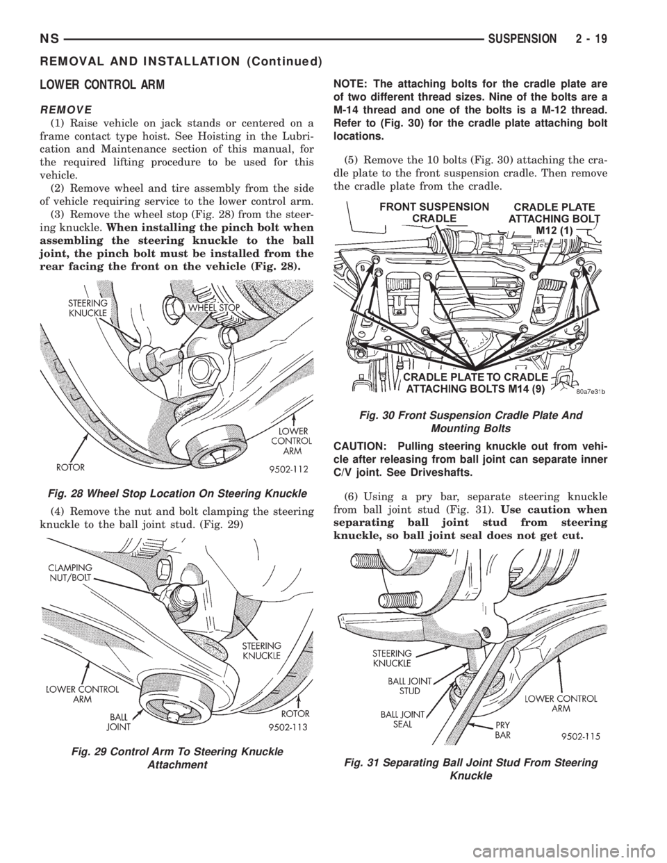
(3) Remove the wheel stop (Fig. 28) from the steer-
ing knuckle.When installing the pinch bolt when
assembling the steering knuckle to the ball
joint, the pinch bolt must be installed from the
rear facing the front on the vehicle (Fig. 28).
(4) Remove the nut and bolt clamping the steering
knuckle to the ball joint stud. (Fig. 29)NOTE: The attaching bolts for the cradle plate are
of two different thread sizes. Nine of the bolts are a
M-14 thread and one of the bolts is a M-12 thread.
Refer to (Fig. 30) for the cradle plate attaching bolt
locations.
(5) Remove the 10 bolts (Fig. 30) attaching the cra-
dle plate to the front suspension cradle. Then remove
the cradle plate from the cradle.
CAUTION: Pulling steering knuckle out from vehi-
cle after releasing from ball joint can separate inner
C/V joint. See Driveshafts.
(6) Using a pry bar, separate steering knuckle
from ball joint stud (Fig. 31).Use caution when
separating ball joint stud from steering
knuckle, so ball joint seal does not get cut.
Fig. 28 Wheel Stop Location On Steering Knuckle
Fig. 29 Control Arm To Steering Knuckle
Attachment
Fig. 30 Front Suspension Cradle Plate And
Mounting Bolts
Fig. 31 Separating Ball Joint Stud From Steering
Knuckle
NSSUSPENSION 2 - 19
REMOVAL AND INSTALLATION (Continued)
Page 58 of 1938
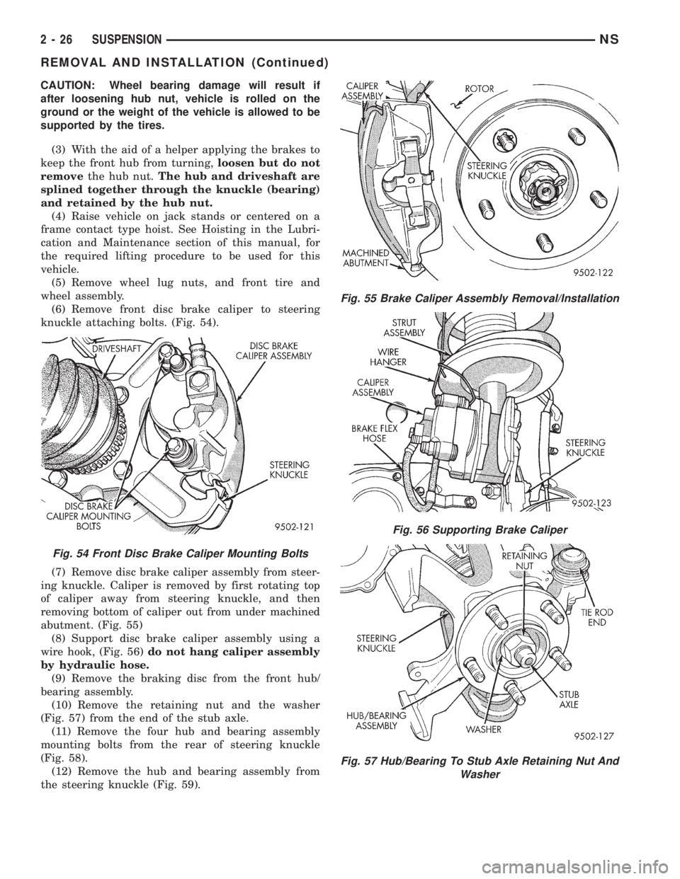
CAUTION: Wheel bearing damage will result if
after loosening hub nut, vehicle is rolled on the
ground or the weight of the vehicle is allowed to be
supported by the tires.
(3) With the aid of a helper applying the brakes to
keep the front hub from turning,loosen but do not
removethe hub nut.The hub and driveshaft are
splined together through the knuckle (bearing)
and retained by the hub nut.
(4) Raise vehicle on jack stands or centered on a
frame contact type hoist. See Hoisting in the Lubri-
cation and Maintenance section of this manual, for
the required lifting procedure to be used for this
vehicle.
(5) Remove wheel lug nuts, and front tire and
wheel assembly.
(6) Remove front disc brake caliper to steering
knuckle attaching bolts. (Fig. 54).
(7) Remove disc brake caliper assembly from steer-
ing knuckle. Caliper is removed by first rotating top
of caliper away from steering knuckle, and then
removing bottom of caliper out from under machined
abutment. (Fig. 55)
(8) Support disc brake caliper assembly using a
wire hook, (Fig. 56)do not hang caliper assembly
by hydraulic hose.
(9) Remove the braking disc from the front hub/
bearing assembly.
(10) Remove the retaining nut and the washer
(Fig. 57) from the end of the stub axle.
(11) Remove the four hub and bearing assembly
mounting bolts from the rear of steering knuckle
(Fig. 58).
(12) Remove the hub and bearing assembly from
the steering knuckle (Fig. 59).
Fig. 54 Front Disc Brake Caliper Mounting Bolts
Fig. 55 Brake Caliper Assembly Removal/Installation
Fig. 56 Supporting Brake Caliper
Fig. 57 Hub/Bearing To Stub Axle Retaining Nut And
Washer
2 - 26 SUSPENSIONNS
REMOVAL AND INSTALLATION (Continued)
Page 60 of 1938
sequence until all nuts are torqued to half specifica-
tion. Then repeat the tightening sequence to the full
specified torque of 129 N´m (95 ft. lbs.).
(7) Lower vehicle to the ground.
CAUTION: When tightening hub/bearing assembly
to stub shaft retaining nut, do not exceed the max-
imum torque of 244 N´m (180 ft. lbs.).
(8) With vehicle brakes applied to keep vehicle
from moving, torque stub shaft to hub/bearing assem-
bly retaining nut to 244 N´m (180 ft. lbs.).
(9) Check the Toe setting on the vehicle and reset
if not within specifications.
FRONT WHEEL MOUNTING STUDS
REMOVE
CAUTION: If a wheel attaching stud needs to be
replaced in the hub and bearing assembly the studs
CAN NOT be hammered out of the hub flange. If a
stud is removed by hammering it out of the bearing
flange, damage to the hub and bearing assembly
will occur leading to premature bearing failure.
The following procedure and special tools shown
MUST BEused when replacing wheel attaching
studs.
The hub and bearing assembly does not require
removal from the steering knuckle to replace wheel
attaching studs in the hub and bearing assembly.
(1) Raise vehicle on jackstands or centered on a
frame contact type hoist. See Hoisting in the Lubri-
cation and Maintenance section of this manual for
the required lifting procedure to be used for this
vehicle.
(2) Remove the front wheel and tire assembly from
the vehicle.
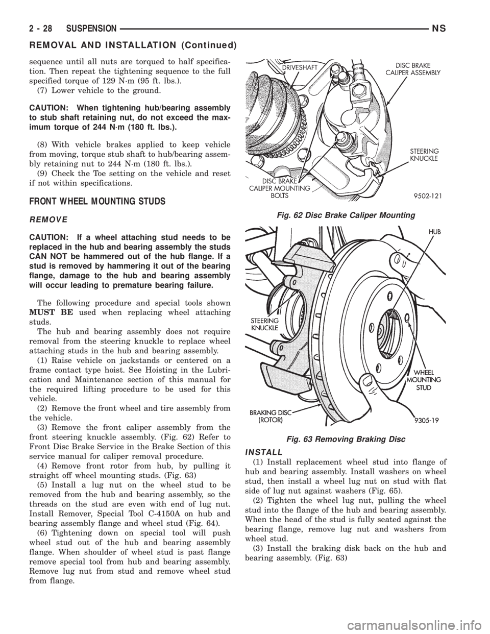
(3) Remove the front caliper assembly from the
front steering knuckle assembly. (Fig. 62) Refer to
Front Disc Brake Service in the Brake Section of this
service manual for caliper removal procedure.
(4) Remove front rotor from hub, by pulling it
straight off wheel mounting studs. (Fig. 63)
(5) Install a lug nut on the wheel stud to be
removed from the hub and bearing assembly, so the
threads on the stud are even with end of lug nut.
Install Remover, Special Tool C-4150A on hub and
bearing assembly flange and wheel stud (Fig. 64).
(6) Tightening down on special tool will push
wheel stud out of the hub and bearing assembly
flange. When shoulder of wheel stud is past flange
remove special tool from hub and bearing assembly.
Remove lug nut from stud and remove wheel stud
from flange.
INSTALL
(1) Install replacement wheel stud into flange of
hub and bearing assembly. Install washers on wheel
stud, then install a wheel lug nut on stud with flat
side of lug nut against washers (Fig. 65).
(2) Tighten the wheel lug nut, pulling the wheel
stud into the flange of the hub and bearing assembly.
When the head of the stud is fully seated against the
bearing flange, remove lug nut and washers from
wheel stud.
(3) Install the braking disk back on the hub and
bearing assembly. (Fig. 63)
Fig. 62 Disc Brake Caliper Mounting
Fig. 63 Removing Braking Disc
2 - 28 SUSPENSIONNS
REMOVAL AND INSTALLATION (Continued)
Page 61 of 1938
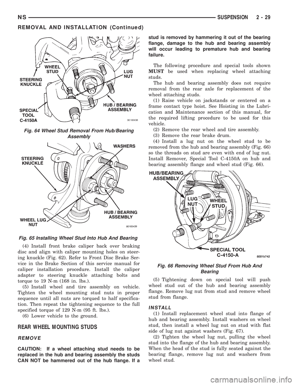
(4) Install front brake caliper back over braking
disc and align with caliper mounting holes on steer-
ing knuckle (Fig. 62). Refer to Front Disc Brake Ser-
vice in the Brake Section of this service manual for
caliper installation procedure. Install the caliper
adapter to steering knuckle attaching bolts and
torque to 19 N´m (168 in. lbs.).
(5) Install wheel and tire assembly on vehicle.
Tighten the wheel mounting stud nuts in proper
sequence until all nuts are torqued to half specifica-
tion. Then repeat the tightening sequence to the full
specified torque of 129 N´m (95 ft. lbs.).
(6) Lower vehicle to the ground.
REAR WHEEL MOUNTING STUDS
REMOVE
CAUTION: If a wheel attaching stud needs to be
replaced in the hub and bearing assembly the studs
CAN NOT be hammered out of the hub flange. If astud is removed by hammering it out of the bearing
flange, damage to the hub and bearing assembly
will occur leading to premature hub and bearing
failure.
The following procedure and special tools shown
MUSTbe used when replacing wheel attaching
studs.
The hub and bearing assembly does not require
removal from the rear axle for replacement of the
wheel attaching studs.
(1) Raise vehicle on jackstands or centered on a
frame contact type hoist. See Hoisting in the Lubri-
cation and Maintenance section of this manual, for
the required lifting procedure to be used for this
vehicle.
(2) Remove the rear wheel and tire assembly.
(3) Remove the rear brake drum.
(4) Install a lug nut on the wheel stud to be
removed from the hub and bearing assembly (Fig. 66)
so the threads on stud are even with end of lug nut.
Install Remover, Special Tool C-4150A on hub and
bearing assembly flange and wheel stud (Fig. 66).
(5) Tightening down on special tool will push
wheel stud out of the hub and bearing assembly
flange. Remove lug nut from stud and remove wheel
stud from flange.
INSTALL
(1) Install replacement wheel stud into flange of
hub and bearing assembly. Install washers on wheel
stud, then install a wheel lug nut on stud with flat
side of lug nut against washers (Fig. 67).
(2) Tighten the wheel lug nut, pulling the wheel
stud into the flange of the hub and bearing assembly.
When the head of the stud is fully seated against the
bearing flange, remove lug nut and washers from
wheel stud.
Fig. 64 Wheel Stud Removal From Hub/Bearing
Assembly
Fig. 65 Installing Wheel Stud Into Hub And Bearing
Fig. 66 Removing Wheel Stud From Hub And
Bearing
NSSUSPENSION 2 - 29
REMOVAL AND INSTALLATION (Continued)
Page 78 of 1938
INSTALLATION
(1) For installation, reverse removal procedure.
Tighten bolts to 61 N´m (45 ft. lbs.).
STABILIZER BAR
REMOVAL
(1) Raise vehicle. Vehicle is to be raised and sup-
ported on jack stands or on a frame contact type
hoist. See Hoisting in the Lubrication and Mainte-
nance section of this service manual.
(2) Remove the 2 lower bolts which hold the stabi-
lizer bar to the link arm on each side of the vehicle.
(3) Loosen but do not fully remove the four bolts
that attach the stabilizer bar bushing retainers to
the rear axle brackets.
(4) While holding the stabilizer bar in place. Fully
remove the 4 bolts loosened in step 3.
(5) Remove the stabilizer bar from the vehicle.
(6) If the link arms need to be serviced, remove
the upper link arm to bracket bolt. Then remove link
arm from frame rail attaching bracket.
INSPECTION
Inspect for broken or distorted clamps, retainers,
and bushings. If bushing replacement is required, the
stabilizer bar to axle bushings can be removed from
the stabilizer bar by opening the split.
INSTALLATION
(1) Install the link arms onto the frame rail brack-
ets. DO NOT TIGHTEN.
(2) Position the axle to stabilizer bar bushings on
the stabilizer bar with the slit in the bushings facing
up.(3) Lift the stabilizer bar onto the rear axle and
install the retainers and the four mounting bolts. DO
NOT TIGHTEN.
(4) Install the two lower link arm bolts on the sta-
bilizer bar. DO NOT TIGHTEN.
(5) Lower the vehicle so that the full weight of the
vehicle is on all four tires. With the vehicle at its
curb height, tighten all attaching bolts to the torques
listed below.
²Stabilizer bar bushing to axle bracket bolts 61
N´m (45 ft. lbs.)
²Link arm to frame rail bracket 61 N´m (45 ft.
lbs.)
²Stabilizer bar to link arm 61 N´m (45 ft. lbs.)
²Frame rail bracket to frame rail 61 N´m (45 ft.
lbs.)
JOUNCE BUMPER
There are two types of jounce bumpers available
depending on which suspension option the vehicle is
equipped with.
REMOVAL-STANDARD
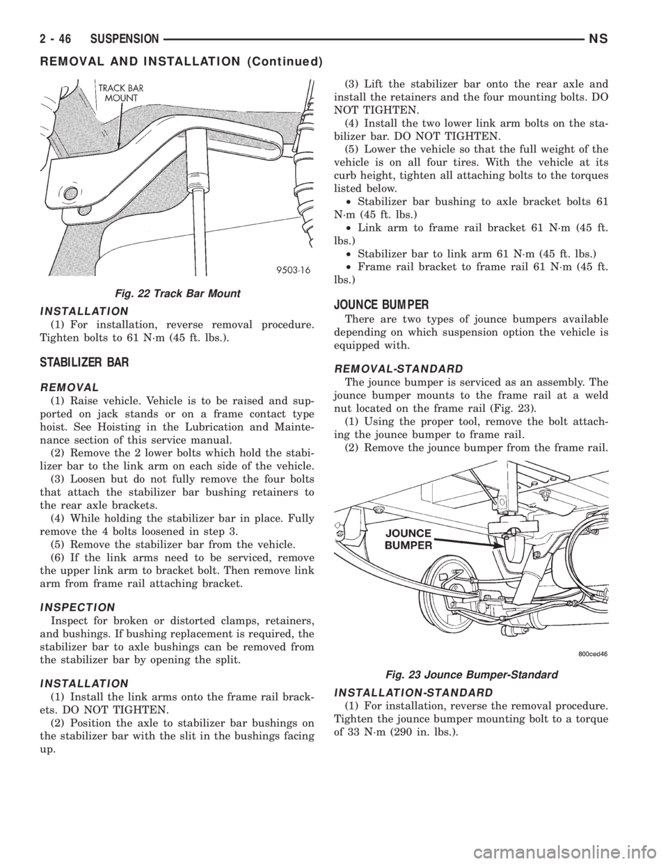
The jounce bumper is serviced as an assembly. The
jounce bumper mounts to the frame rail at a weld
nut located on the frame rail (Fig. 23).
(1) Using the proper tool, remove the bolt attach-
ing the jounce bumper to frame rail.
(2) Remove the jounce bumper from the frame rail.
INSTALLATION-STANDARD
(1) For installation, reverse the removal procedure.
Tighten the jounce bumper mounting bolt to a torque
of 33 N´m (290 in. lbs.).
Fig. 22 Track Bar Mount
Fig. 23 Jounce Bumper-Standard
2 - 46 SUSPENSIONNS
REMOVAL AND INSTALLATION (Continued)
Page 99 of 1938
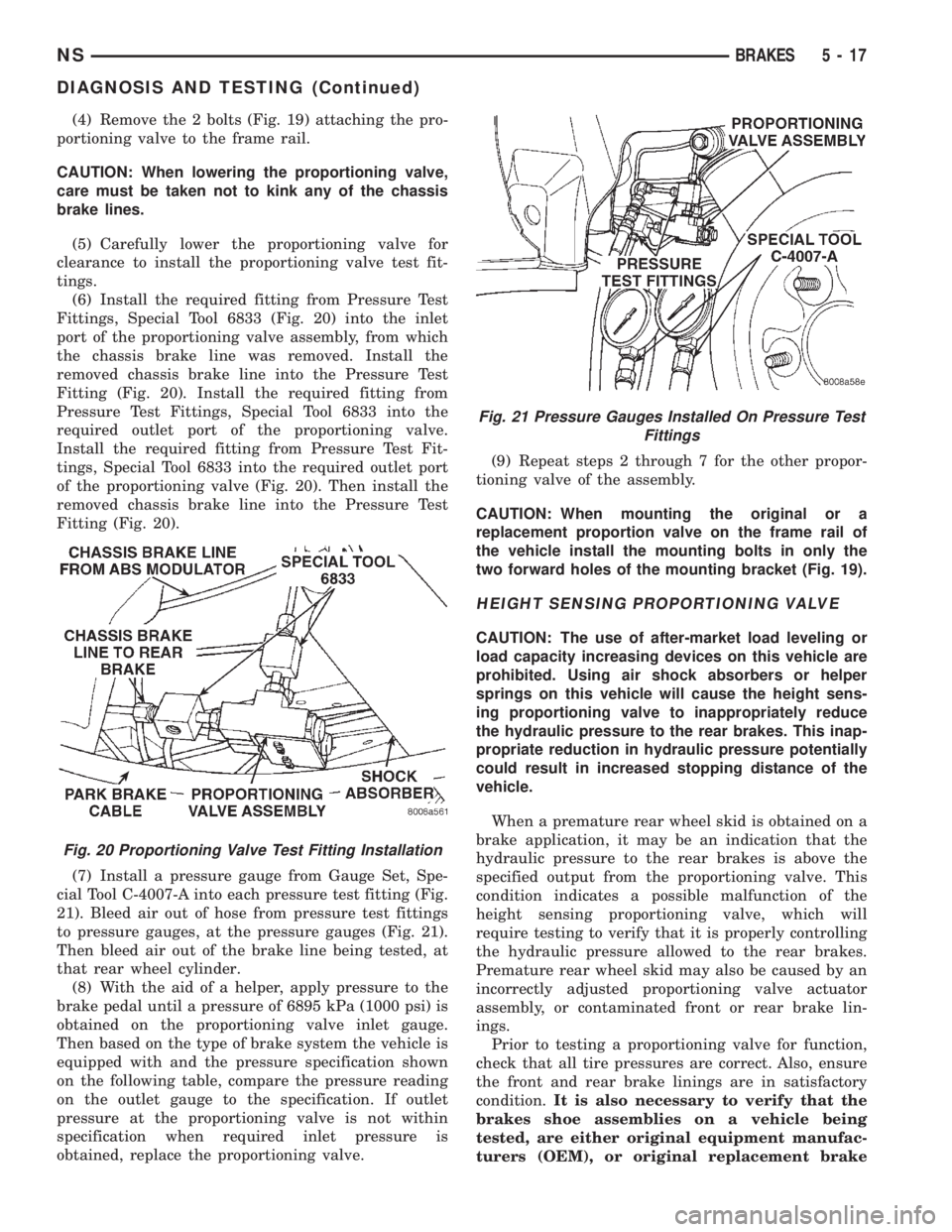
(4) Remove the 2 bolts (Fig. 19) attaching the pro-
portioning valve to the frame rail.
CAUTION: When lowering the proportioning valve,
care must be taken not to kink any of the chassis
brake lines.
(5) Carefully lower the proportioning valve for
clearance to install the proportioning valve test fit-
tings.
(6) Install the required fitting from Pressure Test
Fittings, Special Tool 6833 (Fig. 20) into the inlet
port of the proportioning valve assembly, from which
the chassis brake line was removed. Install the
removed chassis brake line into the Pressure Test
Fitting (Fig. 20). Install the required fitting from
Pressure Test Fittings, Special Tool 6833 into the
required outlet port of the proportioning valve.
Install the required fitting from Pressure Test Fit-
tings, Special Tool 6833 into the required outlet port
of the proportioning valve (Fig. 20). Then install the
removed chassis brake line into the Pressure Test
Fitting (Fig. 20).
(7) Install a pressure gauge from Gauge Set, Spe-
cial Tool C-4007-A into each pressure test fitting (Fig.
21). Bleed air out of hose from pressure test fittings
to pressure gauges, at the pressure gauges (Fig. 21).
Then bleed air out of the brake line being tested, at
that rear wheel cylinder.
(8) With the aid of a helper, apply pressure to the
brake pedal until a pressure of 6895 kPa (1000 psi) is
obtained on the proportioning valve inlet gauge.
Then based on the type of brake system the vehicle is
equipped with and the pressure specification shown
on the following table, compare the pressure reading
on the outlet gauge to the specification. If outlet
pressure at the proportioning valve is not within
specification when required inlet pressure is
obtained, replace the proportioning valve.(9) Repeat steps 2 through 7 for the other propor-
tioning valve of the assembly.
CAUTION: When mounting the original or a
replacement proportion valve on the frame rail of
the vehicle install the mounting bolts in only the
two forward holes of the mounting bracket (Fig. 19).
HEIGHT SENSING PROPORTIONING VALVE
CAUTION: The use of after-market load leveling or
load capacity increasing devices on this vehicle are
prohibited. Using air shock absorbers or helper
springs on this vehicle will cause the height sens-
ing proportioning valve to inappropriately reduce
the hydraulic pressure to the rear brakes. This inap-
propriate reduction in hydraulic pressure potentially
could result in increased stopping distance of the
vehicle.
When a premature rear wheel skid is obtained on a
brake application, it may be an indication that the
hydraulic pressure to the rear brakes is above the
specified output from the proportioning valve. This
condition indicates a possible malfunction of the
height sensing proportioning valve, which will
require testing to verify that it is properly controlling
the hydraulic pressure allowed to the rear brakes.
Premature rear wheel skid may also be caused by an
incorrectly adjusted proportioning valve actuator
assembly, or contaminated front or rear brake lin-
ings.
Prior to testing a proportioning valve for function,
check that all tire pressures are correct. Also, ensure
the front and rear brake linings are in satisfactory
condition.It is also necessary to verify that the
brakes shoe assemblies on a vehicle being
tested, are either original equipment manufac-
turers (OEM), or original replacement brake
Fig. 20 Proportioning Valve Test Fitting Installation
Fig. 21 Pressure Gauges Installed On Pressure Test
Fittings
NSBRAKES 5 - 17
DIAGNOSIS AND TESTING (Continued)
Page 119 of 1938
CAUTION: When installing the tension clip on the
automatic adjuster, it must be located on only the
threaded area of the adjuster assembly (Fig. 66). If
it is located on a non-threaded area of the adjuster,
the function of the automatic adjuster will be
affected.
(7) Install the tension clip (Fig. 66) attaching the
upper return spring to the automatic adjuster assem-
bly.
(8) Install the brake shoe to brake shoe lower
return springs on the brake shoes (Fig. 64) and (Fig.
65).
(9) Install automatic adjustment lever on the lead-
ing brake shoe of the rear brake assembly (Fig. 63).
(10) Install the actuating spring on the automatic
adjustment lever and leading brake shoe assembly
(Fig. 62).
(11) Verify that the automatic adjuster lever has
positive contact with the star wheel on the automatic
adjuster assembly.
(12) When all components of both rear brake
assemblies are correctly and fully installed, remove
the locking pliers from the front park brake cable.
(13) Adjust brake shoes assemblies so as not to
interfere with brake drum installation.
(14) Install the rear brake drums on the hubs.
(15) Adjust rear brake shoes per Adjusting Rear
Brakes procedure in the service adjustments section
of the service manual.
(16) Install the wheel and tire assembly.
(17) Push the park brake pedal to the floor once
and release pedal. This will automatically remove the
slack from and correctly adjust the park brake
cables.
(18) Tighten the wheel mounting stud nuts in
proper sequence until all nuts are torqued to half
specification. Then repeat the tightening sequence to
the full specified torque of 130 N´m (95 ft. lbs.).
(19) Road test vehicle. The automatic adjuster will
continue the brake adjustment during the road test
of the vehicle.
BRAKE SUPPORT PLATE (REAR DRUM BRAKES)
REMOVE
(1) Raise vehicle on jackstands or centered on a
frame contact type hoist. See Hoisting in the Lubri-
cation and Maintenance section of this service man-
ual for required lifting procedure.
(2) Remove wheel and tire.
(3) Remove brake drum from hub/bearing.
(4) Remove brake shoes from brake support plate.
Refer to Rear Brake Shoe Removal in the removal
and installation section in this group of the service
manual for the required procedure.(5) Disconnect the park brake cable from the park
brake actuation lever.
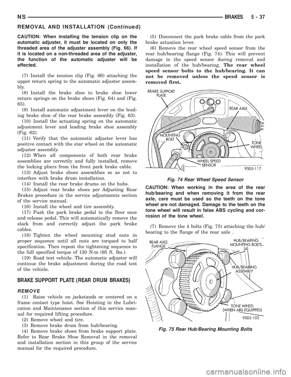
(6) Remove the rear wheel speed sensor from the
rear hub/bearing flange (Fig. 74). This will prevent
damage to the speed sensor during removal and
installation of the hub/bearing.The rear wheel
speed sensor bolts to the hub/bearing. It can
not be removed unless the speed sensor is
removed first.
CAUTION: When working in the area of the rear
hub/bearing and when removing it from the rear
axle, care must be used so the teeth on the tone
wheel are not damaged. Damage to the teeth on the
tone wheel will result in false ABS cycling and cor-
rosion of the tone wheel.
(7) Remove the 4 bolts (Fig. 75) attaching the hub/
bearing to the flange of the rear axle .
Fig. 74 Rear Wheel Speed Sensor
Fig. 75 Rear Hub/Bearing Mounting Bolts
NSBRAKES 5 - 37
REMOVAL AND INSTALLATION (Continued)