tire type CHRYSLER VOYAGER 1996 Owner's Manual
[x] Cancel search | Manufacturer: CHRYSLER, Model Year: 1996, Model line: VOYAGER, Model: CHRYSLER VOYAGER 1996Pages: 1938, PDF Size: 55.84 MB
Page 190 of 1938

INSTALL
CAUTION: Proper installation of wheel speed sen-
sor cables is critical to continued system operation.
Be sure that cables are installed in retainers. Fail-
ure to install cables in retainers as shown in this
section may result in contact with moving parts
and/or over extension of cables, resulting in an
open circuit.
(1) Install wheel speed sensor head. Note, the plas-
tic anti rotation pin must be fully seated prior to
installing the attaching bolt.
CAUTION: Prior to installing the speed sensor
head attaching bolt, the plastic anti-rotation pin
must be fully seated into the bearing flange.
(2) Install the wheel speed sensor head to bearing
flange attaching bolt (Fig. 42). Tighten the attaching
bolt to a torque 12 N´m (105 in. lbs.)
(3) Check the air gap between the face of the
wheel speed sensor and the top surface of the tone-
wheel. Air gap must be less then the maximum
allowable tolerance of 1.2 mm (.047 in.).
(4) Install the 2 routing brackets attaching the
speed sensor cable and brake tube to the rear axle
(Fig. 41).The rear wheel speed sensor cable
should be routed under the rear brake tube
(Fig. 41).
CAUTION: When installing rear wheel speed sen-
sor cable in the routing clips on rear brake flex
hose, be sure not to damage the routing clips.
Routing clips are molded onto the hose and will
require replacement of the brake flex hose if dam-
aged during installation of the wheel speed sensor
cable.(5) Install speed sensor cable into routing clips on
rear brake flex hose (Fig. 41).
(6) If installing a right rear speed sensor cable,
install the speed sensor cable grommet on the axle
brake flex hose bracket (Fig. 40).
CAUTION: The wheel speed sensor cable connec-
tors for the left and right rear wheel speed sensors
are keyed differently. Therefore, when connecting a
wheel speed sensor cable to the vehicle wiring har-
ness, do not force the connectors together. If the
connectors are forced together, damage to the con-
nectors will occur.
(7) Plug speed sensor cable connector into vehicle
wiring harness (Fig. 38).Be sure speed sensor
cable connector is fully seated and locked into
vehicle wiring harness connector.
(8) Install the speed sensor cable grommet into the
body, being sure the grommet is fully seated into the
body hole.
(9) Install the tire and wheel assembly on vehicle.
(10) Road test vehicle to ensure proper operation
of the base and ABS braking systems.
WHEEL SPEED SENSOR (REAR AWD)
REMOVE
(1) Raise vehicle on jack stands or centered on a
frame contact type hoist. See Hoisting in the Lubri-
cation and Maintenance section of this manual, for
the required lifting procedure to be used for this
vehicle.
(2) Remove the tire and wheel assembly from the
vehicle.
CAUTION: When unplugging speed sensor cable
from vehicle wiring harness be careful not to dam-
age pins on the electrical connectors. Also inspect
connectors for any signs of previous damage.
(3) Remove grommet from floor pan of vehicle and
unplug speed sensor cable connector from vehicle
wiring harness (Fig. 43).
CAUTION: When removing rear wheel speed sen-
sor cable from routing clips on rear brake flex hose,
be sure not to damage the routing clips. Routing
clips are molded onto the hose and will require
replacement of the brake flex hose if damaged dur-
ing removal of the speed sensor cable.
Fig. 42 Rear Wheel Speed Sensor Attaching Bolt
5 - 108 BRAKESNS
REMOVAL AND INSTALLATION (Continued)
Page 192 of 1938

(2) Install the wheel speed sensor head attaching
bolt (Fig. 46). Tighten the attaching bolt to a torque
12 N´m (105 in. lbs.)
(3) Check the air gap between the face of the
wheel speed sensor and the top surface of the tone-
wheel. Air gap must be less then the maximum
allowable tolerance of 1.2 mm (.047 in.).
(4) Install the routing brackets attaching the speed
sensor cable and brake tube to the rear axle (Fig.
45).The rear wheel speed sensor cable should
be routed under the rear brake tube (Fig. 45).
CAUTION: When installing rear wheel speed sen-
sor cable in the routing clips on rear brake flex
hose, be sure not to damage the routing clips.
Routing clips are molded onto the hose and will
require replacement of the brake flex hose if dam-
aged during installation of the wheel speed sensor
cable.
(5) Install speed sensor cable into routing clips on
rear brake flex hose (Fig. 44).
CAUTION: The wheel speed sensor cable connec-
tors for the left and right rear wheel speed sensors
are keyed differently. Therefore, when connecting a
wheel speed sensor cable to the vehicle wiring har-
ness, do not force the connectors together. If the
connectors are forced together, damage to the con-
nectors will occur.
(6) Plug speed sensor cable connector into vehicle
wiring harness (Fig. 43).Be sure speed sensor
cable connector is fully seated and locked into
vehicle wiring harness connector.
(7) Install the speed sensor cable grommet into the
body, being sure the grommet is fully seated into the
body hole.
(8) Install the tire and wheel assembly on vehicle.
(9) Road test vehicle to ensure proper operation of
the base and ABS braking systems.
TONE WHEEL (REAR FWD)
REMOVE
(1) Raise vehicle on jackstands or centered on a
frame contact type hoist. See Hoisting in the Lubri-
cation and Maintenance section of this service man-
ual for required lifting procedure.
(2) Remove the wheel and tire assembly.
(3) Remove rear brake drum from the hub/bearing
assembly.
(4) Remove the rear wheel speed sensor from the
rear hub/bearing flange (Fig. 47). This will prevent
damage to the speed sensor during removal and
installation of the hub/bearing assembly.(5) Remove the 4 bolts (Fig. 48) attaching the hub/
bearing assembly to the flange of the rear axle.
(6) Remove the hub/bearing assembly from the
rear axle and brake support plate (Fig. 49).
Fig. 47 Rear Wheel Speed Sensor
Fig. 48 Rear Hub/Bearing Mounting Bolts
Fig. 49 Removing Rear Hub/Bearing From Axle
5 - 110 BRAKESNS
REMOVAL AND INSTALLATION (Continued)
Page 288 of 1938

GENERATOR
The generator is belt-driven by the engine. It is
serviced only as a complete assembly. If the genera-
tor fails for any reason, the entire assembly must be
replaced.
As the energized rotor begins to rotate within the
generator, the spinning magnetic field induces a cur-
rent into the windings of the stator coil. Once the
generator begins producing sufficient current, it also
provides the current needed to energize the rotor.
The Y type stator winding connections deliver the
induced AC current to 3 positive and 3 negative
diodes for rectification. From the diodes, rectified DC
current is delivered to the vehicle electrical system
through the generator, battery, and ground terminals.
Noise emitting from the generator may be caused
by:
²Worn, loose or defective bearings
²Loose or defective drive pulley
²Incorrect, worn, damaged or misadjusted drive
belt
²Loose mounting bolts
²Misaligned drive pulley
²Defective stator or diode
BATTERY TEMPERATURE SENSOR
The temperature sensor, in the PCM, is used to
determine the battery temperature. This temperature
data, along with data from monitored line voltage, is
used by the PCM to vary the battery charging rate.
System voltage will be higher at colder temperatures
and is gradually reduced at warmer temperatures.
ELECTRONIC VOLTAGE REGULATOR
The Electronic Voltage Regulator (EVR) is not a
separate component. It is actually a voltage regulat-
ing circuit located within the Powertrain Control
Module (PCM). The EVR is not serviced separately. If
replacement is necessary, the PCM must be replaced.
Operation:The amount of DC current produced
by the generator is controlled by EVR circuitry con-
tained within the PCM. This circuitry is connected in
series with the generators second rotor field terminal
and its ground.
Voltage is regulated by cycling the ground path to
control the strength of the rotor magnetic field. The
EVR circuitry monitors system line voltage and bat-
tery temperature (refer to Battery Temperature Sen-
sor for more information). It then compensates and
regulates generator current output accordingly. Also
refer to Charging System Operation for additional
information.
DIAGNOSIS AND TESTING
CHARGING SYSTEM
When the ignition switch is turned to the ON posi-
tion, battery potential will register on the voltmeter.
During engine cranking a lower voltage will appear
on the meter. With the engine running, a voltage
reading higher than the first reading (ignition in ON)
should register.
The following are possible symptoms of a charging
system fault:
²The voltmeter does not operate properly
²An undercharged or overcharged battery condi-
tion occurs.
Remember that an undercharged battery is often
caused by:
²Accessories being left on with the engine not
running
²A faulty or improperly adjusted switch that
allows a lamp to stay on. See Ignition-Off Draw Test
in Group 8A, Battery for more information.
The following procedures may be used to correct a
problem diagnosed as a charging system fault.
INSPECTION
(1) Inspect condition of battery cable terminals,
battery posts, connections at engine block, starter
solenoid and relay. They should be clean and tight.
Repair as required.
(2) Inspect all fuses in the fuseblock module and
Power Distribution Center (PDC) for tightness in
receptacles. They should be properly installed and
tight. Repair or replace as required.
(3) Inspect the electrolyte level in the battery.
Replace battery if electrolyte level is low.
(4) Inspect generator mounting bolts for tightness.
Replace or tighten bolts if required. Refer to the Gen-
erator Removal/Installation section of this group for
torque specifications.
(5) Inspect generator drive belt condition and ten-
sion. Tighten or replace belt as required. Refer to
Belt Tension Specifications in Group 7, Cooling Sys-
tem.
(6) Inspect automatic belt tensioner (if equipped).
Refer to Group 7, Cooling System for information.
(7) Inspect connections at generator field, battery
output, and ground terminals. Also check ground con-
nection at engine. They should all be clean and tight.
Repair as required.
8C - 2 CHARGING SYSTEMNS
DESCRIPTION AND OPERATION (Continued)
Page 574 of 1938
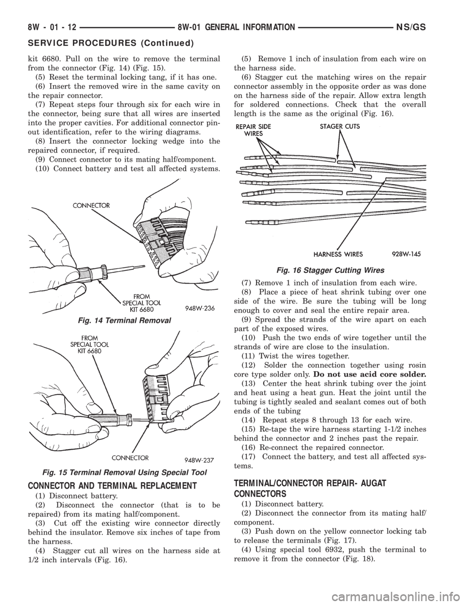
kit 6680. Pull on the wire to remove the terminal
from the connector (Fig. 14) (Fig. 15).
(5) Reset the terminal locking tang, if it has one.
(6) Insert the removed wire in the same cavity on
the repair connector.
(7) Repeat steps four through six for each wire in
the connector, being sure that all wires are inserted
into the proper cavities. For additional connector pin-
out identification, refer to the wiring diagrams.
(8) Insert the connector locking wedge into the
repaired connector, if required.
(9)
Connect connector to its mating half/component.
(10) Connect battery and test all affected systems.
CONNECTOR AND TERMINAL REPLACEMENT
(1) Disconnect battery.
(2) Disconnect the connector (that is to be
repaired) from its mating half/component.
(3) Cut off the existing wire connector directly
behind the insulator. Remove six inches of tape from
the harness.
(4) Stagger cut all wires on the harness side at
1/2 inch intervals (Fig. 16).(5) Remove 1 inch of insulation from each wire on
the harness side.
(6) Stagger cut the matching wires on the repair
connector assembly in the opposite order as was done
on the harness side of the repair. Allow extra length
for soldered connections. Check that the overall
length is the same as the original (Fig. 16).
(7) Remove 1 inch of insulation from each wire.
(8) Place a piece of heat shrink tubing over one
side of the wire. Be sure the tubing will be long
enough to cover and seal the entire repair area.
(9) Spread the strands of the wire apart on each
part of the exposed wires.
(10) Push the two ends of wire together until the
strands of wire are close to the insulation.
(11) Twist the wires together.
(12) Solder the connection together using rosin
core type solder only.Do not use acid core solder.
(13) Center the heat shrink tubing over the joint
and heat using a heat gun. Heat the joint until the
tubing is tightly sealed and sealant comes out of both
ends of the tubing
(14) Repeat steps 8 through 13 for each wire.
(15) Re-tape the wire harness starting 1-1/2 inches
behind the connector and 2 inches past the repair.
(16) Re-connect the repaired connector.
(17) Connect the battery, and test all affected sys-
tems.
TERMINAL/CONNECTOR REPAIR- AUGAT
CONNECTORS
(1) Disconnect battery.
(2) Disconnect the connector from its mating half/
component.
(3) Push down on the yellow connector locking tab
to release the terminals (Fig. 17).
(4) Using special tool 6932, push the terminal to
remove it from the connector (Fig. 18).
Fig. 14 Terminal Removal
Fig. 15 Terminal Removal Using Special Tool
Fig. 16 Stagger Cutting Wires
8W - 01 - 12 8W-01 GENERAL INFORMATIONNS/GS
SERVICE PROCEDURES (Continued)
Page 576 of 1938
(9) Place a piece of heat shrink tubing over one
side of the wire. Make sure the tubing will be long
enough to cover and seal the entire repair area.
(10) Spread the strands of the wire apart on each
part of the exposed wires.
(11) Push the two ends of wire together until the
strands of wire are close to the insulation.
(12) Twist the wires together.
(13) Solder the connection together using rosin
core type solder only.Do not use acid core solder.
(14) Center the heat shrink tubing over the joint
and heat using a heat gun. Heat the joint until the
tubing is tightly sealed and sealant comes out of both
ends of the tubing.
(15) Insert the repaired wire into the connector.
(16) Install the connector locking wedge, if
required, and reconnect the connector to its mating
half/component.
(17) Re-tape the wire harness starting 1-1/2 inches
behind the connector and 2 inches past the repair.
(18) Connect battery, and test all affected systems.
DIODE REPLACEMENT
(1) Disconnect the battery.
(2) Locate the diode in the harness, and remove
the protective covering.
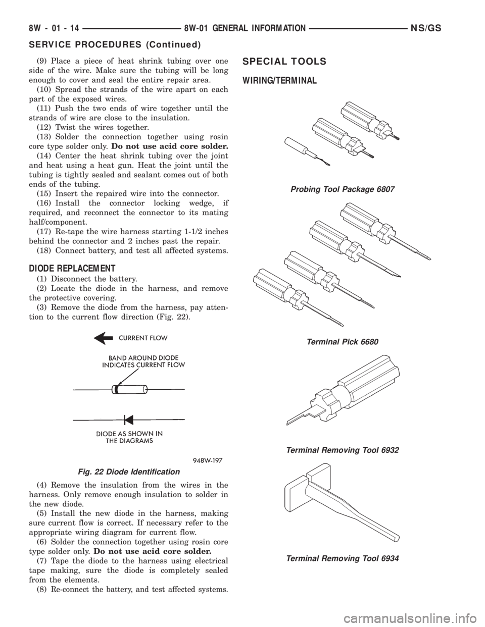
(3) Remove the diode from the harness, pay atten-
tion to the current flow direction (Fig. 22).
(4) Remove the insulation from the wires in the
harness. Only remove enough insulation to solder in
the new diode.
(5) Install the new diode in the harness, making
sure current flow is correct. If necessary refer to the
appropriate wiring diagram for current flow.
(6) Solder the connection together using rosin core
type solder only.Do not use acid core solder.
(7) Tape the diode to the harness using electrical
tape making, sure the diode is completely sealed
from the elements.
(8)
Re-connect the battery, and test affected systems.
SPECIAL TOOLS
WIRING/TERMINAL
Fig. 22 Diode Identification
Probing Tool Package 6807
Terminal Pick 6680
Terminal Removing Tool 6932
Terminal Removing Tool 6934
8W - 01 - 14 8W-01 GENERAL INFORMATIONNS/GS
SERVICE PROCEDURES (Continued)
Page 1375 of 1938
leaks are not present. The component should be
replaced immediately if there is any evidence of deg-
radation that could result in failure.
Never attempt to repair a plastic fuel line/tube or a
quick±connect fitting. Replace complete line/tube as
necessary.
Avoid contact of any fuel tubes/hoses with other
vehicle components that could cause abrasions or
scuffing. Be sure that the fuel lines/tubes are prop-
erly routed to prevent pinching and to avoid heat
sources.
The lines/tubes/hoses are of a special construction.
If it is necessary to replace these lines/tubes/hoses,
use only original equipment type.
The hose clamps used to secure the rubber hoses
are of a special rolled edge construction. This con-
struction is used to prevent the edge of the clamp
from cutting into the hose. Only these rolled edge
type clamps may be used in this system. All other
types of clamps may cut into the hoses and cause
fuel leaks.
Where a rubber hose is joined to a metal tube
(staked), do not attempt to repair. Replace entire
line/tube assembly.
Use new original equipment type hose clamps.
Tighten hose clamps to 2 N´m (20 in. lbs.) torque.
QUICK-CONNECT FITTINGSÐLOW PRESSURE
TYPE
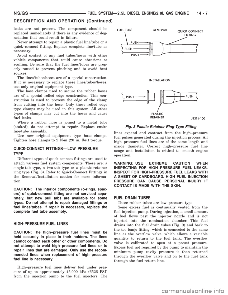
Different types of quick-connect fittings are used to
attach various fuel system components. These are: a
single-tab type, a two-tab type or a plastic retainer
ring type (Fig. 8). Refer to Quick-Connect Fittings in
the Removal/Installation section for more informa-
tion.
CAUTION: The interior components (o-rings, spac-
ers) of quick-connect fitting are not serviced sepa-
rately, but new pull tabs are available for some
types. Do not attempt to repair damaged fittings or
fuel lines/tubes. If repair is necessary, replace the
complete fuel tube assembly.
HIGH-PRESSURE FUEL LINES
CAUTION: The high±pressure fuel lines must be
held securely in place in their holders. The lines
cannot contact each other or other components. Do
not attempt to weld high±pressure fuel lines or to
repair lines that are damaged. Only use the recom-
mended lines when replacement of high±pressure
fuel line is necessary.
High±pressure fuel lines deliver fuel under pres-
sure of up to approximately 45,000 kPa (6526 PSI)
from the injection pump to the fuel injectors. Thelines expand and contract from the high±pressure
fuel pulses generated during the injection process. All
high±pressure fuel lines are of the same length and
inside diameter. Correct high±pressure fuel line
usage and installation is critical to smooth engine
operation.
WARNING: USE EXTREME CAUTION WHEN
INSPECTING FOR HIGH±PRESSURE FUEL LEAKS.
INSPECT FOR HIGH±PRESSURE FUEL LEAKS WITH
A SHEET OF CARDBOARD. HIGH FUEL INJECTION
PRESSURE CAN CAUSE PERSONAL INJURY IF
CONTACT IS MADE WITH THE SKIN.
FUEL DRAIN TUBES
These rubber tubes are low±pressure type.
Some excess fuel is continually vented from the
fuel injection pump. During injection, a small amount
of fuel flows past the injector nozzle and is not
injected into the combustion chamber. This fuel
drains into the fuel drain tubes (Fig. 9) and back to
the tee banjo fitting, which is connected to the same
line as the overflow valve, which allows a variable
quantity to return to the fuel tank. The overflow
valve is calibrated to open at a preset pressure.
Excess fuel not required by the pump to maintain the
minimum pump cavity pressure is then returned
through the overflow valve and on to the fuel tank
through the fuel return line.
Fig. 8 Plastic Retainer Ring-Type Fitting
NS/GSFUEL SYSTEMÐ2.5L DIESEL ENGINE/2.0L GAS ENGINE 14 - 7
DESCRIPTION AND OPERATION (Continued)
Page 1439 of 1938
(18) Remove the 3 previously loosened bolts
attaching the front bracket to the power steering
pump and separate the power steering pump from
the front bracket prior to removing the pump from
the vehicle.
(19) The power steering pump is removed from the
vehicle by pulling it out through the exhaust tunnel
area in the floor pan of the vehicle.
INSTALL
(1) Install power steering pump back in vehicle
using the reverse order of its removal through the
exhaust tunnel are of the vehicle.
(2) Install the power steering pump on its cast
mounting bracket and loosely install nut to hold
pump in place (Fig. 9).
(3) Install the front bracket on the power steering
pump and loosely install the 3 mounting bolts (Fig.
10). Then install the nut and bolt attaching the front
bracket to the cast bracket (Fig. 10).
(4) Tighten the 3 power steering pump mounting
bolts (Fig. 10) to a torque of 54 N´m (40 ft. lbs.).
NOTE: Before installing power steering fluid pres-
sure hose on power steering pump, inspect the
O-ring on the pressure hose for damage and
replace if necessary.
(5) Install the power steering fluid pressure line
onto the output fitting of the power steering pump
(Fig. 8). Tighten the pressure line to pump fitting
tube nut to a torque of 31 N´m (275 in. lbs.).
(6) Install the power steering fluid, low pressure
return hose on the power steering pump low pressure
fitting (Fig. 8).Be sure hose clamps are properly
reinstalled.
(7) Install the power steering fluid supply hose
from the power steering fluid reservoir, on the power
steering pump fluid fitting (Fig. 7).Be sure hose is
clear of accessory drive belts all hose clamps
are properly reinstalled.
(8) Install the power steering pump drive belt on
pulley. See Cooling, Group 7 for detailed installation
procedure.
(9) Install the accessory drive splash shield (Fig.
6).
(10) Install the power steering fluid return hose on
the steel tube at the front suspension cradle (Fig. 5).
(11) Install a screw type hose clamp on the power
steering hose to steel tube connection.Be sure hose
clamps are properly reinstalled.Tighten the screw
clamp to a torque of 2 N´m (18 in. lbs.).
CAUTION: The protective heat shield sleeves must
cover the entire rubber hose and hose to tube con-
nection portion of both the power steering fluid
pressure and return hoses (Fig. 5). This is requiredto prevent the overheating of the power steering
hoses.
(12) When used, properly position the protective
heat sleeves on the power steering hoses (Fig. 5).
Then, tie strap the heat sleeves to the power steering
hoses to keep them in their proper position.
(13) Install the exhaust pipe on the exhaust man-
ifold. Install all exhaust system hangers/isolators on
the exhaust system brackets.
(14) Connect the oxygen sensor wiring harness to
the vehicle wiring harness. Install wiring harness
grommet in the floor pan of the vehicle.
(15) Lower vehicle.
(16) Adjust the power steering pump drive belt.
See Cooling, Group 7 for detailed adjustment proce-
dure.
(17) Tighten the top nut and bottom bolt on the
power steering pump front mounting bracket (Fig. 3)
to a torque of 54 N´m (40 ft. lbs.).
CAUTION: Do not use automatic transmission fluid
in power steering system. Only use MoparT, Power
Steering Fluid, or equivalent.
(18) Fill the remote power steering pump fluid res-
ervoir to correct fluid level.
(19) Install cap on power steering fluid reservoir.
(20) Connect the negative battery cable on the
negative battery post.
(21) Start engine and turn steering wheel several
times from stop to stop to bleed air from fluid in sys-
tem. Stop engine, check fluid level, and inspect sys-
tem for leaks. See Checking Fluid Level.
3.0 LITER POWER STEERING PUMP
REMOVE
WARNING: POWER STEERING OIL, ENGINE COM-
PONENTS AND THE EXHAUST SYSTEM MAY BE
EXTREMELY HOT IF ENGINE HAS BEEN RUNNING.
DO NOT START ENGINE WITH ANY LOOSE OR DIS-
CONNECTED HOSES. DO NOT ALLOW HOSES TO
TOUCH HOT EXHAUST MANIFOLD OR CATALYST.
(1) Remove the (-) negative battery cable from the
battery and isolate cable.
(2) Remove cap from power steering fluid reser-
voir.
(3) Using a siphon pump, remove as much power
steering fluid as possible from the power steering
fluid reservoir.
NSSTEERING 19 - 13
REMOVAL AND INSTALLATION (Continued)
Page 1441 of 1938
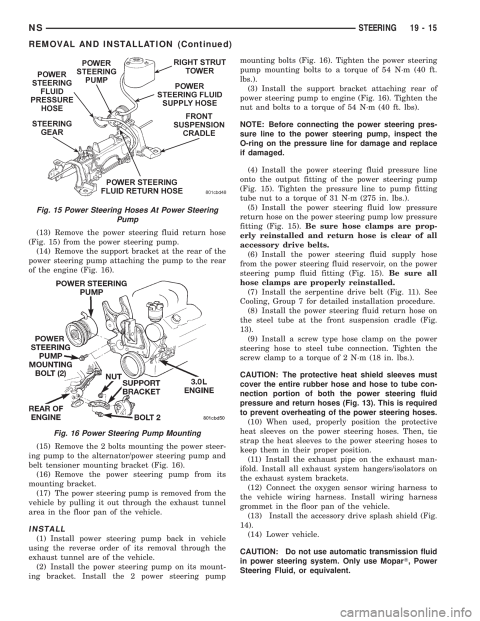
(13) Remove the power steering fluid return hose
(Fig. 15) from the power steering pump.
(14) Remove the support bracket at the rear of the
power steering pump attaching the pump to the rear
of the engine (Fig. 16).
(15) Remove the 2 bolts mounting the power steer-
ing pump to the alternator/power steering pump and
belt tensioner mounting bracket (Fig. 16).
(16) Remove the power steering pump from its
mounting bracket.
(17) The power steering pump is removed from the
vehicle by pulling it out through the exhaust tunnel
area in the floor pan of the vehicle.
INSTALL
(1) Install power steering pump back in vehicle
using the reverse order of its removal through the
exhaust tunnel are of the vehicle.
(2) Install the power steering pump on its mount-
ing bracket. Install the 2 power steering pumpmounting bolts (Fig. 16). Tighten the power steering
pump mounting bolts to a torque of 54 N´m (40 ft.
lbs.).
(3) Install the support bracket attaching rear of
power steering pump to engine (Fig. 16). Tighten the
nut and bolts to a torque of 54 N´m (40 ft. lbs).
NOTE: Before connecting the power steering pres-
sure line to the power steering pump, inspect the
O-ring on the pressure line for damage and replace
if damaged.
(4) Install the power steering fluid pressure line
onto the output fitting of the power steering pump
(Fig. 15). Tighten the pressure line to pump fitting
tube nut to a torque of 31 N´m (275 in. lbs.).
(5) Install the power steering fluid low pressure
return hose on the power steering pump low pressure
fitting (Fig. 15).Be sure hose clamps are prop-
erly reinstalled and return hose is clear of all
accessory drive belts.
(6) Install the power steering fluid supply hose
from the power steering fluid reservoir, on the power
steering pump fluid fitting (Fig. 15).Be sure all
hose clamps are properly reinstalled.
(7) Install the serpentine drive belt (Fig. 11). See
Cooling, Group 7 for detailed installation procedure.
(8) Install the power steering fluid return hose on
the steel tube at the front suspension cradle (Fig.
13).
(9) Install a screw type hose clamp on the power
steering hose to steel tube connection. Tighten the
screw clamp to a torque of 2 N´m (18 in. lbs.).
CAUTION: The protective heat shield sleeves must
cover the entire rubber hose and hose to tube con-
nection portion of both the power steering fluid
pressure and return hoses (Fig. 13). This is required
to prevent overheating of the power steering hoses.
(10) When used, properly position the protective
heat sleeves on the power steering hoses. Then, tie
strap the heat sleeves to the power steering hoses to
keep them in their proper position.
(11) Install the exhaust pipe on the exhaust man-
ifold. Install all exhaust system hangers/isolators on
the exhaust system brackets.
(12) Connect the oxygen sensor wiring harness to
the vehicle wiring harness. Install wiring harness
grommet in the floor pan of the vehicle.
(13) Install the accessory drive splash shield (Fig.
14).
(14) Lower vehicle.
CAUTION: Do not use automatic transmission fluid
in power steering system. Only use MoparT, Power
Steering Fluid, or equivalent.
Fig. 15 Power Steering Hoses At Power Steering
Pump
Fig. 16 Power Steering Pump Mounting
NSSTEERING 19 - 15
REMOVAL AND INSTALLATION (Continued)
Page 1444 of 1938
NOTE: Before installing power steering pressure
hose on power steering pump, inspect the O-ring
on the power steering pressure hose for damage
and replace if required.
(4) Install the power steering fluid pressure line
onto the output fitting of the power steering pump
(Fig. 21). Tighten the pressure line to pump fitting
tube nut to a torque of 31 N´m (275 in. lbs.).
(5) Install the power steering fluid, low pressure
return hose on the power steering pump low pressure
fitting (Fig. 21).Be sure hose clamps are prop-
erly reinstalled.
(6) Install the power steering fluid supply hose
from the power steering fluid reservoir, on the power
steering pump fluid fitting (Fig. 21).Be sure hose is
clear of accessory drive belts and all hose
clamps are properly reinstalled.
(7) Install the serpentine drive belt (Fig. 20). See
Cooling, Group 7 for detailed installation procedure.
(8) Install the power steering fluid return hose on
the steel tube at the front suspension cradle (Fig.
18).
(9) Install a screw type hose clamp on the power
steering hose to steel tube connection.Be sure hose
clamps are properly reinstalled.Tighten the screw
clamp to a torque of 2 N´m (18 in. lbs.).
CAUTION: The protective heat shield sleeves must
cover the entire rubber hose and hose to tube con-
nection portion of both the power steering fluid
pressure and return hoses (Fig. 18). This is required
to keep the power steering hoses from becoming
overheated.
(10) When used, properly position the protective
heat sleeves on the power steering hoses (Fig. 18).
Then, tie strap the heat sleeves to the power steering
hoses to keep them in their proper position.
(11) Install the exhaust pipe on the exhaust man-
ifold. Install all exhaust system hangers/isolators on
the exhaust system brackets.
(12) Connect the oxygen sensor wiring harness to
the vehicle wiring harness. Install wiring harness
grommet in the floor pan of the vehicle.
(13) Install the accessory drive splash shield (Fig.
19).
(14) Lower vehicle.
CAUTION: Do not use automatic transmission fluid
in power steering system. Only use MoparT, Power
Steering Fluid, or equivalent.
(15) Fill the remote power steering pump fluid res-
ervoir to correct fluid level.
(16) Install cap on power steering fluid reservoir.(17) Connect the negative battery cable on the
negative battery post.
(18) Start engine and turn steering wheel several
times from stop to stop to bleed air from fluid in sys-
tem. Stop engine, check fluid level, and inspect sys-
tem for leaks. See Checking Fluid Level.
POWER STEERING FLUID RESERVOIR TO PUMP
SUPPLY HOSE
REMOVE
(1) Remove the filler cap from remote power steer-
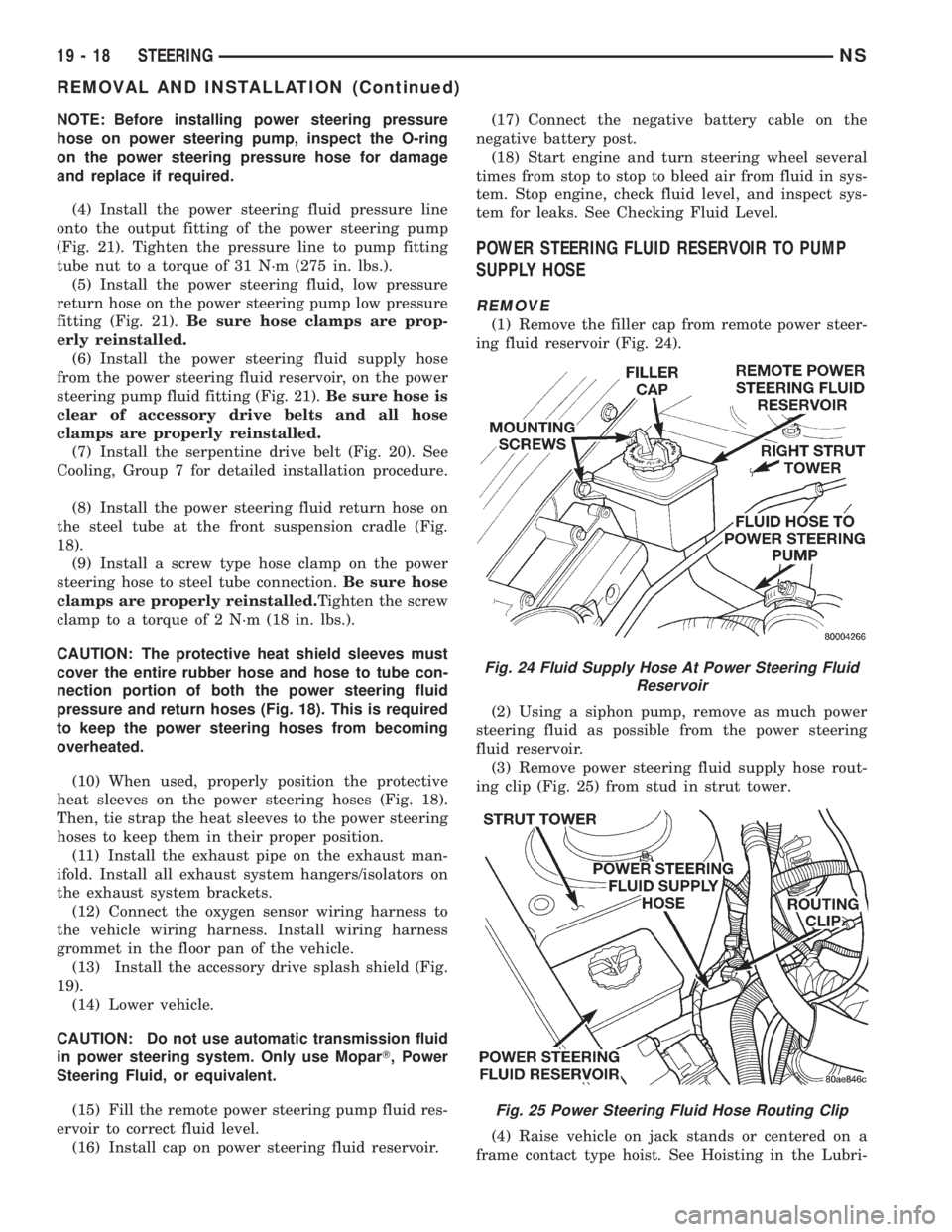
ing fluid reservoir (Fig. 24).
(2) Using a siphon pump, remove as much power
steering fluid as possible from the power steering
fluid reservoir.
(3) Remove power steering fluid supply hose rout-
ing clip (Fig. 25) from stud in strut tower.
(4) Raise vehicle on jack stands or centered on a
frame contact type hoist. See Hoisting in the Lubri-
Fig. 24 Fluid Supply Hose At Power Steering Fluid
Reservoir
Fig. 25 Power Steering Fluid Hose Routing Clip
19 - 18 STEERINGNS
REMOVAL AND INSTALLATION (Continued)
Page 1447 of 1938
(6) Install the power steering fluid return hose on
the steel tube at the front suspension cradle (Fig.
26).
(7) Install a screw type hose clamp on the power
steering hose to steel tube connection. Tighten the
screw clamp to a torque of 2 N´m (18 in. lbs.).
CAUTION: The protective heat sleeves must cover
the entire rubber hose and hose to tube connection
portion of both the power steering fluid pressure
and return hoses (Fig. 26).
(8) When used, properly position the protective
heat sleeves on the power steering hoses. Then, tie
strap the heat sleeves to the power steering hoses to
keep them in their proper position.
(9) After hoses are installed and power steering
system is filled with fluid and cap is installed on res-
ervoir. Start the engine and check for leaks. (See
Pump Installation).
POWER STEERING FLUID RETURN HOSE
Service all power steering hoses with vehicle raised
on hoist. Cap all open ends of hoses, power steering
pump fittings and steering gear ports to prevent
entry of foreign material into the components.
WARNING: POWER STEERING OIL, ENGINE
PARTS AND THE EXHAUST SYSTEM MAY BE
EXTREMELY HOT IF ENGINE HAS BEEN RUNNING.
DO NOT START ENGINE WITH ANY LOOSE OR DIS-
CONNECTED HOSES. DO NOT ALLOW HOSES TO
TOUCH HOT EXHAUST MANIFOLD OR CATALYST.
For part reference and part location for the vehicle
that is being serviced, refer to the following figure
numbers. These show the hose bracket locations,
hose routings and fitting locations by the engine
application of the vehicle. Use these figure numbers
when referring to the removal or installation proce-
dures for the power steering hoses listed below.
REMOVE
(1) Remove cap from power steering fluid reser-
voir.
(2) Using a siphon pump, remove as much power
steering fluid as possible from the power steering
fluid reservoir.
(3) Raise vehicle See Hoisting, Group 0. Put oil
drain pan under vehicle to catch power steering fluid.
(4) Raise the insulating heat sleeve on the power
steering hoses to expose the hose to steel tube con-
nection. Remove hose clamp where rubber portion of
power steering fluid return hose attaches to steel
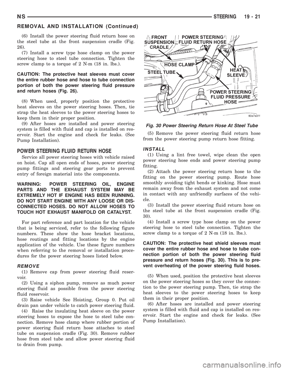
tube on suspension cradle (Fig. 30). Remove rubber
hose from steel tube and allow power steering fluid
to drain from pump.(5) Remove the power steering fluid return hose
from the power steering pump return hose fitting.
INSTALL
(1) Using a lint free towel, wipe clean the open
power steering hose ends and power steering pump
fitting.
(2) Attach the power steering return hose to the
fitting on the power steering pump. Route hose
smoothly avoiding tight bends or kinking. Hose must
remain away from the exhaust system and not come
in contact with any unfriendly surfaces of the vehi-
cle.
(3) Install the power steering fluid return hose on
the steel tube at the front suspension cradle (Fig.
30).
(4) Install a screw type hose clamp on the power
steering hose to steel tube connection. Tighten the
screw clamp to a torque of 2 N´m (18 in. lbs.).
CAUTION: The protective heat shield sleeves must
cover the entire rubber hose and hose to tube con-
nection portion of both the power steering fluid
pressure and return hoses (Fig. 30). This is to pre-
vent overheating of the power steering fluid hoses.
(5) When used, position the protective heat sleeves
on the power steering hoses so they cover the connec-
tion to the power steering pump. Then, tie strap the
heat sleeves to the power steering hoses to keep
them in their proper position.
(6) After hoses are installed and power steering
system is filled with fluid and cap is installed on res-
ervoir. Start the engine and check for leaks. (See
Pump Installation).
Fig. 30 Power Steering Return Hose At Steel Tube
NSSTEERING 19 - 21
REMOVAL AND INSTALLATION (Continued)