compression ratio CHRYSLER VOYAGER 1996 Service Manual
[x] Cancel search | Manufacturer: CHRYSLER, Model Year: 1996, Model line: VOYAGER, Model: CHRYSLER VOYAGER 1996Pages: 1938, PDF Size: 55.84 MB
Page 72 of 1938
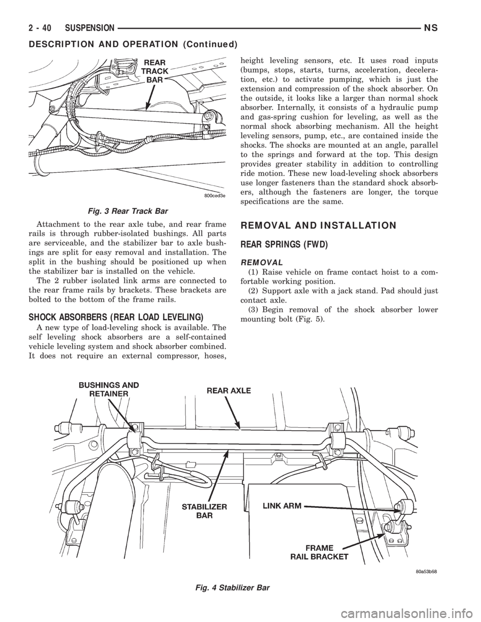
Attachment to the rear axle tube, and rear frame
rails is through rubber-isolated bushings. All parts
are serviceable, and the stabilizer bar to axle bush-
ings are split for easy removal and installation. The
split in the bushing should be positioned up when
the stabilizer bar is installed on the vehicle.
The 2 rubber isolated link arms are connected to
the rear frame rails by brackets. These brackets are
bolted to the bottom of the frame rails.
SHOCK ABSORBERS (REAR LOAD LEVELING)
A new type of load-leveling shock is available. The
self leveling shock absorbers are a self-contained
vehicle leveling system and shock absorber combined.
It does not require an external compressor, hoses,height leveling sensors, etc. It uses road inputs
(bumps, stops, starts, turns, acceleration, decelera-
tion, etc.) to activate pumping, which is just the
extension and compression of the shock absorber. On
the outside, it looks like a larger than normal shock
absorber. Internally, it consists of a hydraulic pump
and gas-spring cushion for leveling, as well as the
normal shock absorbing mechanism. All the height
leveling sensors, pump, etc., are contained inside the
shocks. The shocks are mounted at an angle, parallel
to the springs and forward at the top. This design
provides greater stability in addition to controlling
ride motion. These new load-leveling shock absorbers
use longer fasteners than the standard shock absorb-
ers, although the fasteners are longer, the torque
specifications are the same.
REMOVAL AND INSTALLATION
REAR SPRINGS (FWD)
REMOVAL
(1) Raise vehicle on frame contact hoist to a com-
fortable working position.
(2) Support axle with a jack stand. Pad should just
contact axle.
(3) Begin removal of the shock absorber lower
mounting bolt (Fig. 5).
Fig. 4 Stabilizer Bar
Fig. 3 Rear Track Bar
2 - 40 SUSPENSIONNS
DESCRIPTION AND OPERATION (Continued)
Page 107 of 1938
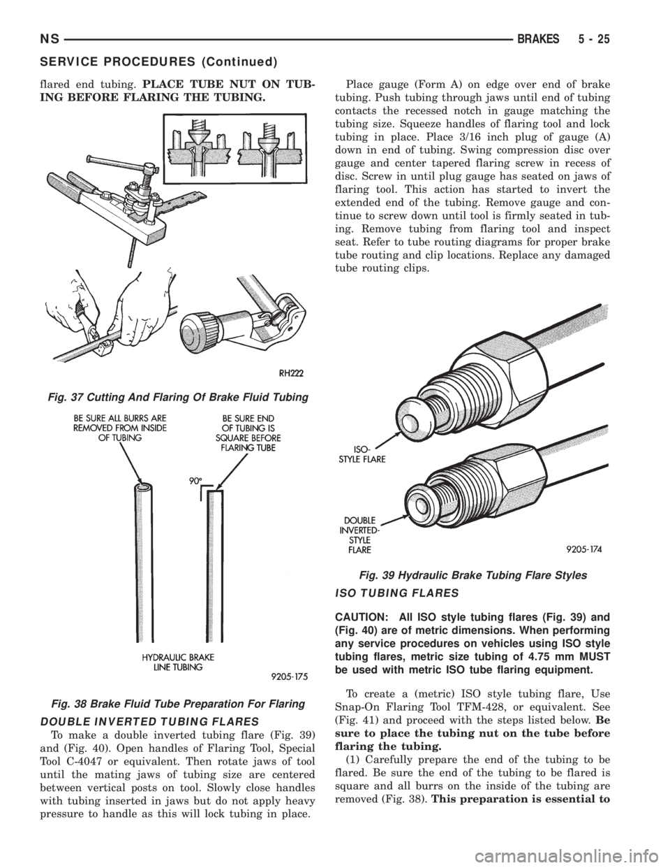
flared end tubing.PLACE TUBE NUT ON TUB-
ING BEFORE FLARING THE TUBING.
DOUBLE INVERTED TUBING FLARES
To make a double inverted tubing flare (Fig. 39)
and (Fig. 40). Open handles of Flaring Tool, Special
Tool C-4047 or equivalent. Then rotate jaws of tool
until the mating jaws of tubing size are centered
between vertical posts on tool. Slowly close handles
with tubing inserted in jaws but do not apply heavy
pressure to handle as this will lock tubing in place.Place gauge (Form A) on edge over end of brake
tubing. Push tubing through jaws until end of tubing
contacts the recessed notch in gauge matching the
tubing size. Squeeze handles of flaring tool and lock
tubing in place. Place 3/16 inch plug of gauge (A)
down in end of tubing. Swing compression disc over
gauge and center tapered flaring screw in recess of
disc. Screw in until plug gauge has seated on jaws of
flaring tool. This action has started to invert the
extended end of the tubing. Remove gauge and con-
tinue to screw down until tool is firmly seated in tub-
ing. Remove tubing from flaring tool and inspect
seat. Refer to tube routing diagrams for proper brake
tube routing and clip locations. Replace any damaged
tube routing clips.
ISO TUBING FLARES
CAUTION: All ISO style tubing flares (Fig. 39) and
(Fig. 40) are of metric dimensions. When performing
any service procedures on vehicles using ISO style
tubing flares, metric size tubing of 4.75 mm MUST
be used with metric ISO tube flaring equipment.
To create a (metric) ISO style tubing flare, Use
Snap-On Flaring Tool TFM-428, or equivalent. See
(Fig. 41) and proceed with the steps listed below.Be
sure to place the tubing nut on the tube before
flaring the tubing.
(1) Carefully prepare the end of the tubing to be
flared. Be sure the end of the tubing to be flared is
square and all burrs on the inside of the tubing are
removed (Fig. 38).This preparation is essential to
Fig. 37 Cutting And Flaring Of Brake Fluid Tubing
Fig. 38 Brake Fluid Tube Preparation For Flaring
Fig. 39 Hydraulic Brake Tubing Flare Styles
NSBRAKES 5 - 25
SERVICE PROCEDURES (Continued)
Page 302 of 1938
Clean Spark Plug cables with a cloth moistened
with a non-flammable solvent. Wipe the cables dry.
Check for brittle or cracked insulation.
SPARK PLUG CABLESÐ3.3/3.8L
The spark plug cables and spark plug boots are
made from high temperature silicone materials. The
spark plug boots utilize metal heat shields for ther-
mal protection from the exhaust manifold. The heat
shields slide over the spark plug boots. The notches
on the heat shields ensure the spark plug boot and
shield twist together during spark plug boot removal.
They also identify proper heat shield installation on
the boot for service.Refer to 3.3/3.8L Spark Plug
Cable removal and installation.All spark plug
cable leads are properly identified with cylinder num-
bers. The inside of the spark plug boot is coated with
a special high temperature silicone grease for greater
sealing and to minimize boot bonding to the spark
plug insulator. The convoluted tubing on the rear
plug cables are made of a high temperature plastic
material. Under normal driving conditions, the spark
plug cables have a recommended service life of a
100,000 miles. The spark plugs have a recommended
service life of 75,000 miles for severe driving condi-
tions per schedule B in this manual.
The spark plug heat shield can be reused if an
ignition cable is replaced due to failure. Never reuse
heat shield's that have heat shield anti-twist, side or
spark plug attachment tabs bent or missing. Ensure
that the heat shield is properly attached to the spark
plug to avoid RFI problems. The bottom of the spark
plug heat shield must make contact with the spark
plug hex.
The front ignition cables must not make contact
with the oil dip stick tube and #5 cable must not
touch the coil mounting bolt to avoid abrasion/dielec-
tric failures.
IGNITION COIL
WARNING: THE DIRECT IGNITION SYSTEM GEN-
ERATES APPROXIMATELY 40,000 VOLTS. PER-
SONAL INJURY COULD RESULT FROM CONTACT
WITH THIS SYSTEM.
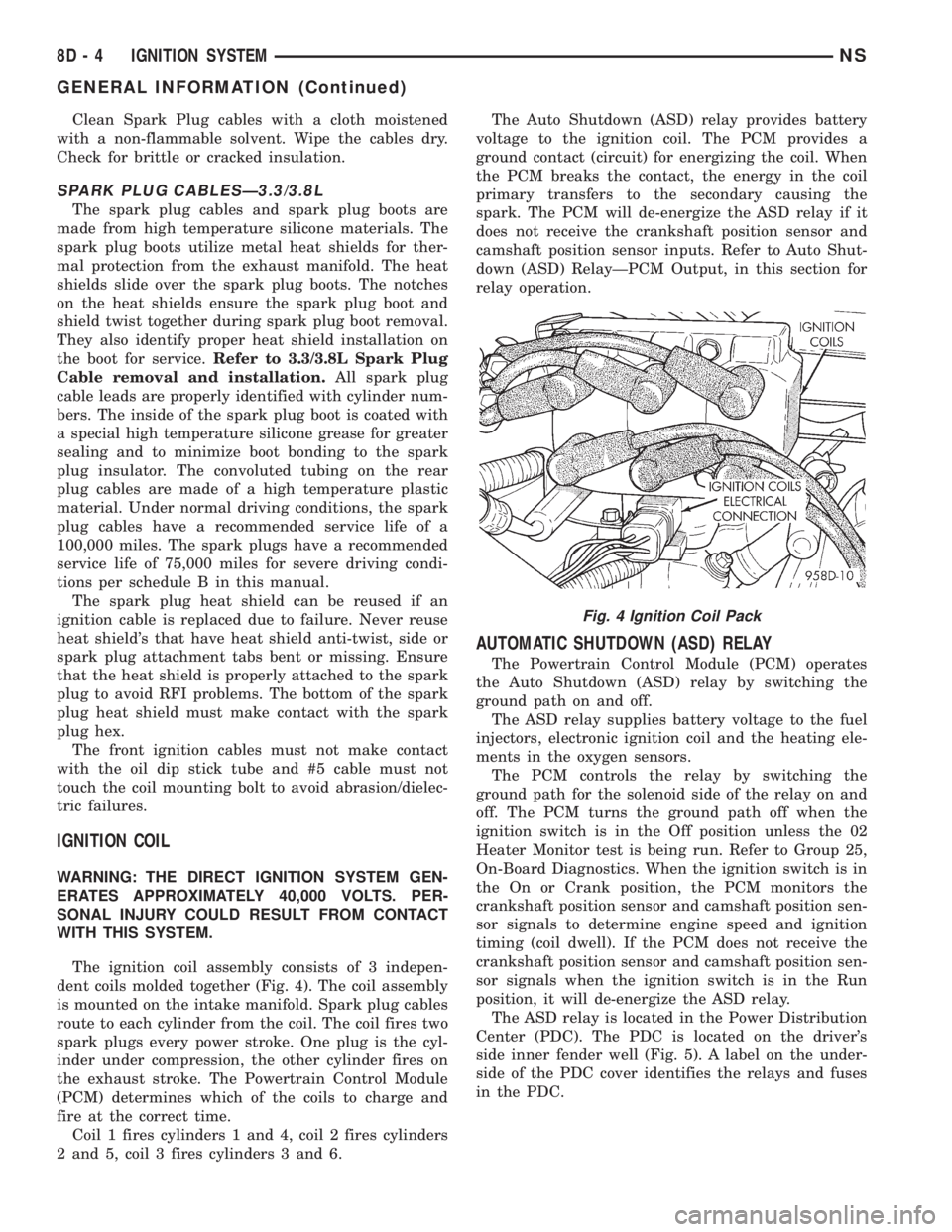
The ignition coil assembly consists of 3 indepen-
dent coils molded together (Fig. 4). The coil assembly
is mounted on the intake manifold. Spark plug cables
route to each cylinder from the coil. The coil fires two
spark plugs every power stroke. One plug is the cyl-
inder under compression, the other cylinder fires on
the exhaust stroke. The Powertrain Control Module
(PCM) determines which of the coils to charge and
fire at the correct time.
Coil 1 fires cylinders 1 and 4, coil 2 fires cylinders
2 and 5, coil 3 fires cylinders 3 and 6.The Auto Shutdown (ASD) relay provides battery
voltage to the ignition coil. The PCM provides a
ground contact (circuit) for energizing the coil. When
the PCM breaks the contact, the energy in the coil
primary transfers to the secondary causing the
spark. The PCM will de-energize the ASD relay if it
does not receive the crankshaft position sensor and
camshaft position sensor inputs. Refer to Auto Shut-
down (ASD) RelayÐPCM Output, in this section for
relay operation.
AUTOMATIC SHUTDOWN (ASD) RELAY
The Powertrain Control Module (PCM) operates
the Auto Shutdown (ASD) relay by switching the
ground path on and off.
The ASD relay supplies battery voltage to the fuel
injectors, electronic ignition coil and the heating ele-
ments in the oxygen sensors.
The PCM controls the relay by switching the
ground path for the solenoid side of the relay on and
off. The PCM turns the ground path off when the
ignition switch is in the Off position unless the 02
Heater Monitor test is being run. Refer to Group 25,
On-Board Diagnostics. When the ignition switch is in
the On or Crank position, the PCM monitors the
crankshaft position sensor and camshaft position sen-
sor signals to determine engine speed and ignition
timing (coil dwell). If the PCM does not receive the
crankshaft position sensor and camshaft position sen-
sor signals when the ignition switch is in the Run
position, it will de-energize the ASD relay.
The ASD relay is located in the Power Distribution
Center (PDC). The PDC is located on the driver's
side inner fender well (Fig. 5). A label on the under-
side of the PDC cover identifies the relays and fuses
in the PDC.
Fig. 4 Ignition Coil Pack
8D - 4 IGNITION SYSTEMNS
GENERAL INFORMATION (Continued)
Page 1052 of 1938
made to seal the area between the bedplate and cyl-
inder block without disturbing the bearing clearance
or alignment of these components.
GASKET DISASSEMBLY
Parts assembled with form-in-place gaskets may be
disassembled without unusual effort. In some
instances, it may be necessary to lightly tap the part
with a mallet or other suitable tool to break the seal
between the mating surfaces. A flat gasket scraper
may also be lightly tapped into the joint but care
must be taken not to damage the mating surfaces.
SURFACE PREPARATION
Scrape clean or wire brush all gasket surfaces to
remove all loose material. Inspect stamped parts to
ensure gasket rails are flat. Gasket surfaces must be
free of oil and dirt. Make sure old gasket material is
removed from blind attaching holes.
FORM-IN-PLACE GASKET APPLICATION
Assembling parts using a form-in-place gasket
requires care but it's easier then using precut gas-
kets.
MopartGasket Maker material should be applied
sparingly 1 mm (0.040 in.) diameter or less of sealant
to one gasket surface. Be certain the material sur-
rounds each mounting hole. Excess material can eas-
ily be wiped off. Components should be torqued in
place within 15 minutes. The use of a locating dowel
is recommended during assembly to prevent smear-
ing the material off location.
TheMopartSilicone Rubber Adhesive Sealant
gasket material or equivalent should be applied in a
continuous bead approximately 3 mm (0.120 in.) in
diameter. All mounting holes must be circled. For
corner sealing, a 3.17 or 6.35 mm (1/8 or 1/4 in.) drop
is placed in the center of the gasket contact area.
Uncured sealant may be removed with a shop towels.
Components should be torqued in place while the
sealant is still wet to the touch (within 10 minutes).
The usage of a locating dowel is recommended during
assembly to prevent smearing of material off loca-
tion.
CRANKSHAFT SPROCKET BOLT ACCESS PLUG
An Access plug is located in the right inner fender
shield. Remove the plug and insert the proper size
socket, extension and ratchet, when crankshaft rota-
tion is necessary.
ENGINE CORE PLUGS
REMOVAL
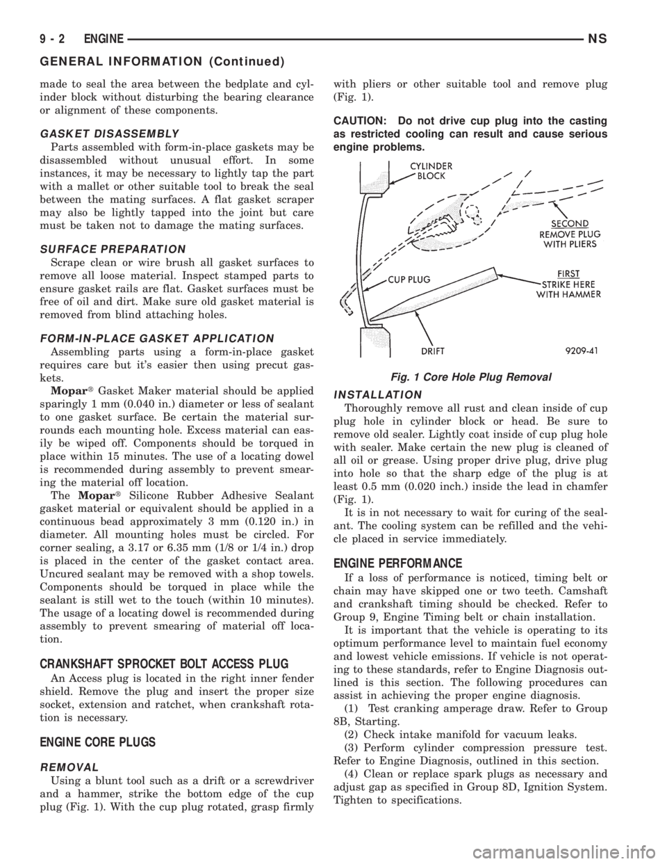
Using a blunt tool such as a drift or a screwdriver
and a hammer, strike the bottom edge of the cup
plug (Fig. 1). With the cup plug rotated, grasp firmlywith pliers or other suitable tool and remove plug
(Fig. 1).
CAUTION: Do not drive cup plug into the casting
as restricted cooling can result and cause serious
engine problems.
INSTALLATION
Thoroughly remove all rust and clean inside of cup
plug hole in cylinder block or head. Be sure to
remove old sealer. Lightly coat inside of cup plug hole
with sealer. Make certain the new plug is cleaned of
all oil or grease. Using proper drive plug, drive plug
into hole so that the sharp edge of the plug is at
least 0.5 mm (0.020 inch.) inside the lead in chamfer
(Fig. 1).
It is in not necessary to wait for curing of the seal-
ant. The cooling system can be refilled and the vehi-
cle placed in service immediately.
ENGINE PERFORMANCE
If a loss of performance is noticed, timing belt or
chain may have skipped one or two teeth. Camshaft
and crankshaft timing should be checked. Refer to
Group 9, Engine Timing belt or chain installation.
It is important that the vehicle is operating to its
optimum performance level to maintain fuel economy
and lowest vehicle emissions. If vehicle is not operat-
ing to these standards, refer to Engine Diagnosis out-
lined is this section. The following procedures can
assist in achieving the proper engine diagnosis.
(1) Test cranking amperage draw. Refer to Group
8B, Starting.
(2) Check intake manifold for vacuum leaks.
(3) Perform cylinder compression pressure test.
Refer to Engine Diagnosis, outlined in this section.
(4) Clean or replace spark plugs as necessary and
adjust gap as specified in Group 8D, Ignition System.
Tighten to specifications.
Fig. 1 Core Hole Plug Removal
9 - 2 ENGINENS
GENERAL INFORMATION (Continued)
Page 1065 of 1938
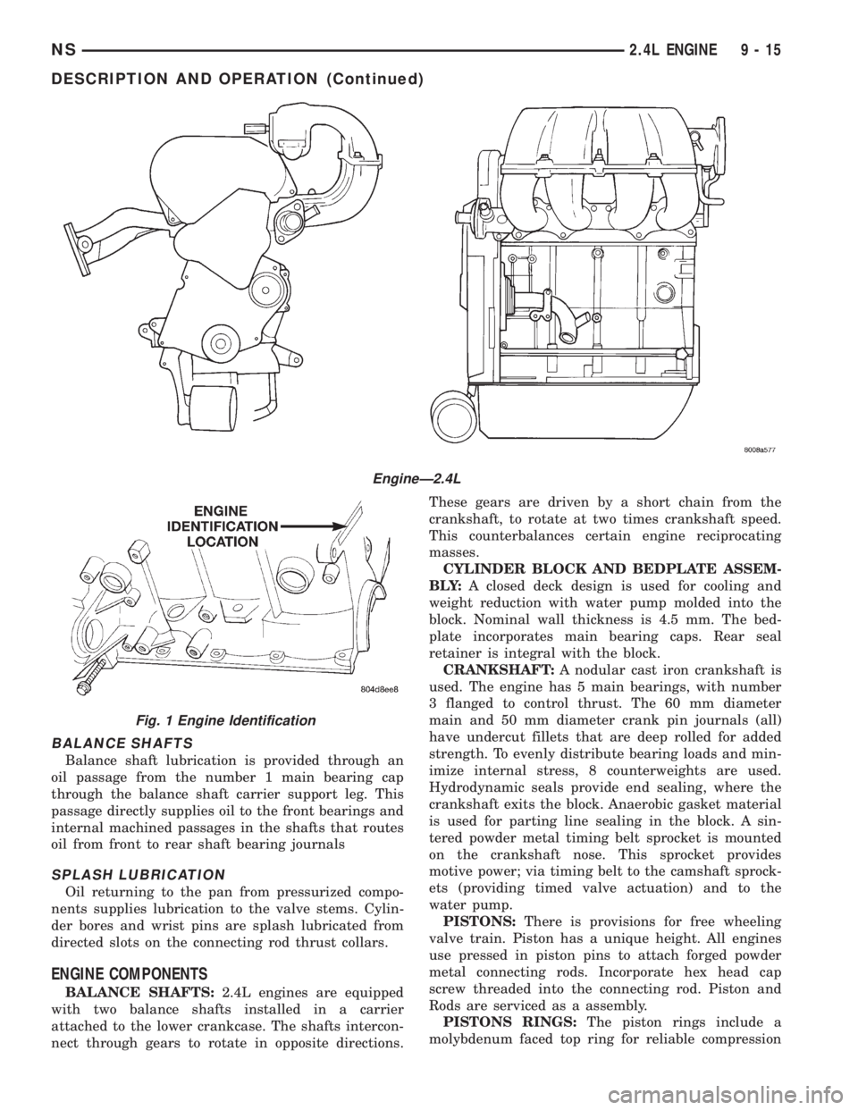
BALANCE SHAFTS
Balance shaft lubrication is provided through an
oil passage from the number 1 main bearing cap
through the balance shaft carrier support leg. This
passage directly supplies oil to the front bearings and
internal machined passages in the shafts that routes
oil from front to rear shaft bearing journals
SPLASH LUBRICATION
Oil returning to the pan from pressurized compo-
nents supplies lubrication to the valve stems. Cylin-
der bores and wrist pins are splash lubricated from
directed slots on the connecting rod thrust collars.
ENGINE COMPONENTS
BALANCE SHAFTS:2.4L engines are equipped
with two balance shafts installed in a carrier
attached to the lower crankcase. The shafts intercon-
nect through gears to rotate in opposite directions.These gears are driven by a short chain from the
crankshaft, to rotate at two times crankshaft speed.
This counterbalances certain engine reciprocating
masses.
CYLINDER BLOCK AND BEDPLATE ASSEM-
B LY:A closed deck design is used for cooling and
weight reduction with water pump molded into the
block. Nominal wall thickness is 4.5 mm. The bed-
plate incorporates main bearing caps. Rear seal
retainer is integral with the block.
CRANKSHAFT:A nodular cast iron crankshaft is
used. The engine has 5 main bearings, with number
3 flanged to control thrust. The 60 mm diameter
main and 50 mm diameter crank pin journals (all)
have undercut fillets that are deep rolled for added
strength. To evenly distribute bearing loads and min-
imize internal stress, 8 counterweights are used.
Hydrodynamic seals provide end sealing, where the
crankshaft exits the block. Anaerobic gasket material
is used for parting line sealing in the block. A sin-
tered powder metal timing belt sprocket is mounted
on the crankshaft nose. This sprocket provides
motive power; via timing belt to the camshaft sprock-
ets (providing timed valve actuation) and to the
water pump.
PISTONS:There is provisions for free wheeling
valve train. Piston has a unique height. All engines
use pressed in piston pins to attach forged powder
metal connecting rods. Incorporate hex head cap
screw threaded into the connecting rod. Piston and
Rods are serviced as a assembly.
PISTONS RINGS:The piston rings include a
molybdenum faced top ring for reliable compression
EngineÐ2.4L
Fig. 1 Engine Identification
NS2.4L ENGINE 9 - 15
DESCRIPTION AND OPERATION (Continued)
Page 1099 of 1938
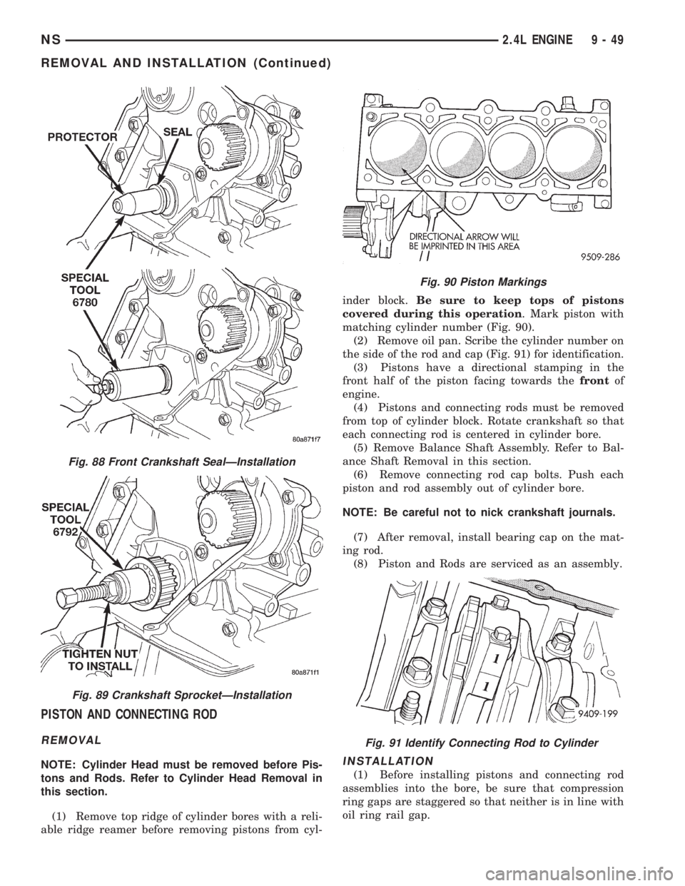
PISTON AND CONNECTING ROD
REMOVAL
NOTE: Cylinder Head must be removed before Pis-
tons and Rods. Refer to Cylinder Head Removal in
this section.
(1) Remove top ridge of cylinder bores with a reli-
able ridge reamer before removing pistons from cyl-inder block.Be sure to keep tops of pistons
covered during this operation. Mark piston with
matching cylinder number (Fig. 90).
(2) Remove oil pan. Scribe the cylinder number on
the side of the rod and cap (Fig. 91) for identification.
(3) Pistons have a directional stamping in the
front half of the piston facing towards thefrontof
engine.
(4) Pistons and connecting rods must be removed
from top of cylinder block. Rotate crankshaft so that
each connecting rod is centered in cylinder bore.
(5) Remove Balance Shaft Assembly. Refer to Bal-
ance Shaft Removal in this section.
(6) Remove connecting rod cap bolts. Push each
piston and rod assembly out of cylinder bore.
NOTE: Be careful not to nick crankshaft journals.
(7) After removal, install bearing cap on the mat-
ing rod.
(8) Piston and Rods are serviced as an assembly.INSTALLATION
(1) Before installing pistons and connecting rod
assemblies into the bore, be sure that compression
ring gaps are staggered so that neither is in line with
oil ring rail gap.
Fig. 88 Front Crankshaft SealÐInstallation
Fig. 89 Crankshaft SprocketÐInstallation
Fig. 90 Piston Markings
Fig. 91 Identify Connecting Rod to Cylinder
NS2.4L ENGINE 9 - 49
REMOVAL AND INSTALLATION (Continued)
Page 1105 of 1938
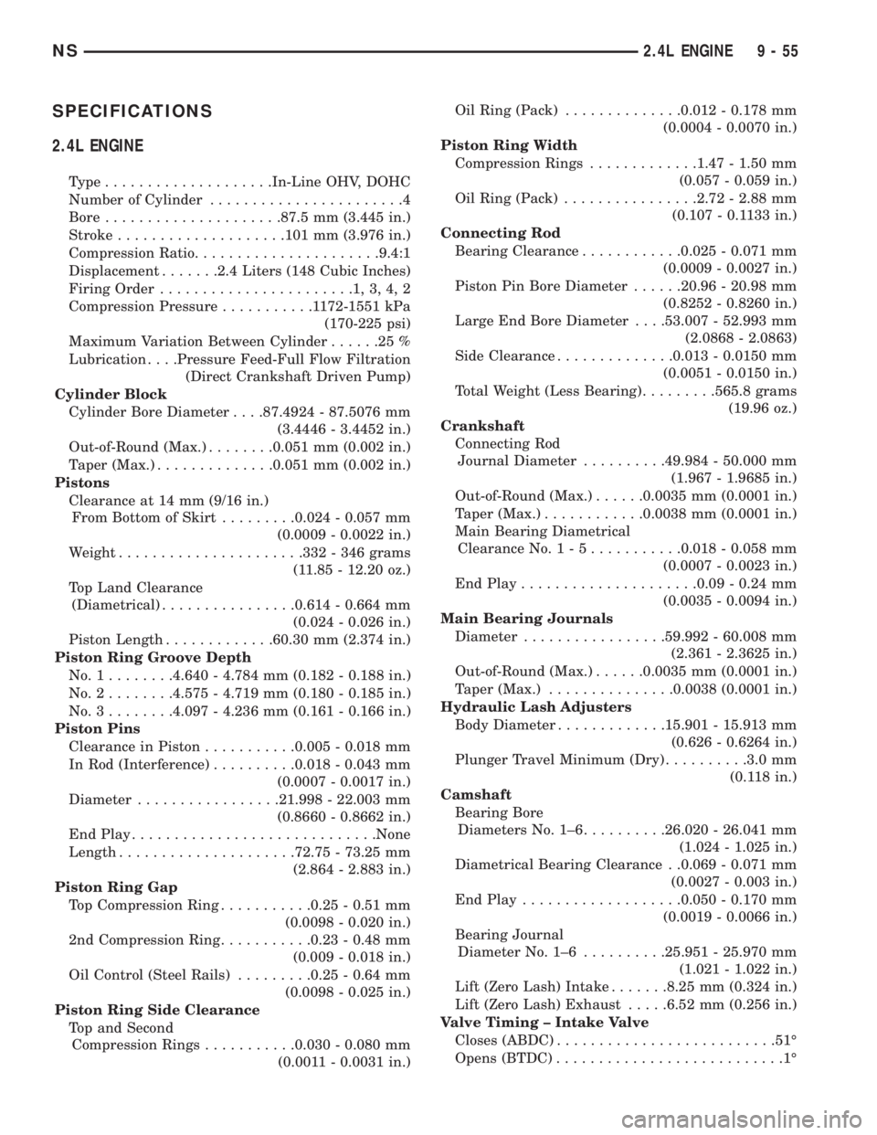
SPECIFICATIONS
2.4L ENGINE
Type....................In-Line OHV, DOHC
Number of Cylinder.......................4
Bore.....................87.5 mm (3.445 in.)
Stroke....................101 mm (3.976 in.)
Compression Ratio......................9.4:1
Displacement.......2.4 Liters (148 Cubic Inches)
Firing Order.......................1,3,4,2
Compression Pressure...........1172-1551 kPa
(170-225 psi)
Maximum Variation Between Cylinder......25%
Lubrication. . . .Pressure Feed-Full Flow Filtration
(Direct Crankshaft Driven Pump)
Cylinder Block
Cylinder Bore Diameter. . . .87.4924 - 87.5076 mm
(3.4446 - 3.4452 in.)
Out-of-Round (Max.)........0.051 mm (0.002 in.)
Taper (Max.)..............0.051 mm (0.002 in.)
Pistons
Clearance at 14 mm (9/16 in.)
From Bottom of Skirt.........0.024 - 0.057 mm
(0.0009 - 0.0022 in.)
Weight......................332 - 346 grams
(11.85 - 12.20 oz.)
Top Land Clearance
(Diametrical)................0.614 - 0.664 mm
(0.024 - 0.026 in.)
Piston Length.............60.30 mm (2.374 in.)
Piston Ring Groove Depth
No.1........4.640 - 4.784 mm (0.182 - 0.188 in.)
No.2........4.575 - 4.719 mm (0.180 - 0.185 in.)
No.3........4.097 - 4.236 mm (0.161 - 0.166 in.)
Piston Pins
Clearance in Piston...........0.005 - 0.018 mm
In Rod (Interference)..........0.018 - 0.043 mm
(0.0007 - 0.0017 in.)
Diameter.................21.998 - 22.003 mm
(0.8660 - 0.8662 in.)
End Play.............................None
Length.....................72.75 - 73.25 mm
(2.864 - 2.883 in.)
Piston Ring Gap
Top Compression Ring...........0.25 - 0.51 mm
(0.0098 - 0.020 in.)
2nd Compression Ring...........0.23 - 0.48 mm
(0.009 - 0.018 in.)
Oil Control (Steel Rails).........0.25 - 0.64 mm
(0.0098 - 0.025 in.)
Piston Ring Side Clearance
Top and Second
Compression Rings...........0.030 - 0.080 mm
(0.0011 - 0.0031 in.)Oil Ring (Pack)..............0.012 - 0.178 mm
(0.0004 - 0.0070 in.)
Piston Ring Width
Compression Rings.............1.47 - 1.50 mm
(0.057 - 0.059 in.)
Oil Ring (Pack)................2.72 - 2.88 mm
(0.107 - 0.1133 in.)
Connecting Rod
Bearing Clearance............0.025 - 0.071 mm
(0.0009 - 0.0027 in.)
Piston Pin Bore Diameter......20.96 - 20.98 mm
(0.8252 - 0.8260 in.)
Large End Bore Diameter. . . .53.007 - 52.993 mm
(2.0868 - 2.0863)
Side Clearance..............0.013 - 0.0150 mm
(0.0051 - 0.0150 in.)
Total Weight (Less Bearing).........565.8 grams
(19.96 oz.)
Crankshaft
Connecting Rod
Journal Diameter..........49.984 - 50.000 mm
(1.967 - 1.9685 in.)
Out-of-Round (Max.)......0.0035 mm (0.0001 in.)
Taper (Max.)............0.0038 mm (0.0001 in.)
Main Bearing Diametrical
Clearance No.1-5...........0.018 - 0.058 mm
(0.0007 - 0.0023 in.)
End Play.....................0.09 - 0.24 mm
(0.0035 - 0.0094 in.)
Main Bearing Journals
Diameter.................59.992 - 60.008 mm
(2.361 - 2.3625 in.)
Out-of-Round (Max.)......0.0035 mm (0.0001 in.)
Taper (Max.)...............0.0038 (0.0001 in.)
Hydraulic Lash Adjusters
Body Diameter.............15.901 - 15.913 mm
(0.626 - 0.6264 in.)
Plunger Travel Minimum (Dry)..........3.0 mm
(0.118 in.)
Camshaft
Bearing Bore
Diameters No. 1±6..........26.020 - 26.041 mm
(1.024 - 1.025 in.)
Diametrical Bearing Clearance . .0.069 - 0.071 mm
(0.0027 - 0.003 in.)
End Play...................0.050 - 0.170 mm
(0.0019 - 0.0066 in.)
Bearing Journal
Diameter No. 1±6..........25.951 - 25.970 mm
(1.021 - 1.022 in.)
Lift (Zero Lash) Intake.......8.25 mm (0.324 in.)
Lift (Zero Lash) Exhaust.....6.52 mm (0.256 in.)
Valve Timing ± Intake Valve
Closes (ABDC)..........................51É
Opens (BTDC)...........................1É
NS2.4L ENGINE 9 - 55
Page 1139 of 1938
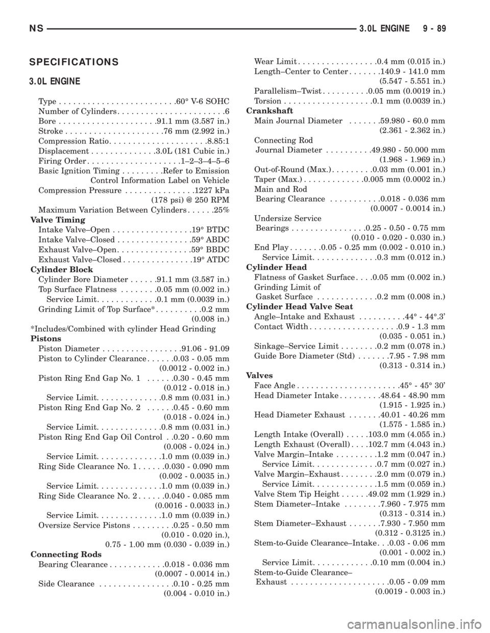
SPECIFICATIONS
3.0L ENGINE
Type.........................60É V-6 SOHC
Number of Cylinders.......................6
Bore.....................91.1 mm (3.587 in.)
Stroke.....................76mm(2.992 in.)
Compression Ratio.....................8.85:1
Displacement..............3.0L (181 Cubic in.)
Firing Order....................1±2±3±4±5±6
Basic Ignition Timing.........Refer to Emission
Control Information Label on Vehicle
Compression Pressure...............1227 kPa
(178 psi) @ 250 RPM
Maximum Variation Between Cylinders......25%
Valve Timing
Intake Valve±Open.................19É BTDC
Intake Valve±Closed................59É ABDC
Exhaust Valve±Open................59É BBDC
Exhaust Valve±Closed...............19É ATDC
Cylinder Block
Cylinder Bore Diameter......91.1 mm (3.587 in.)
Top Surface Flatness........0.05 mm (0.002 in.)
Service Limit.............0.1 mm (0.0039 in.)
Grinding Limit of Top Surface*..........0.2 mm
(0.008 in.)
*Includes/Combined with cylinder Head Grinding
Pistons
Piston Diameter.................91.06 - 91.09
Piston to Cylinder Clearance......0.03 - 0.05 mm
(0.0012 - 0.002 in.)
Piston Ring End Gap No. 1......0.30 - 0.45 mm
(0.012 - 0.018 in.)
Service Limit..............0.8 mm (0.031 in.)
Piston Ring End Gap No. 2......0.45 - 0.60 mm
(0.018 - 0.024 in.)
Service Limit..............0.8 mm (0.031 in.)
Piston Ring End Gap Oil Control . .0.20 - 0.60 mm
(0.008 - 0.024 in.)
Service Limit..............1.0 mm (0.039 in.)
Ring Side Clearance No. 1......0.030 - 0.090 mm
(0.002 - 0.0035 in.)
Service Limit..............1.0 mm (0.039 in.)
Ring Side Clearance No. 2......0.040 - 0.085 mm
(0.0016 - 0.0033 in.)
Service Limit..............1.0 mm (0.039 in.)
Oversize Service Pistons.........0.25 - 0.50 mm
(0.010 - 0.020 in.),
0.75 - 1.00 mm (0.030 - 0.039 in.)
Connecting Rods
Bearing Clearance............0.018 - 0.036 mm
(0.0007 - 0.0014 in.)
Side Clearance................0.10 - 0.25 mm
(0.004 - 0.010 in.)Wear Limit.................0.4 mm (0.015 in.)
Length±Center to Center.......140.9 - 141.0 mm
(5.547 - 5.551 in.)
Parallelism±Twist..........0.05 mm (0.0019 in.)
Torsion...................0.1 mm (0.0039 in.)
Crankshaft
Main Journal Diameter.......59.980 - 60.0 mm
(2.361 - 2.362 in.)
Connecting Rod
Journal Diameter..........49.980 - 50.000 mm
(1.968 - 1.969 in.)
Out-of-Round (Max.).........0.03 mm (0.001 in.)
Taper (Max.).............0.005 mm (0.0002 in.)
Main and Rod
Bearing Clearance...........0.018 - 0.036 mm
(0.0007 - 0.0014 in.)
Undersize Service
Bearings................0.25 - 0.50 - 0.75 mm
(0.010 - 0.020 - 0.030 in.)
End Play.......0.05 - 0.25 mm (0.002 - 0.010 in.)
Service Limit..............0.3 mm (0.012 in.)
Cylinder Head
Flatness of Gasket Surface. . . .0.05 mm (0.002 in.)
Grinding Limit of
Gasket Surface.............0.2 mm (0.008 in.)
Cylinder Head Valve Seat
Angle±Intake and Exhaust..........44É - 44É.3'
Contact Width...................0.9 - 1.3 mm
(0.035 - 0.051 in.)
Sinkage±Service Limit........0.2 mm (0.078 in.)
Guide Bore Diameter (Std).......7.95 - 7.98 mm
(0.313 - 0.314 in.)
Valves
Face Angle......................45É - 45É 30'
Head Diameter Intake.........48.64 - 48.90 mm
(1.915 - 1.925 in.)
Head Diameter Exhaust.......40.01 - 40.26 mm
(1.575 - 1.585 in.)
Length Intake (Overall).....103.0 mm (4.055 in.)
Length Exhaust (Overall). . . .102.7 mm (4.043 in.)
Valve Margin±Intake.........1.2 mm (0.047 in.)
Service Limit..............0.7 mm (0.027 in.)
Valve Margin±Exhaust........2.0 mm (0.079 in.)
Service Limit..............1.5 mm (0.059 in.)
Valve Stem Tip Height......49.02 mm (1.929 in.)
Stem Diameter±Intake........7.960 - 7.975 mm
(0.313 - 0.314 in.)
Stem Diameter±Exhaust.......7.930 - 7.950 mm
(0.312 - 0.3125 in.)
Stem-to-Guide Clearance±Intake . . .0.03 - 0.06 mm
(0.001 - 0.002 in.)
Service Limit.............0.10 mm (0.004 in.)
Stem-to-Guide Clearance±
Exhaust.....................0.05 - 0.09 mm
(0.0019 - 0.003 in.)
NS3.0L ENGINE 9 - 89
Page 1143 of 1938
3.3/3.8L ENGINE
INDEX
page page
DESCRIPTION AND OPERATION
ENGINE COMPONENTS.................. 93
ENGINE IDENTIFICATION................. 93
ENGINE LUBRICATION SYSTEM............ 93
DIAGNOSIS AND TESTING
CHECKING ENGINE OIL PRESSURE......... 96
HYDRAULIC TAPPETS.................... 94
SERVICE PROCEDURES
CRANKSHAFT END PLAY................. 99
FITTING CONNECTING ROD BEARINGS...... 97
FITTING MAIN BEARINGS................. 98
FITTING PISTONS AND RINGS............. 97
MEASURING TIMING CHAIN FOR STRETCH . . . 96
VALVE SERVICE RECONDITION........... 100
VALVE TIMING.......................... 96
REMOVAL AND INSTALLATION
CAMSHAFT BEARINGS.................. 114
CAMSHAFT........................... 113
CRANKSHAFT DAMPER................. 106
CRANKSHAFT OIL SEALÐFRONT.......... 117
CRANKSHAFT OIL SEALÐREAR........... 118
CRANKSHAFT......................... 116
CYLINDER HEAD COVER................ 107
CYLINDER HEAD....................... 108
ENGINE ASSEMBLY..................... 104
ENGINE MOUNTS...................... 102
ENGINE OIL GALLERY PLUGS............. 119OILFILTER ............................ 119
OILPAN .............................. 114
PISTON AND CONNECTING ROD.......... 115
ROCKER ARMS AND SHAFT ASSEMBLY..... 106
TAPPET REMOVAL...................... 110
TIMING CHAIN COVER................... 111
TIMING CHAIN......................... 112
VALVE STEM SEALS OR SPRINGS,
CYLINDER HEAD NOT REMOVED........ 106
VALVES AND VALVE SPRINGS............ 109
WIPER UNIT.......................... 102
DISASSEMBLY AND ASSEMBLY
HYDRAULIC TAPPETS................... 120
OIL PUMP............................ 119
CLEANING AND INSPECTION
CYLINDER HEAD....................... 120
ENGINE BLOCK AND BORE............... 121
OILPAN .............................. 121
OIL PUMP............................ 121
ADJUSTMENTS
ENGINE MOUNTS...................... 123
SPECIFICATIONS
3.3/3.8L ENGINE....................... 123
TORQUE CHART....................... 125
SPECIAL TOOLS
3.3/3.8L ENGINE....................... 127
DESCRIPTION AND OPERATION
ENGINE IDENTIFICATION
The engine identification number is located on the
rear of the cylinder block just below the cylinder
head (Fig. 1).
ENGINE LUBRICATION SYSTEM
The lubrication system is a full flow filtration pres-
sure feed type. Oil from the oil pan is pumped by a
internal gear type oil pump directly coupled to the
crankshaft. The pressure is regulated by a relief
valve located in the chain case cover. The oil is
pumped through an oil filter and feeds a main oil
galley. This oil gallery feeds oil under pressure to the
main and rod bearings, camshaft bearings. Passages
in the cylinder block feed oil to the hydraulic lifters
and rocker shaft brackets which feeds the rocker arm
pivots (Fig. 2).
ENGINE COMPONENTS
ENGINE:The 3.3L (201 Cubic Inches) and 3.8L
(231 Cubic Inches) displacement engines are 60É V
type six cylinder power plants with cast iron cylinder
blocks and aluminum cylinder heads (Fig. 3). Firing
order for these engines is 1-2-3-4-5-6. High turbu-
lence cylinder heads allow a 8.9-1 compression ratio.
CRANKSHAFT:The nodular iron crankshaft is
supported by four main bearings, with number two
being the thrust bearing. Crankshaft end sealing is
provided by front and rear rubber seals.
PISTONS:The pistons are cast aluminum alloy.
Three rings are used. Piston pins, press fitted into
place, join the pistons to forged steel connecting rods.
CAMSHAFT:The nodular iron camshaft is
mounted in four steel backed babbitt bearings. A
thrust plate located in front of the first bearing, and
bolted to the block, controls end play. Silent timing
chain drives the camshaft. This chain is enclosed by
a cast aluminum cover which also carries a front
NS3.3/3.8L ENGINE 9 - 93
Page 1152 of 1938
NOTE: Valve seats which are worn or burned can
be reworked, provided that correct angle and seat
width are maintained. Otherwise cylinder head must
be replaced.
(4) When seat is properly positioned the width of
intake seats should be 1.75 to 2.25 mm (0.69 to 0.088
in.) The width of the exhaust seats should be 1.50 to
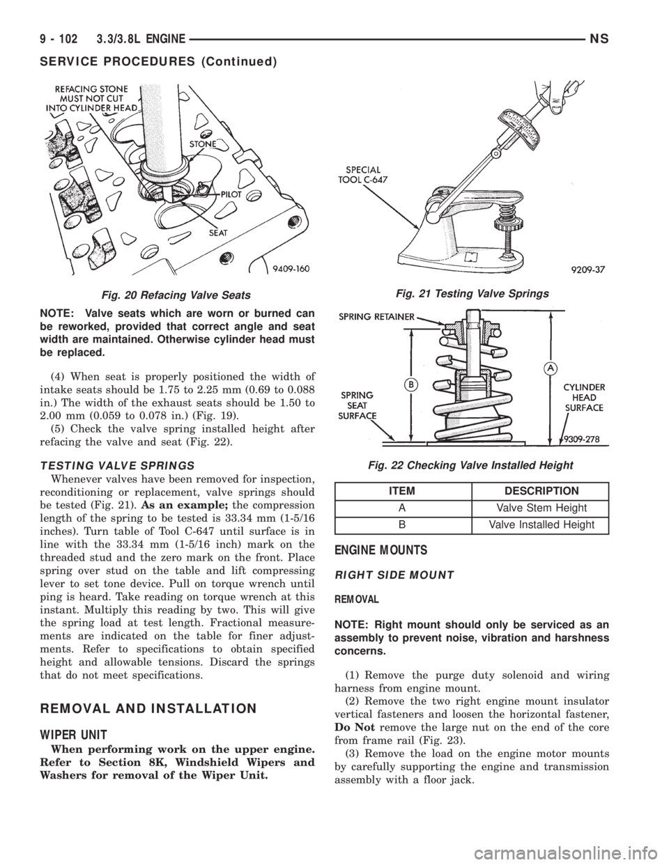
2.00 mm (0.059 to 0.078 in.) (Fig. 19).
(5) Check the valve spring installed height after
refacing the valve and seat (Fig. 22).
TESTING VALVE SPRINGS
Whenever valves have been removed for inspection,
reconditioning or replacement, valve springs should
be tested (Fig. 21).As an example;the compression
length of the spring to be tested is 33.34 mm (1-5/16
inches). Turn table of Tool C-647 until surface is in
line with the 33.34 mm (1-5/16 inch) mark on the
threaded stud and the zero mark on the front. Place
spring over stud on the table and lift compressing
lever to set tone device. Pull on torque wrench until
ping is heard. Take reading on torque wrench at this
instant. Multiply this reading by two. This will give
the spring load at test length. Fractional measure-
ments are indicated on the table for finer adjust-
ments. Refer to specifications to obtain specified
height and allowable tensions. Discard the springs
that do not meet specifications.
REMOVAL AND INSTALLATION
WIPER UNIT
When performing work on the upper engine.
Refer to Section 8K, Windshield Wipers and
Washers for removal of the Wiper Unit.
ENGINE MOUNTS
RIGHT SIDE MOUNT
REMOVAL
NOTE: Right mount should only be serviced as an
assembly to prevent noise, vibration and harshness
concerns.
(1) Remove the purge duty solenoid and wiring
harness from engine mount.
(2) Remove the two right engine mount insulator
vertical fasteners and loosen the horizontal fastener,
Do Notremove the large nut on the end of the core
from frame rail (Fig. 23).
(3) Remove the load on the engine motor mounts
by carefully supporting the engine and transmission
assembly with a floor jack.
Fig. 20 Refacing Valve SeatsFig. 21 Testing Valve Springs
Fig. 22 Checking Valve Installed Height
ITEM DESCRIPTION
A Valve Stem Height
B Valve Installed Height
9 - 102 3.3/3.8L ENGINENS
SERVICE PROCEDURES (Continued)