check engine CHRYSLER VOYAGER 1996 Service Manual
[x] Cancel search | Manufacturer: CHRYSLER, Model Year: 1996, Model line: VOYAGER, Model: CHRYSLER VOYAGER 1996Pages: 1938, PDF Size: 55.84 MB
Page 1149 of 1938
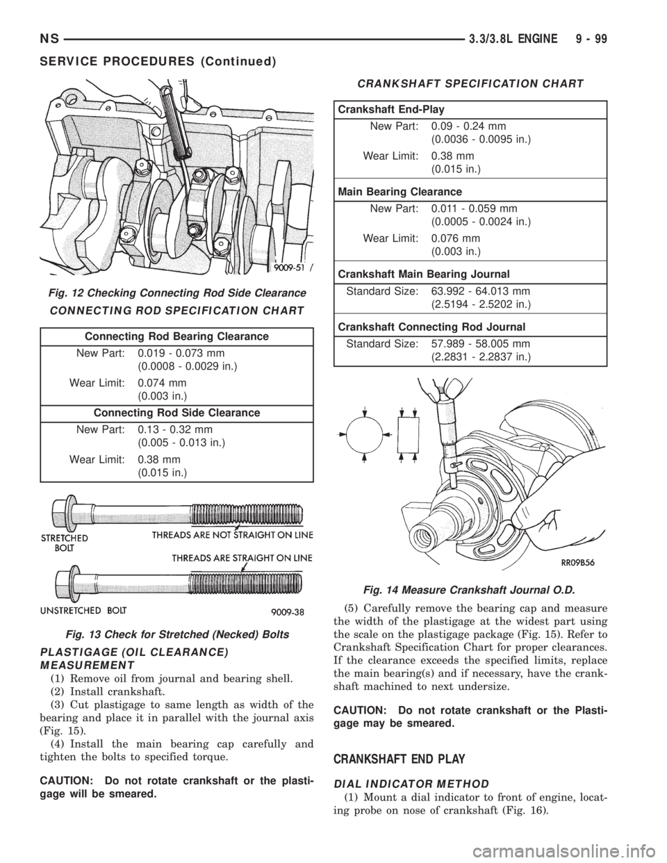
PLASTIGAGE (OIL CLEARANCE)
MEASUREMENT
(1) Remove oil from journal and bearing shell.
(2) Install crankshaft.
(3) Cut plastigage to same length as width of the
bearing and place it in parallel with the journal axis
(Fig. 15).
(4) Install the main bearing cap carefully and
tighten the bolts to specified torque.
CAUTION: Do not rotate crankshaft or the plasti-
gage will be smeared.(5) Carefully remove the bearing cap and measure
the width of the plastigage at the widest part using
the scale on the plastigage package (Fig. 15). Refer to
Crankshaft Specification Chart for proper clearances.
If the clearance exceeds the specified limits, replace
the main bearing(s) and if necessary, have the crank-
shaft machined to next undersize.
CAUTION: Do not rotate crankshaft or the Plasti-
gage may be smeared.
CRANKSHAFT END PLAY
DIAL INDICATOR METHOD
(1) Mount a dial indicator to front of engine, locat-
ing probe on nose of crankshaft (Fig. 16).
Fig. 12 Checking Connecting Rod Side Clearance
CONNECTING ROD SPECIFICATION CHART
Connecting Rod Bearing Clearance
New Part: 0.019 - 0.073 mm
(0.0008 - 0.0029 in.)
Wear Limit: 0.074 mm
(0.003 in.)
Connecting Rod Side Clearance
New Part: 0.13 - 0.32 mm
(0.005 - 0.013 in.)
Wear Limit: 0.38 mm
(0.015 in.)
Fig. 13 Check for Stretched (Necked) Bolts
CRANKSHAFT SPECIFICATION CHART
Crankshaft End-Play
New Part: 0.09 - 0.24 mm
(0.0036 - 0.0095 in.)
Wear Limit: 0.38 mm
(0.015 in.)
Main Bearing Clearance
New Part: 0.011 - 0.059 mm
(0.0005 - 0.0024 in.)
Wear Limit: 0.076 mm
(0.003 in.)
Crankshaft Main Bearing Journal
Standard Size: 63.992 - 64.013 mm
(2.5194 - 2.5202 in.)
Crankshaft Connecting Rod Journal
Standard Size: 57.989 - 58.005 mm
(2.2831 - 2.2837 in.)
Fig. 14 Measure Crankshaft Journal O.D.
NS3.3/3.8L ENGINE 9 - 99
SERVICE PROCEDURES (Continued)
Page 1150 of 1938
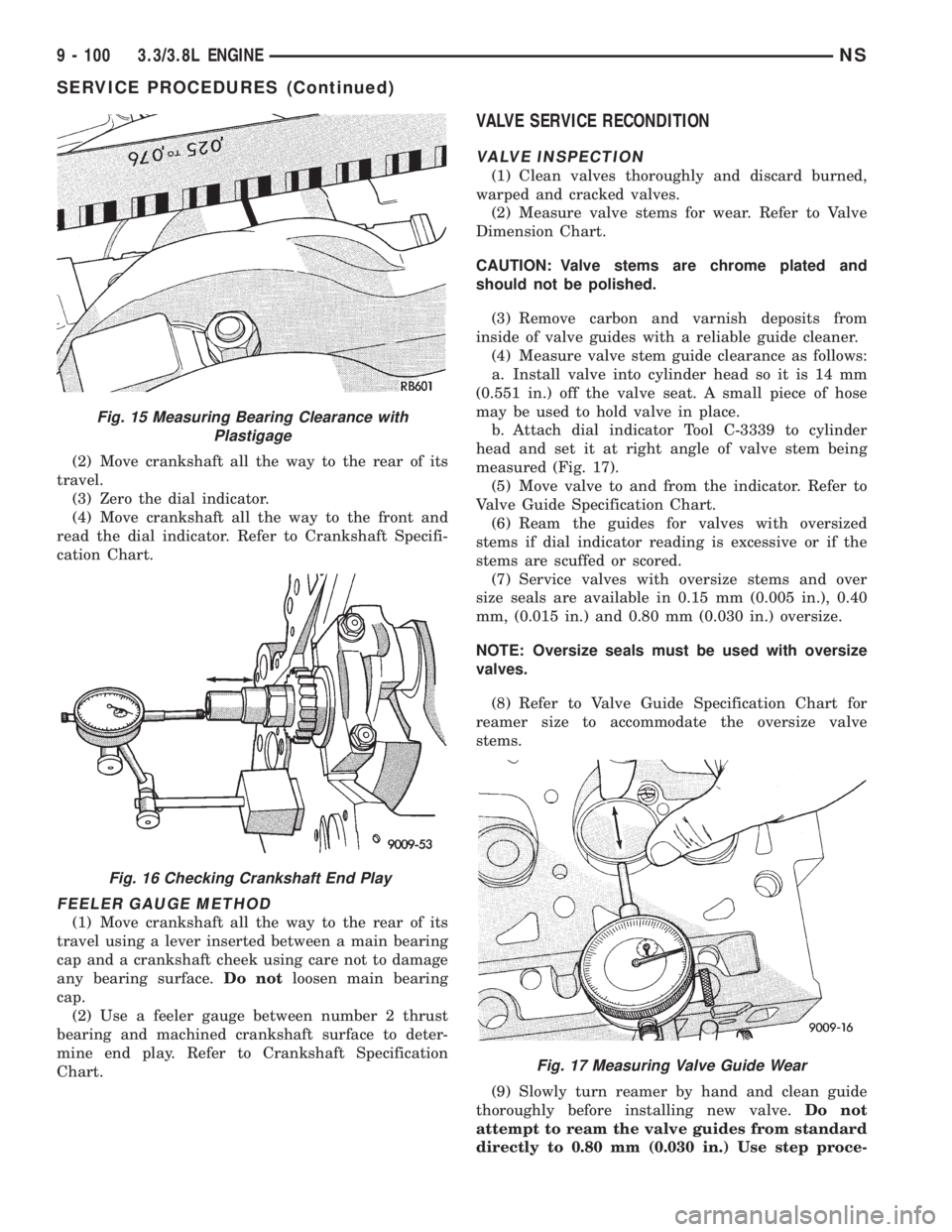
(2) Move crankshaft all the way to the rear of its
travel.
(3) Zero the dial indicator.
(4) Move crankshaft all the way to the front and
read the dial indicator. Refer to Crankshaft Specifi-
cation Chart.
FEELER GAUGE METHOD
(1) Move crankshaft all the way to the rear of its
travel using a lever inserted between a main bearing
cap and a crankshaft cheek using care not to damage
any bearing surface.Do notloosen main bearing
cap.
(2) Use a feeler gauge between number 2 thrust
bearing and machined crankshaft surface to deter-
mine end play. Refer to Crankshaft Specification
Chart.
VALVE SERVICE RECONDITION
VALVE INSPECTION
(1) Clean valves thoroughly and discard burned,
warped and cracked valves.
(2) Measure valve stems for wear. Refer to Valve
Dimension Chart.
CAUTION: Valve stems are chrome plated and
should not be polished.
(3) Remove carbon and varnish deposits from
inside of valve guides with a reliable guide cleaner.
(4) Measure valve stem guide clearance as follows:
a. Install valve into cylinder head so it is 14 mm
(0.551 in.) off the valve seat. A small piece of hose
may be used to hold valve in place.
b. Attach dial indicator Tool C-3339 to cylinder
head and set it at right angle of valve stem being
measured (Fig. 17).
(5) Move valve to and from the indicator. Refer to
Valve Guide Specification Chart.
(6) Ream the guides for valves with oversized
stems if dial indicator reading is excessive or if the
stems are scuffed or scored.
(7) Service valves with oversize stems and over
size seals are available in 0.15 mm (0.005 in.), 0.40
mm, (0.015 in.) and 0.80 mm (0.030 in.) oversize.
NOTE: Oversize seals must be used with oversize
valves.
(8) Refer to Valve Guide Specification Chart for
reamer size to accommodate the oversize valve
stems.
(9) Slowly turn reamer by hand and clean guide
thoroughly before installing new valve.Do not
attempt to ream the valve guides from standard
directly to 0.80 mm (0.030 in.) Use step proce-
Fig. 15 Measuring Bearing Clearance with
Plastigage
Fig. 16 Checking Crankshaft End Play
Fig. 17 Measuring Valve Guide Wear
9 - 100 3.3/3.8L ENGINENS
SERVICE PROCEDURES (Continued)
Page 1152 of 1938
NOTE: Valve seats which are worn or burned can
be reworked, provided that correct angle and seat
width are maintained. Otherwise cylinder head must
be replaced.
(4) When seat is properly positioned the width of
intake seats should be 1.75 to 2.25 mm (0.69 to 0.088
in.) The width of the exhaust seats should be 1.50 to
2.00 mm (0.059 to 0.078 in.) (Fig. 19).
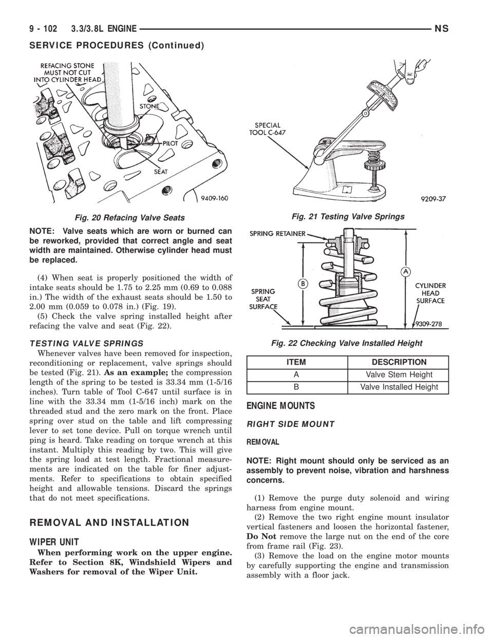
(5) Check the valve spring installed height after
refacing the valve and seat (Fig. 22).
TESTING VALVE SPRINGS
Whenever valves have been removed for inspection,
reconditioning or replacement, valve springs should
be tested (Fig. 21).As an example;the compression
length of the spring to be tested is 33.34 mm (1-5/16
inches). Turn table of Tool C-647 until surface is in
line with the 33.34 mm (1-5/16 inch) mark on the
threaded stud and the zero mark on the front. Place
spring over stud on the table and lift compressing
lever to set tone device. Pull on torque wrench until
ping is heard. Take reading on torque wrench at this
instant. Multiply this reading by two. This will give
the spring load at test length. Fractional measure-
ments are indicated on the table for finer adjust-
ments. Refer to specifications to obtain specified
height and allowable tensions. Discard the springs
that do not meet specifications.
REMOVAL AND INSTALLATION
WIPER UNIT
When performing work on the upper engine.
Refer to Section 8K, Windshield Wipers and
Washers for removal of the Wiper Unit.
ENGINE MOUNTS
RIGHT SIDE MOUNT
REMOVAL
NOTE: Right mount should only be serviced as an
assembly to prevent noise, vibration and harshness
concerns.
(1) Remove the purge duty solenoid and wiring
harness from engine mount.
(2) Remove the two right engine mount insulator
vertical fasteners and loosen the horizontal fastener,
Do Notremove the large nut on the end of the core
from frame rail (Fig. 23).
(3) Remove the load on the engine motor mounts
by carefully supporting the engine and transmission
assembly with a floor jack.
Fig. 20 Refacing Valve SeatsFig. 21 Testing Valve Springs
Fig. 22 Checking Valve Installed Height
ITEM DESCRIPTION
A Valve Stem Height
B Valve Installed Height
9 - 102 3.3/3.8L ENGINENS
SERVICE PROCEDURES (Continued)
Page 1154 of 1938
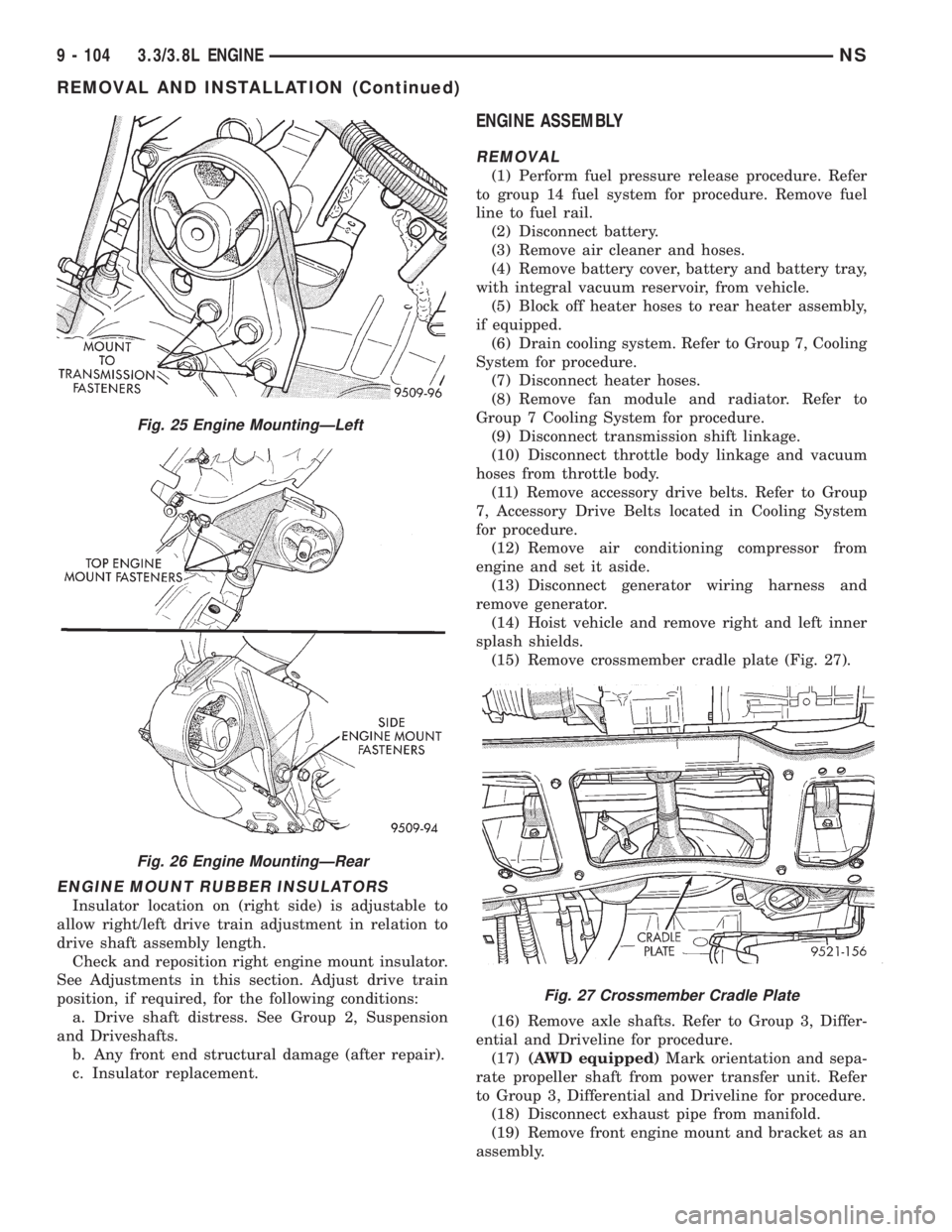
ENGINE MOUNT RUBBER INSULATORS
Insulator location on (right side) is adjustable to
allow right/left drive train adjustment in relation to
drive shaft assembly length.
Check and reposition right engine mount insulator.
See Adjustments in this section. Adjust drive train
position, if required, for the following conditions:
a. Drive shaft distress. See Group 2, Suspension
and Driveshafts.
b. Any front end structural damage (after repair).
c. Insulator replacement.
ENGINE ASSEMBLY
REMOVAL
(1) Perform fuel pressure release procedure. Refer
to group 14 fuel system for procedure. Remove fuel
line to fuel rail.
(2) Disconnect battery.
(3) Remove air cleaner and hoses.
(4) Remove battery cover, battery and battery tray,
with integral vacuum reservoir, from vehicle.
(5) Block off heater hoses to rear heater assembly,
if equipped.
(6) Drain cooling system. Refer to Group 7, Cooling
System for procedure.
(7) Disconnect heater hoses.
(8) Remove fan module and radiator. Refer to
Group 7 Cooling System for procedure.
(9) Disconnect transmission shift linkage.
(10) Disconnect throttle body linkage and vacuum
hoses from throttle body.
(11) Remove accessory drive belts. Refer to Group
7, Accessory Drive Belts located in Cooling System
for procedure.
(12) Remove air conditioning compressor from
engine and set it aside.
(13) Disconnect generator wiring harness and
remove generator.
(14) Hoist vehicle and remove right and left inner
splash shields.
(15) Remove crossmember cradle plate (Fig. 27).
(16) Remove axle shafts. Refer to Group 3, Differ-
ential and Driveline for procedure.
(17)(AWD equipped)Mark orientation and sepa-
rate propeller shaft from power transfer unit. Refer
to Group 3, Differential and Driveline for procedure.
(18) Disconnect exhaust pipe from manifold.
(19) Remove front engine mount and bracket as an
assembly.
Fig. 25 Engine MountingÐLeft
Fig. 26 Engine MountingÐRear
Fig. 27 Crossmember Cradle Plate
9 - 104 3.3/3.8L ENGINENS
REMOVAL AND INSTALLATION (Continued)
Page 1158 of 1938
²Non±isolatedcylinder head cover to 12 N´m
(105 in. lbs.).
²Isolatedcylinder head cover to 10 N´m (90 in.
lbs.) (Fig. 32).
(4) Connect PCV hose from cylinder head cover.
(5) Install intake manifold upper plenum. Refer to
Group 11, Exhaust System and Intake Manifold for
procedure.
(6) Install Wiper Unit. Refer to Group 8K, Wind-
shield Wipers and Washers for procedure.
(7) Connect negative cable to battery.
CYLINDER HEAD
REMOVAL
(1) Drain cooling system. Refer to Group 7, Cooling
System for procedure and disconnect negative cable
from battery.
(2) Remove upper and lower intake manifolds.
Refer to Group 11, Exhaust System and Intake Man-
ifold.
WARNING: INTAKE MANIFOLD GASKET IS MADE
OF VERY THIN METAL AND MAY CAUSE PER-
SONAL INJURY, HANDLE WITH CARE.
(3) Disconnect coil wires, sending unit wire, heater
hoses and bypass hose.
(4) Remove PCV system hoses, evaporation control
system hose and cylinder head covers.
(5) Remove exhaust manifolds.
(6) Remove rocker arm and shaft assemblies.
Remove push rods andmark positions to ensure
installation in original locations.
(7) Remove the 9 head bolts from each cylinder
head and remove cylinder heads (Fig. 33).
INSTALLATION
(1) Clean all sealing surfaces of cylinder block and
cylinder heads.
(2) Install new gaskets on cylinder block (Fig. 34).
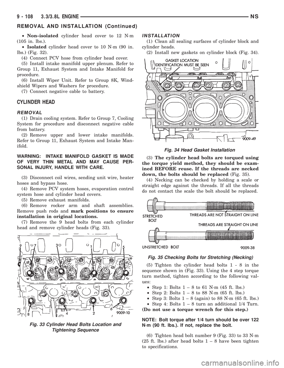
(3)The cylinder head bolts are torqued using
the torque yield method, they should be exam-
ined BEFORE reuse. If the threads are necked
down, the bolts should be replaced(Fig. 35).
(4) Necking can be checked by holding a scale or
straight edge against the threads. If all the threads
do not contact the scale the bolt should be replaced.
(5) Tighten the cylinder head bolts1-8inthe
sequence shown in (Fig. 33). Using the 4 step torque
turn method, tighten according to the following val-
ues:
²Step 1: Bolts1±8to61N´m(45ft.lbs.)
²Step 2: Bolts1±8to88N´m(65ft.lbs.)
²Step 3: Bolts1±8(again) to 88 N´m (65 ft. lbs.)
²Step 4: Bolts1±8turn an additional 1/4 Turn.
(Do not use a torque wrench for this step.)
NOTE: Bolt torque after 1/4 turn should be over 122
N´m (90 ft. lbs.). If not, replace the bolt.
(6) Tighten head bolt number 9 (Fig. 33) to 33 N´m
(25 ft. lbs.) after head bolts1±8have been tighten
to specifications.
Fig. 33 Cylinder Head Bolts Location and
Tightening Sequence
Fig. 34 Head Gasket Installation
Fig. 35 Checking Bolts for Stretching (Necking)
9 - 108 3.3/3.8L ENGINENS
REMOVAL AND INSTALLATION (Continued)
Page 1160 of 1938
(3) Before removing valves,remove any burrs
from valve stem lock grooves to prevent dam-
age to the valve guides.Identify valves to insure
installation in original location.
VALVE INSTALLATION
(1) Coat valve stems with clean engine oil and
insert them in cylinder head.
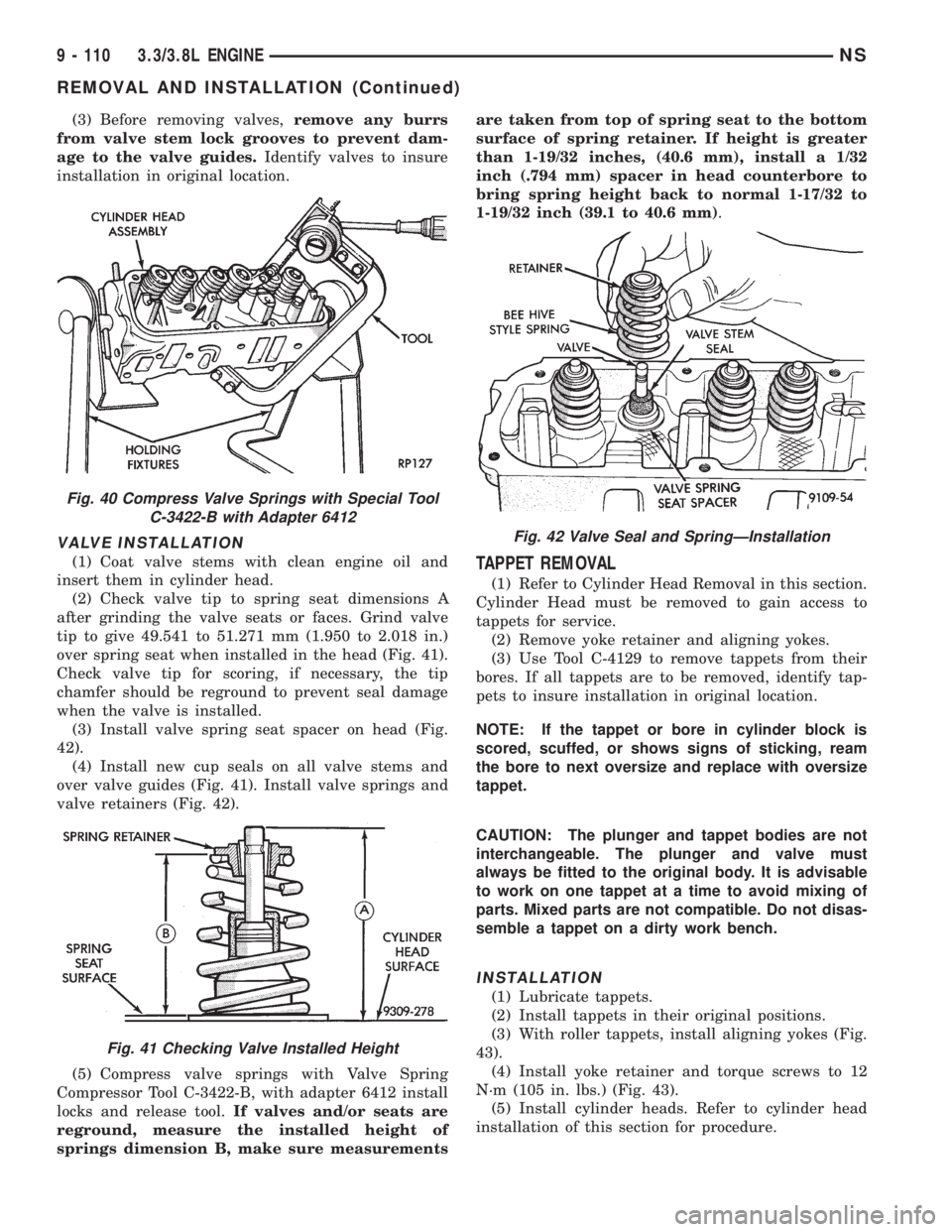
(2) Check valve tip to spring seat dimensions A
after grinding the valve seats or faces. Grind valve
tip to give 49.541 to 51.271 mm (1.950 to 2.018 in.)
over spring seat when installed in the head (Fig. 41).
Check valve tip for scoring, if necessary, the tip
chamfer should be reground to prevent seal damage
when the valve is installed.
(3) Install valve spring seat spacer on head (Fig.
42).
(4) Install new cup seals on all valve stems and
over valve guides (Fig. 41). Install valve springs and
valve retainers (Fig. 42).
(5) Compress valve springs with Valve Spring
Compressor Tool C-3422-B, with adapter 6412 install
locks and release tool.If valves and/or seats are
reground, measure the installed height of
springs dimension B, make sure measurementsare taken from top of spring seat to the bottom
surface of spring retainer. If height is greater
than 1-19/32 inches, (40.6 mm), install a 1/32
inch (.794 mm) spacer in head counterbore to
bring spring height back to normal 1-17/32 to
1-19/32 inch (39.1 to 40.6 mm).TAPPET REMOVAL
(1) Refer to Cylinder Head Removal in this section.
Cylinder Head must be removed to gain access to
tappets for service.
(2) Remove yoke retainer and aligning yokes.
(3) Use Tool C-4129 to remove tappets from their
bores. If all tappets are to be removed, identify tap-
pets to insure installation in original location.
NOTE: If the tappet or bore in cylinder block is
scored, scuffed, or shows signs of sticking, ream
the bore to next oversize and replace with oversize
tappet.
CAUTION: The plunger and tappet bodies are not
interchangeable. The plunger and valve must
always be fitted to the original body. It is advisable
to work on one tappet at a time to avoid mixing of
parts. Mixed parts are not compatible. Do not disas-
semble a tappet on a dirty work bench.
INSTALLATION
(1) Lubricate tappets.
(2) Install tappets in their original positions.
(3) With roller tappets, install aligning yokes (Fig.
43).
(4) Install yoke retainer and torque screws to 12
N´m (105 in. lbs.) (Fig. 43).
(5) Install cylinder heads. Refer to cylinder head
installation of this section for procedure.
Fig. 40 Compress Valve Springs with Special Tool
C-3422-B with Adapter 6412
Fig. 41 Checking Valve Installed Height
Fig. 42 Valve Seal and SpringÐInstallation
9 - 110 3.3/3.8L ENGINENS
REMOVAL AND INSTALLATION (Continued)
Page 1163 of 1938
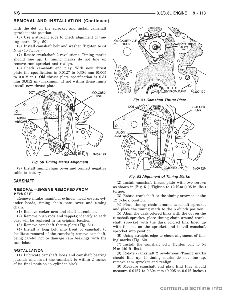
with the dot on the sprocket and install camshaft
sprocket into position.
(5) Use a straight edge to check alignment of tim-
ing marks (Fig. 50).
(6) Install camshaft bolt and washer. Tighten to 54
N´m (40 ft. lbs.).
(7) Rotate crankshaft 2 revolutions. Timing marks
should line up. If timing marks do not line up
remove cam sprocket and realign.
(8) Check camshaft end play. With new thrust
plate the specification is 0.0127 to 0.304 mm (0.005
to 0.012 in.). Old thrust plate specification is 0.31
mm (0.012 in.) maximum. If not within these limits
install new thrust plate.
(9) Install timing chain cover and connect negative
cable to battery.
CAMSHAFT
REMOVALÐENGINE REMOVED FROM
VEHICLE
Remove intake manifold, cylinder head covers, cyl-
inder heads, timing chain case cover and timing
chain.
(1) Remove rocker arm and shaft assemblies.
(2) Remove push rods and tappets; identify so each
part will be replaced in its original location.
(3) Remove camshaft thrust plate (Fig. 51).
(4) Install a long bolt into front of camshaft to
facilitate removal of the camshaft; remove camshaft,
being careful not to damage cam bearings with the
cam lobes.
INSTALLATION
(1) Lubricate camshaft lobes and camshaft bearing
journals and insert the camshaft to within 2 inches
of its final position in cylinder block.(2) Install camshaft thrust plate with two screws
as shown in (Fig. 51). Tighten to 12 N´m (105 in. lbs.)
torque.
(3) Rotate crankshaft so the timing arrow is at the
12 o'clock position.
(4) Place timing chain around camshaft sprocket
and place the timing mark to the 6 o'clock position.
(5) Align the dark colored links with the dot on the
camshaft sprocket, place timing chain around crank-
shaft sprocket with the dark colored link lined up
with the dot on the sprocket and install camshaft
sprocket into position.
(6) Using straight edge to check alignment of tim-
ing marks (Fig. 52).
(7) Install the camshaft bolt. Tighten bolt to 54
N´m (40 ft. lbs.).
(8) Rotate crankshaft 2 revolutions. Timing marks
should line up. If timing marks do not line up,
remove cam sprocket and realign.
(9) Measure camshaft end play. End Play should
measure 0.0127 to 0.304 mm (0.005 to 0.012 inches.)
Fig. 50 Timing Marks Alignment
Fig. 51 Camshaft Thrust Plate
Fig. 52 Alignment of Timing Marks
NS3.3/3.8L ENGINE 9 - 113
REMOVAL AND INSTALLATION (Continued)
Page 1166 of 1938
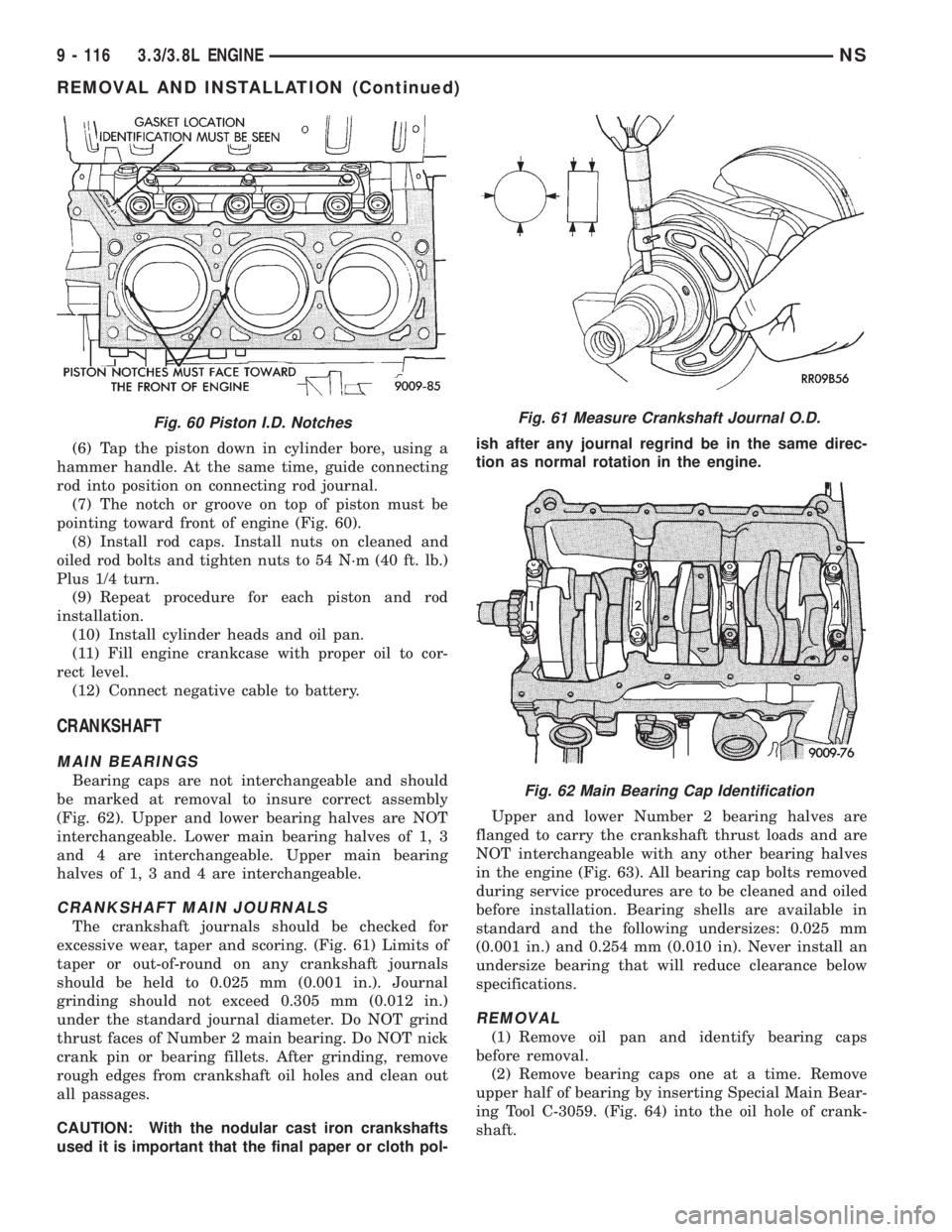
(6) Tap the piston down in cylinder bore, using a
hammer handle. At the same time, guide connecting
rod into position on connecting rod journal.
(7) The notch or groove on top of piston must be
pointing toward front of engine (Fig. 60).
(8) Install rod caps. Install nuts on cleaned and
oiled rod bolts and tighten nuts to 54 N´m (40 ft. lb.)
Plus 1/4 turn.
(9) Repeat procedure for each piston and rod
installation.
(10) Install cylinder heads and oil pan.
(11) Fill engine crankcase with proper oil to cor-
rect level.
(12) Connect negative cable to battery.
CRANKSHAFT
MAIN BEARINGS
Bearing caps are not interchangeable and should
be marked at removal to insure correct assembly
(Fig. 62). Upper and lower bearing halves are NOT
interchangeable. Lower main bearing halves of 1, 3
and 4 are interchangeable. Upper main bearing
halves of 1, 3 and 4 are interchangeable.
CRANKSHAFT MAIN JOURNALS
The crankshaft journals should be checked for
excessive wear, taper and scoring. (Fig. 61) Limits of
taper or out-of-round on any crankshaft journals
should be held to 0.025 mm (0.001 in.). Journal
grinding should not exceed 0.305 mm (0.012 in.)
under the standard journal diameter. Do NOT grind
thrust faces of Number 2 main bearing. Do NOT nick
crank pin or bearing fillets. After grinding, remove
rough edges from crankshaft oil holes and clean out
all passages.
CAUTION: With the nodular cast iron crankshafts
used it is important that the final paper or cloth pol-ish after any journal regrind be in the same direc-
tion as normal rotation in the engine.
Upper and lower Number 2 bearing halves are
flanged to carry the crankshaft thrust loads and are
NOT interchangeable with any other bearing halves
in the engine (Fig. 63). All bearing cap bolts removed
during service procedures are to be cleaned and oiled
before installation. Bearing shells are available in
standard and the following undersizes: 0.025 mm
(0.001 in.) and 0.254 mm (0.010 in). Never install an
undersize bearing that will reduce clearance below
specifications.
REMOVAL
(1) Remove oil pan and identify bearing caps
before removal.
(2) Remove bearing caps one at a time. Remove
upper half of bearing by inserting Special Main Bear-
ing Tool C-3059. (Fig. 64) into the oil hole of crank-
shaft.
Fig. 60 Piston I.D. NotchesFig. 61 Measure Crankshaft Journal O.D.
Fig. 62 Main Bearing Cap Identification
9 - 116 3.3/3.8L ENGINENS
REMOVAL AND INSTALLATION (Continued)
Page 1169 of 1938
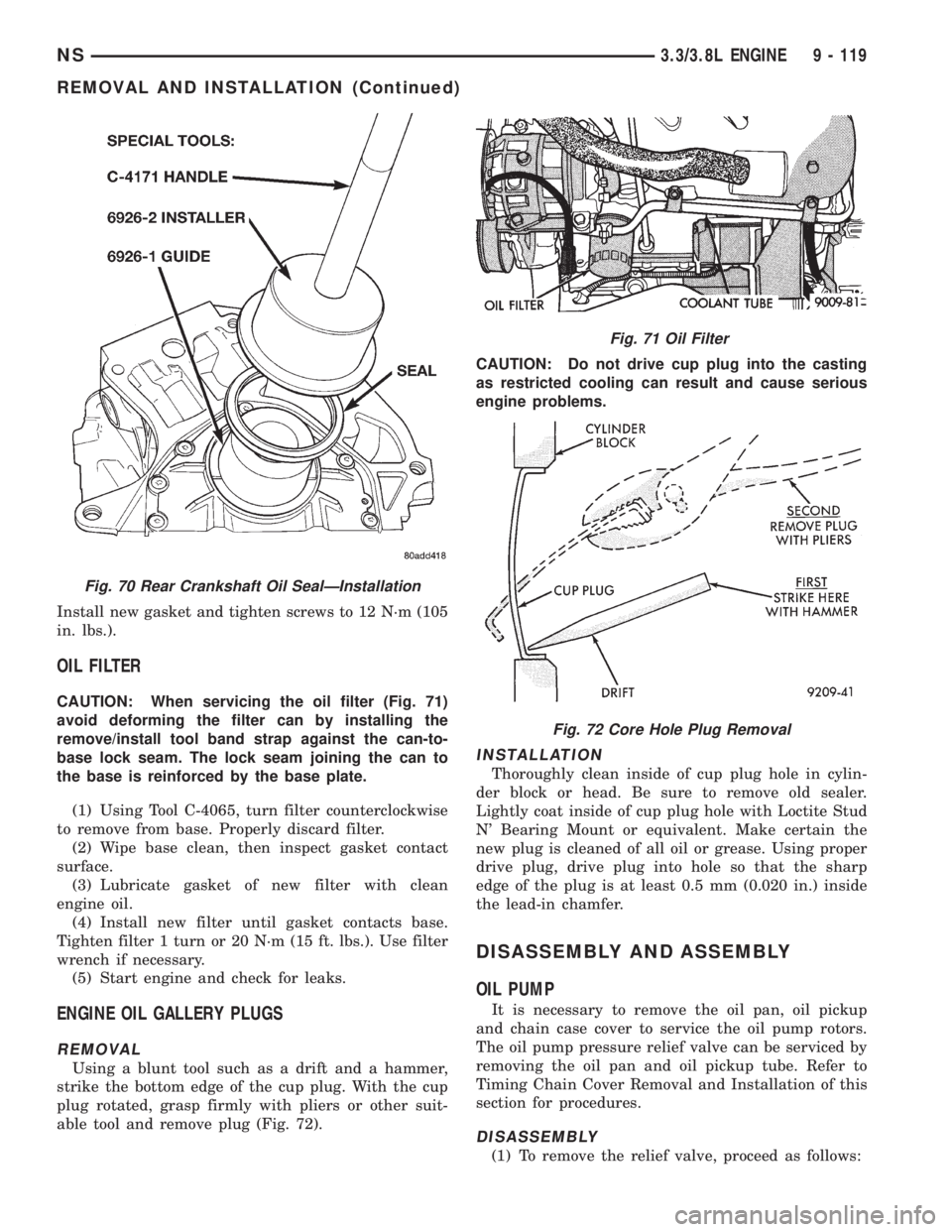
Install new gasket and tighten screws to 12 N´m (105
in. lbs.).
OIL FILTER
CAUTION: When servicing the oil filter (Fig. 71)
avoid deforming the filter can by installing the
remove/install tool band strap against the can-to-
base lock seam. The lock seam joining the can to
the base is reinforced by the base plate.
(1) Using Tool C-4065, turn filter counterclockwise
to remove from base. Properly discard filter.
(2) Wipe base clean, then inspect gasket contact
surface.
(3) Lubricate gasket of new filter with clean
engine oil.
(4) Install new filter until gasket contacts base.
Tighten filter 1 turn or 20 N´m (15 ft. lbs.). Use filter
wrench if necessary.
(5) Start engine and check for leaks.
ENGINE OIL GALLERY PLUGS
REMOVAL
Using a blunt tool such as a drift and a hammer,
strike the bottom edge of the cup plug. With the cup
plug rotated, grasp firmly with pliers or other suit-
able tool and remove plug (Fig. 72).CAUTION: Do not drive cup plug into the casting
as restricted cooling can result and cause serious
engine problems.
INSTALLATION
Thoroughly clean inside of cup plug hole in cylin-
der block or head. Be sure to remove old sealer.
Lightly coat inside of cup plug hole with Loctite Stud
N' Bearing Mount or equivalent. Make certain the
new plug is cleaned of all oil or grease. Using proper
drive plug, drive plug into hole so that the sharp
edge of the plug is at least 0.5 mm (0.020 in.) inside
the lead-in chamfer.
DISASSEMBLY AND ASSEMBLY
OIL PUMP
It is necessary to remove the oil pan, oil pickup
and chain case cover to service the oil pump rotors.
The oil pump pressure relief valve can be serviced by
removing the oil pan and oil pickup tube. Refer to
Timing Chain Cover Removal and Installation of this
section for procedures.
DISASSEMBLY
(1) To remove the relief valve, proceed as follows:
Fig. 70 Rear Crankshaft Oil SealÐInstallation
Fig. 71 Oil Filter
Fig. 72 Core Hole Plug Removal
NS3.3/3.8L ENGINE 9 - 119
REMOVAL AND INSTALLATION (Continued)
Page 1170 of 1938
(2) Drill a 3.175 mm (1/8 inch) hole into the relief
valve retainer cap and insert a self-threading sheet
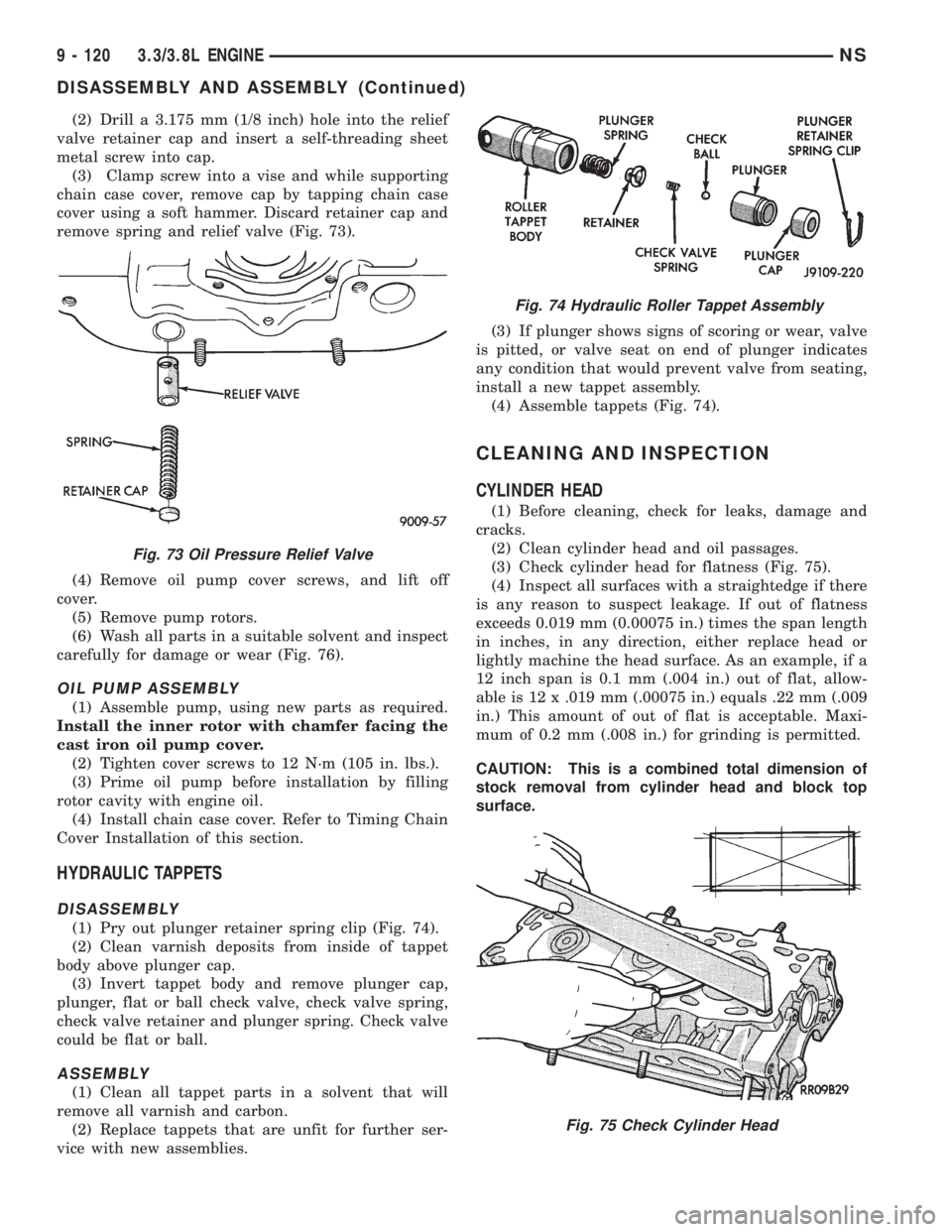
metal screw into cap.
(3) Clamp screw into a vise and while supporting
chain case cover, remove cap by tapping chain case
cover using a soft hammer. Discard retainer cap and
remove spring and relief valve (Fig. 73).
(4) Remove oil pump cover screws, and lift off
cover.
(5) Remove pump rotors.
(6) Wash all parts in a suitable solvent and inspect
carefully for damage or wear (Fig. 76).
OIL PUMP ASSEMBLY
(1) Assemble pump, using new parts as required.
Install the inner rotor with chamfer facing the
cast iron oil pump cover.
(2) Tighten cover screws to 12 N´m (105 in. lbs.).
(3) Prime oil pump before installation by filling
rotor cavity with engine oil.
(4) Install chain case cover. Refer to Timing Chain
Cover Installation of this section.
HYDRAULIC TAPPETS
DISASSEMBLY
(1) Pry out plunger retainer spring clip (Fig. 74).
(2) Clean varnish deposits from inside of tappet
body above plunger cap.
(3) Invert tappet body and remove plunger cap,
plunger, flat or ball check valve, check valve spring,
check valve retainer and plunger spring. Check valve
could be flat or ball.
ASSEMBLY
(1) Clean all tappet parts in a solvent that will
remove all varnish and carbon.
(2) Replace tappets that are unfit for further ser-
vice with new assemblies.(3) If plunger shows signs of scoring or wear, valve
is pitted, or valve seat on end of plunger indicates
any condition that would prevent valve from seating,
install a new tappet assembly.
(4) Assemble tappets (Fig. 74).
CLEANING AND INSPECTION
CYLINDER HEAD
(1) Before cleaning, check for leaks, damage and
cracks.
(2) Clean cylinder head and oil passages.
(3) Check cylinder head for flatness (Fig. 75).
(4) Inspect all surfaces with a straightedge if there
is any reason to suspect leakage. If out of flatness
exceeds 0.019 mm (0.00075 in.) times the span length
in inches, in any direction, either replace head or
lightly machine the head surface. As an example, if a
12 inch span is 0.1 mm (.004 in.) out of flat, allow-
able is 12 x .019 mm (.00075 in.) equals .22 mm (.009
in.) This amount of out of flat is acceptable. Maxi-
mum of 0.2 mm (.008 in.) for grinding is permitted.
CAUTION: This is a combined total dimension of
stock removal from cylinder head and block top
surface.
Fig. 73 Oil Pressure Relief Valve
Fig. 74 Hydraulic Roller Tappet Assembly
Fig. 75 Check Cylinder Head
9 - 120 3.3/3.8L ENGINENS
DISASSEMBLY AND ASSEMBLY (Continued)