check engine CHRYSLER VOYAGER 1996 Owners Manual
[x] Cancel search | Manufacturer: CHRYSLER, Model Year: 1996, Model line: VOYAGER, Model: CHRYSLER VOYAGER 1996Pages: 1938, PDF Size: 55.84 MB
Page 1079 of 1938
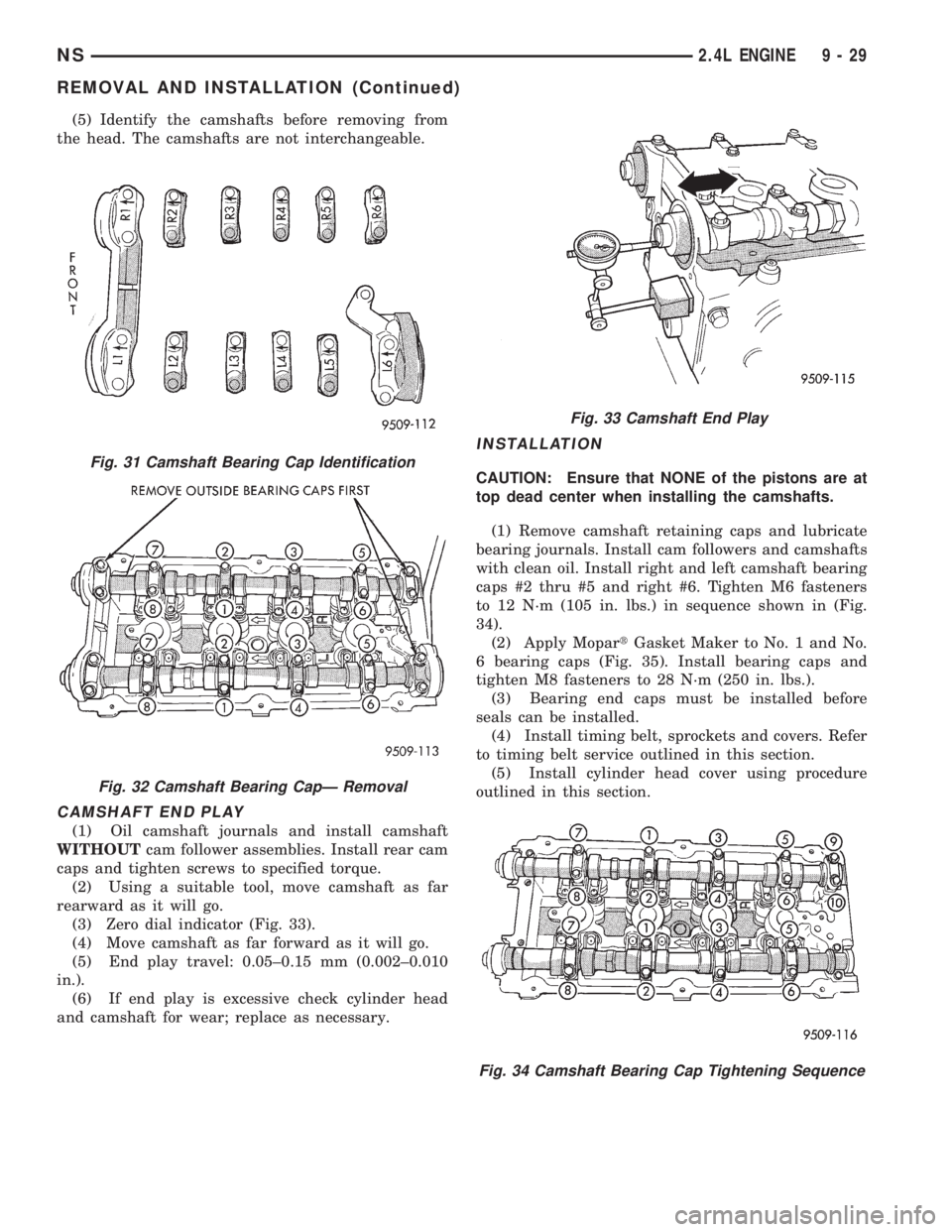
(5) Identify the camshafts before removing from
the head. The camshafts are not interchangeable.
CAMSHAFT END PLAY
(1) Oil camshaft journals and install camshaft
WITHOUTcam follower assemblies. Install rear cam
caps and tighten screws to specified torque.
(2) Using a suitable tool, move camshaft as far
rearward as it will go.
(3) Zero dial indicator (Fig. 33).
(4) Move camshaft as far forward as it will go.
(5) End play travel: 0.05±0.15 mm (0.002±0.010
in.).
(6) If end play is excessive check cylinder head
and camshaft for wear; replace as necessary.
INSTALLATION
CAUTION: Ensure that NONE of the pistons are at
top dead center when installing the camshafts.
(1) Remove camshaft retaining caps and lubricate
bearing journals. Install cam followers and camshafts
with clean oil. Install right and left camshaft bearing
caps #2 thru #5 and right #6. Tighten M6 fasteners
to 12 N´m (105 in. lbs.) in sequence shown in (Fig.
34).
(2) Apply MopartGasket Maker to No. 1 and No.
6 bearing caps (Fig. 35). Install bearing caps and
tighten M8 fasteners to 28 N´m (250 in. lbs.).
(3) Bearing end caps must be installed before
seals can be installed.
(4) Install timing belt, sprockets and covers. Refer
to timing belt service outlined in this section.
(5) Install cylinder head cover using procedure
outlined in this section.Fig. 31 Camshaft Bearing Cap Identification
Fig. 32 Camshaft Bearing CapÐ Removal
Fig. 33 Camshaft End Play
Fig. 34 Camshaft Bearing Cap Tightening Sequence
NS2.4L ENGINE 9 - 29
REMOVAL AND INSTALLATION (Continued)
Page 1084 of 1938
CYLINDER HEAD
REMOVAL
(1) Perform fuel system pressure release proce-
durebefore attempting any repairs.Refer to
Group 14, Fuel System for procedure.
(2) Disconnect negative battery cable. Drain cool-
ing system. Refer to Group 7, Cooling System for pro-
cedure.
(3) Remove air cleaner and disconnect all vacuum
lines, electrical wiring and fuel lines from throttle
body.
(4) Remove throttle linkage. Refer to Group 14,
Fuel System for procedures
(5) Remove accessory drive belts. Refer to Group
7, Cooling System for procedure.
(6) Remove power brake vacuum hose from intake
manifold.
(7) Raise vehicle and remove exhaust pipe from
manifold.(8) Remove power steering pump assembly and
set aside.
(9) Disconnect coil pack wiring connector and
remove coil pack and plug wires from engine.
(10) Remove cam sensor and fuel injectors wiring
connectors.
(11) Remove timing belt and camshaft sprocket.
Refer to procedure outlined in this section.
(12) Remove timing belt idler pulley and rear tim-
ing belt cover.
(13) Remove cylinder head cover using procedure
outlined in this section.
(14) Remove camshafts and cam followers. Refer to
procedures outlined in this section for procedures.
(15) Remove cylinder head bolts and remove cyl-
inder head from engine block.
(16) Inspect and clean cylinder head. Refer to
Cleaning and Inspection outlined in this section for
procedures.
INSTALLATION
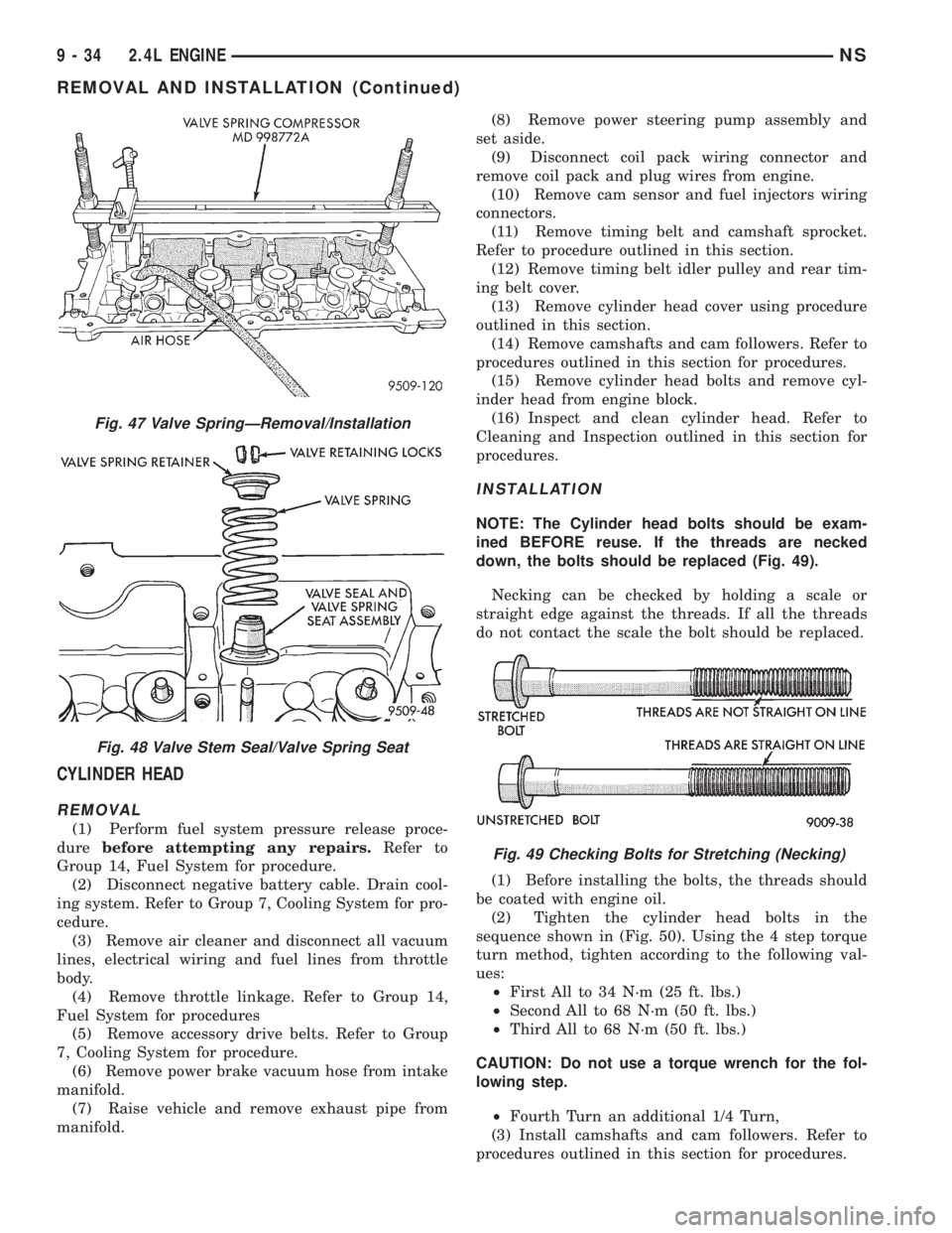
NOTE: The Cylinder head bolts should be exam-
ined BEFORE reuse. If the threads are necked
down, the bolts should be replaced (Fig. 49).
Necking can be checked by holding a scale or
straight edge against the threads. If all the threads
do not contact the scale the bolt should be replaced.
(1) Before installing the bolts, the threads should
be coated with engine oil.
(2) Tighten the cylinder head bolts in the
sequence shown in (Fig. 50). Using the 4 step torque
turn method, tighten according to the following val-
ues:
²First All to 34 N´m (25 ft. lbs.)
²Second All to 68 N´m (50 ft. lbs.)
²Third All to 68 N´m (50 ft. lbs.)
CAUTION: Do not use a torque wrench for the fol-
lowing step.
²Fourth Turn an additional 1/4 Turn,
(3) Install camshafts and cam followers. Refer to
procedures outlined in this section for procedures.
Fig. 47 Valve SpringÐRemoval/Installation
Fig. 48 Valve Stem Seal/Valve Spring Seat
Fig. 49 Checking Bolts for Stretching (Necking)
9 - 34 2.4L ENGINENS
REMOVAL AND INSTALLATION (Continued)
Page 1085 of 1938
(4) Install cylinder head cover using procedure out-
lined in this section.
(5) Install rear timing belt cover and timing belt
idler pulley.
(6) Install timing belt and camshaft sprocket.
Refer to procedure outlined in this section.
(7) Install cam sensor and fuel injectors wiring
connectors.
(8) Install coil pack and plug wires onto the
engine. Connect coil pack wiring connector.
(9) Install power steering pump assembly.
(10) Raise vehicle and install the exhaust pipe to
the manifold.
(11) Install power brake vacuum hose to the intake
manifold.
(12) Install accessory drive belts. Refer to Group 7,
Cooling System for procedure.
(13) Install throttle linkage. Refer to Group 14,
Fuel System for procedures.
(14) Install air cleaner and connect all vacuum
lines, electrical wiring and fuel lines to the throttle
body.
(15) Fill cooling system. Refer to Group 7, Cooling
System for procedure. Connect negative battery
cable.
VALVES AND VALVE SPRINGS
REMOVAL
(1) With cylinder head removed, compress valve
springs using a universal valve spring compressor.
(2) Remove valve retaining locks, valve spring
retainers, valve stem seals and valve springs.(3) Before removing valves,remove any burrs
from valve stem lock grooves to prevent dam-
age to the valve guides.Identify valves to insure
installation in original location.
(4) Inspect and clean the valves. Refer to Cleaning
and Inspection outlined in this section for procedure.
INSTALLATION
(1) Coat valve stems with clean engine oil and
insert in cylinder head.
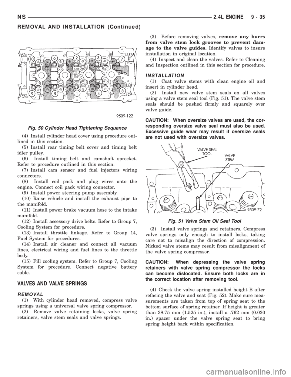
(2) Install new valve stem seals on all valves
using a valve stem seal tool (Fig. 51). The valve stem
seals should be pushed firmly and squarely over
valve guide.
CAUTION: When oversize valves are used, the cor-
responding oversize valve seal must also be used.
Excessive guide wear may result if oversize seals
are not used with oversize valves.
(3) Install valve springs and retainers. Compress
valve springs only enough to install locks, taking
care not to misalign the direction of compression.
Nicked valve stems may result from misalignment of
the valve spring compressor.
CAUTION: When depressing the valve spring
retainers with valve spring compressor the locks
can become dislocated. Ensure both locks are in
the correct location after removing tool.
(4) Check the valve spring installed height B after
refacing the valve and seat (Fig. 52). Make sure mea-
surements are taken from top of spring seat to the
bottom surface of spring retainer. If height is greater
than 38.75 mm (1.525 in.), install a .762 mm (0.030
in.) spacer under the valve spring seat to bring
spring height back within specification.
Fig. 50 Cylinder Head Tightening Sequence
Fig. 51 Valve Stem Oil Seal Tool
NS2.4L ENGINE 9 - 35
REMOVAL AND INSTALLATION (Continued)
Page 1086 of 1938
VIBRATION DAMPER
REMOVAL
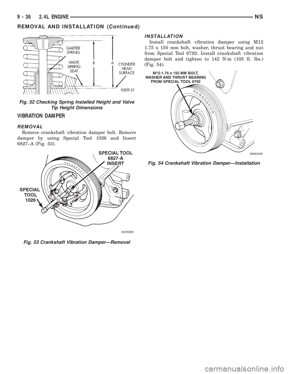
Remove crankshaft vibration damper bolt. Remove
damper by using Special Tool 1026 and Insert
6827±A (Fig. 53).
INSTALLATION
Install crankshaft vibration damper using M12
1.75 x 150 mm bolt, washer, thrust bearing and nut
from Special Tool 6792. Install crankshaft vibration
damper bolt and tighten to 142 N´m (105 ft. lbs.)
(Fig. 54).
Fig. 52 Checking Spring Installed Height and Valve
Tip Height Dimensions
Fig. 53 Crankshaft Vibration DamperÐRemoval
Fig. 54 Crankshaft Vibration DamperÐInstallation
9 - 36 2.4L ENGINENS
REMOVAL AND INSTALLATION (Continued)
Page 1097 of 1938
(7) Install main bearing bedplate to engine block
bolts 11, 17 and 20 finger tight. Tighten these bolts
down together until the bedplate contacts the cylin-
der block.
(8) To ensure correct thrust bearing alignment per-
form the following steps:
²Step 1: Rotate crankshaft until number 4 pis-
ton is at TDC.
²Step 2: Move crankshaft rearward to limits of
travel.
²Step 3: Then, move crankshaft forward to lim-
its of travel.
²Step 4: Wedge an appropraite tool between the
rear of the cylinder block(NOT BED PLATE)and
the rear crankshaft counterweight. This will hold the
crankshaft in it's furthest forward position.
²Step 5: Install and tighten bolts (1-10) in
sequence shown in (Fig. 84) to 41 Nzm (30 ft. lbs.).
²Step 6: Remove wedge tool used to hold crank-
shaft.
(9) Tighten bolts (1-10) again to 41 Nzm (30 ft. lbs)
+ 1/4 turn in sequence shown in (Fig. 84).
(10) Install main bearing bedplate to engine block
bolts (11-20), and torque each bolt to 28 Nzm (20 ft.
lbs.) in sequence shown in (Fig. 84).
(11) After the main bearing bedplate is installed,
check the crankshaft turning torque. The turning
torque should not exceed 5.6 Nzm (50 in. lbs.).
OIL FILTER
CAUTION: When servicing the oil filter avoid
deforming the filter can by installing the remove/in-
stall tool band strap against the can to base lock
seam. The lock seam joining the can to the base is
reinforced by the base plate.(1) Turn counterclockwise to remove.
(2) To install, lubricate new filter gasket. Check
filter mounting surface. The surface must be smooth,
flat and free of debris or old pieces of rubber. Screw
filter on until the gasket contacts base. Tighten to 21
N´m (15 ft. lbs.).
OIL PUMP
REMOVAL
(1) Disconnect negative cable from battery.
(2) Remove Timing Belt. Refer to procedure out-
lined in this section.
(3) Remove Oil Pan. Refer to procedure outlined in
this section.
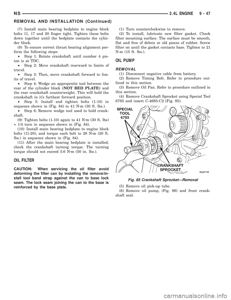
(4) Remove Crankshaft Sprocket using Special Tool
6793 and insert C-4685-C2 (Fig. 85).
(5) Remove oil pick-up tube.
(6) Remove oil pump, (Fig. 86) and front crank-
shaft seal.
Fig. 85 Crankshaft SprocketÐRemoval
NS2.4L ENGINE 9 - 47
REMOVAL AND INSTALLATION (Continued)
Page 1100 of 1938
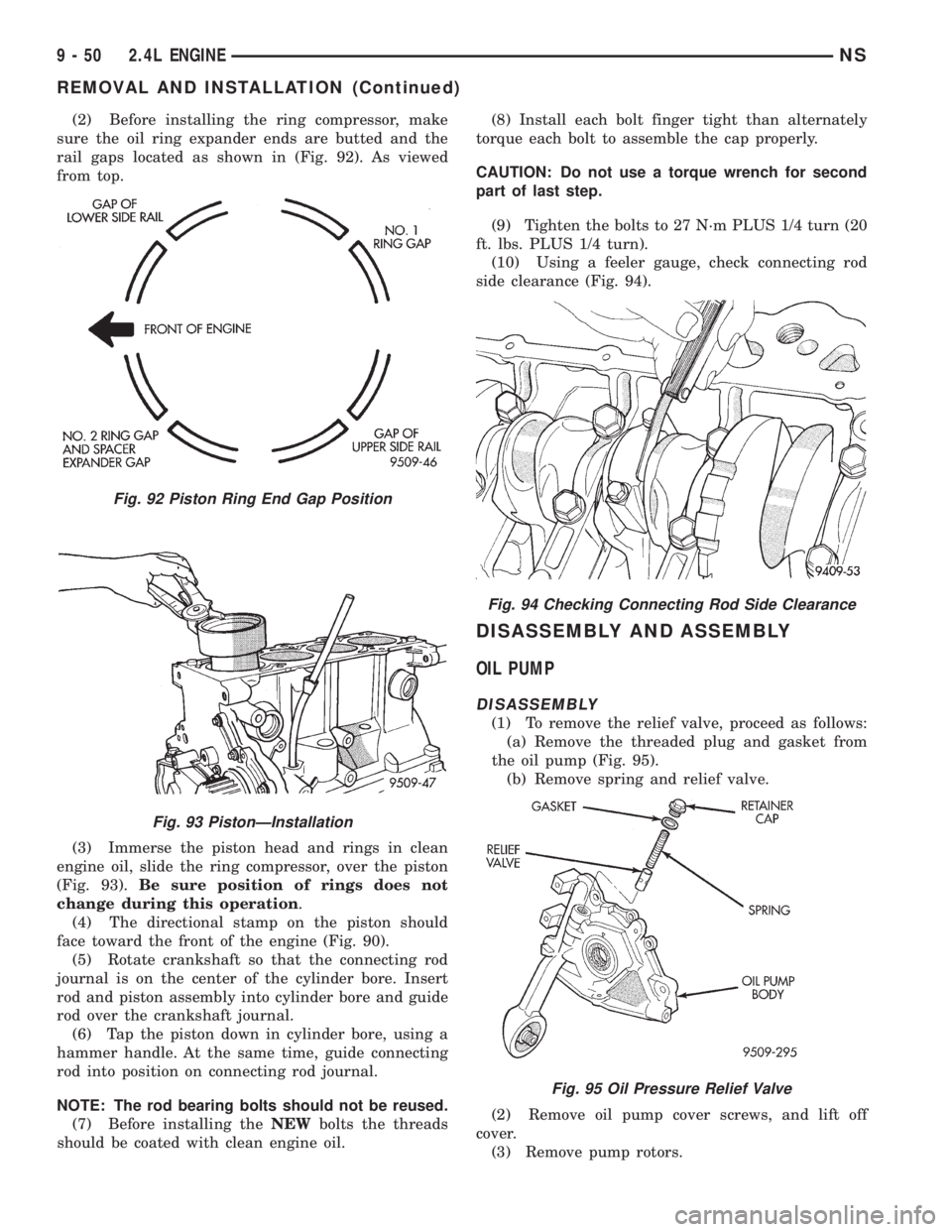
(2) Before installing the ring compressor, make
sure the oil ring expander ends are butted and the
rail gaps located as shown in (Fig. 92). As viewed
from top.
(3) Immerse the piston head and rings in clean
engine oil, slide the ring compressor, over the piston
(Fig. 93).Be sure position of rings does not
change during this operation.
(4) The directional stamp on the piston should
face toward the front of the engine (Fig. 90).
(5) Rotate crankshaft so that the connecting rod
journal is on the center of the cylinder bore. Insert
rod and piston assembly into cylinder bore and guide
rod over the crankshaft journal.
(6) Tap the piston down in cylinder bore, using a
hammer handle. At the same time, guide connecting
rod into position on connecting rod journal.
NOTE: The rod bearing bolts should not be reused.
(7) Before installing theNEWbolts the threads
should be coated with clean engine oil.(8) Install each bolt finger tight than alternately
torque each bolt to assemble the cap properly.
CAUTION: Do not use a torque wrench for second
part of last step.
(9) Tighten the bolts to 27 N´m PLUS 1/4 turn (20
ft. lbs. PLUS 1/4 turn).
(10) Using a feeler gauge, check connecting rod
side clearance (Fig. 94).
DISASSEMBLY AND ASSEMBLY
OIL PUMP
DISASSEMBLY
(1) To remove the relief valve, proceed as follows:
(a) Remove the threaded plug and gasket from
the oil pump (Fig. 95).
(b) Remove spring and relief valve.
(2) Remove oil pump cover screws, and lift off
cover.
(3) Remove pump rotors.
Fig. 92 Piston Ring End Gap Position
Fig. 93 PistonÐInstallation
Fig. 94 Checking Connecting Rod Side Clearance
Fig. 95 Oil Pressure Relief Valve
9 - 50 2.4L ENGINENS
REMOVAL AND INSTALLATION (Continued)
Page 1101 of 1938
(4) Wash all parts in a suitable solvent and
inspect carefully for damage or wear.
ASSEMBLY
(1) Assemble pump, using new parts as required.
Install the inner rotor with chamfer facing the
cast iron oil pump cover.
(2) Prime oil pump before installation by filling
rotor cavity with engine oil.
(3) Install cover and tighten screws to 12 N´m
(105 in. lbs.).
CAUTION: Oil pump pressure relief valve must be
installed as shown in (Fig. 95) or serious damage
may occur.
(4) Install relief valve, spring, gasket and cap as
shown in (Fig. 95). Tighten cap to 41 N´m (30 ft. lbs.)
CLEANING AND INSPECTION
CYLINDER HEAD
CLEANING
Remove all gasket material from cylinder head and
block. Be careful not to gouge or scratch the alumi-
num head sealing surface.
INSPECTION
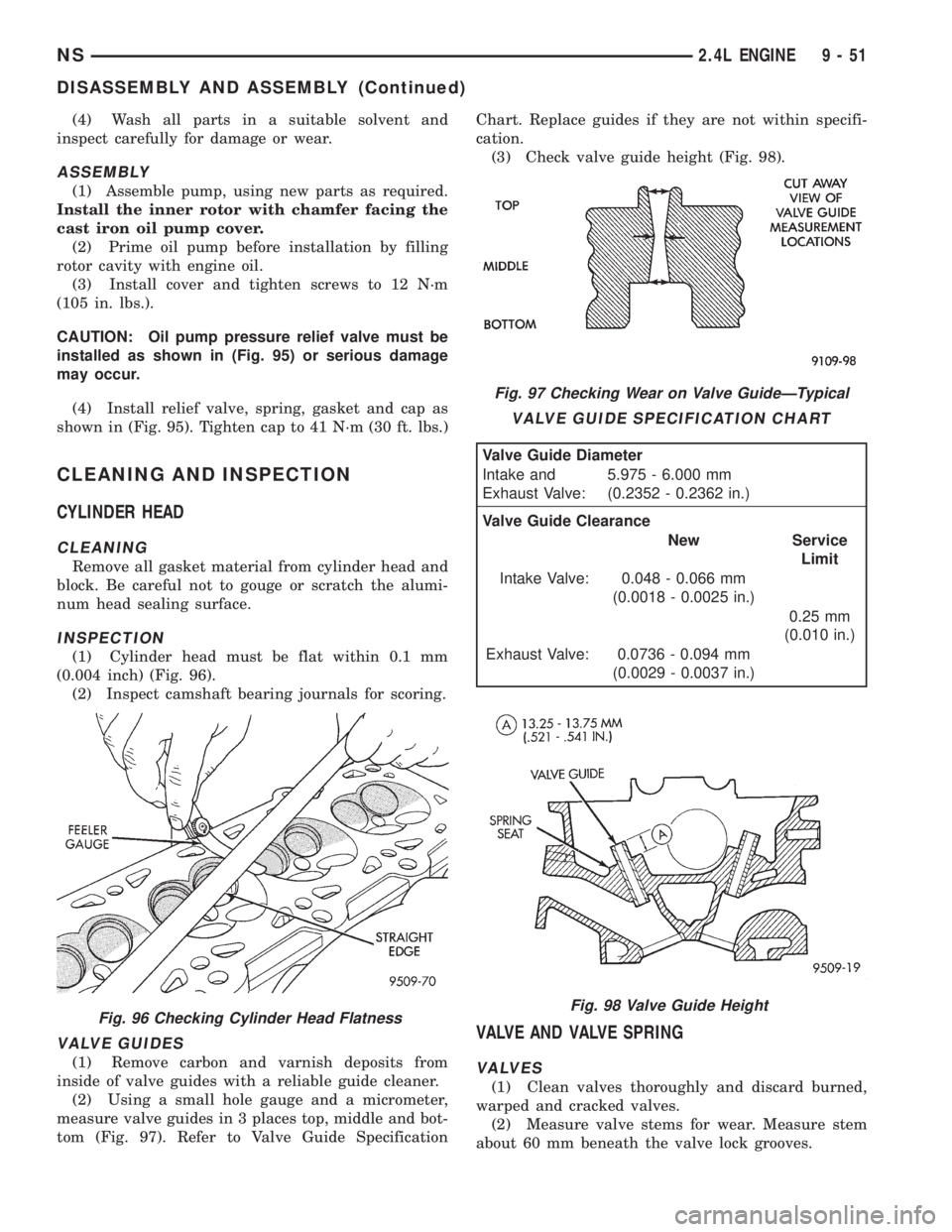
(1) Cylinder head must be flat within 0.1 mm
(0.004 inch) (Fig. 96).
(2) Inspect camshaft bearing journals for scoring.
VALVE GUIDES
(1) Remove carbon and varnish deposits from
inside of valve guides with a reliable guide cleaner.
(2) Using a small hole gauge and a micrometer,
measure valve guides in 3 places top, middle and bot-
tom (Fig. 97). Refer to Valve Guide SpecificationChart. Replace guides if they are not within specifi-
cation.
(3) Check valve guide height (Fig. 98).
VALVE AND VALVE SPRING
VALVES
(1) Clean valves thoroughly and discard burned,
warped and cracked valves.
(2) Measure valve stems for wear. Measure stem
about 60 mm beneath the valve lock grooves.
Fig. 96 Checking Cylinder Head Flatness
Fig. 97 Checking Wear on Valve GuideÐTypical
VALVE GUIDE SPECIFICATION CHART
Valve Guide Diameter
Intake and
Exhaust Valve:5.975 - 6.000 mm
(0.2352 - 0.2362 in.)
Valve Guide Clearance
New Service
Limit
Intake Valve: 0.048 - 0.066 mm
(0.0018 - 0.0025 in.)
0.25 mm
(0.010 in.)
Exhaust Valve: 0.0736 - 0.094 mm
(0.0029 - 0.0037 in.)
Fig. 98 Valve Guide Height
NS2.4L ENGINE 9 - 51
DISASSEMBLY AND ASSEMBLY (Continued)
Page 1102 of 1938
(3) If valve stems are worn more than 0.05 mm
(.002 in.), replace valve.
VALVE SPRINGS
(1) Whenever valves have been removed for
inspection, reconditioning or replacement, valve
springs should be tested for correct tension. Discard
the springs that do not meet specifications. The fol-
lowing specifications apply to both intake and
exhaust valves springs:
²Valve Closed Nominal TensionÐ 76 lbs. @ 38.0
mm (1.50 in.)
²Valve Open Nominal TensionÐ 136 lbs. @ 29.75
mm (1.17 in.)
(2) Inspect each valve spring for squareness with
a steel square and surface plate, test springs from
both ends. If the spring is more than 1.5 mm (1/16
inch) out of square, install a new spring.
CRANKSHAFT
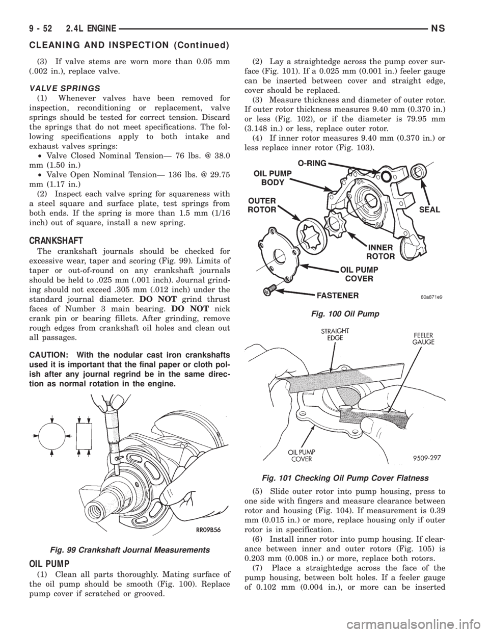
The crankshaft journals should be checked for
excessive wear, taper and scoring (Fig. 99). Limits of
taper or out-of-round on any crankshaft journals
should be held to .025 mm (.001 inch). Journal grind-
ing should not exceed .305 mm (.012 inch) under the
standard journal diameter.DO NOTgrind thrust
faces of Number 3 main bearing.DO NOTnick
crank pin or bearing fillets. After grinding, remove
rough edges from crankshaft oil holes and clean out
all passages.
CAUTION: With the nodular cast iron crankshafts
used it is important that the final paper or cloth pol-
ish after any journal regrind be in the same direc-
tion as normal rotation in the engine.
OIL PUMP
(1) Clean all parts thoroughly. Mating surface of
the oil pump should be smooth (Fig. 100). Replace
pump cover if scratched or grooved.(2) Lay a straightedge across the pump cover sur-
face (Fig. 101). If a 0.025 mm (0.001 in.) feeler gauge
can be inserted between cover and straight edge,
cover should be replaced.
(3) Measure thickness and diameter of outer rotor.
If outer rotor thickness measures 9.40 mm (0.370 in.)
or less (Fig. 102), or if the diameter is 79.95 mm
(3.148 in.) or less, replace outer rotor.
(4) If inner rotor measures 9.40 mm (0.370 in.) or
less replace inner rotor (Fig. 103).
(5) Slide outer rotor into pump housing, press to
one side with fingers and measure clearance between
rotor and housing (Fig. 104). If measurement is 0.39
mm (0.015 in.) or more, replace housing only if outer
rotor is in specification.
(6) Install inner rotor into pump housing. If clear-
ance between inner and outer rotors (Fig. 105) is
0.203 mm (0.008 in.) or more, replace both rotors.
(7) Place a straightedge across the face of the
pump housing, between bolt holes. If a feeler gauge
of 0.102 mm (0.004 in.), or more can be inserted
Fig. 99 Crankshaft Journal Measurements
Fig. 100 Oil Pump
Fig. 101 Checking Oil Pump Cover Flatness
9 - 52 2.4L ENGINENS
CLEANING AND INSPECTION (Continued)
Page 1104 of 1938
CYLINDER BLOCK
(1) Clean cylinder block thoroughly and check all
core hole plugs for evidence of leaking.
(2) If new core plugs are installed, refer to Engine
Core Plugs outlined in this section.
(3) Examine block and cylinder bores for cracks or
fractures.
CYLINDER BORE INSPECTION
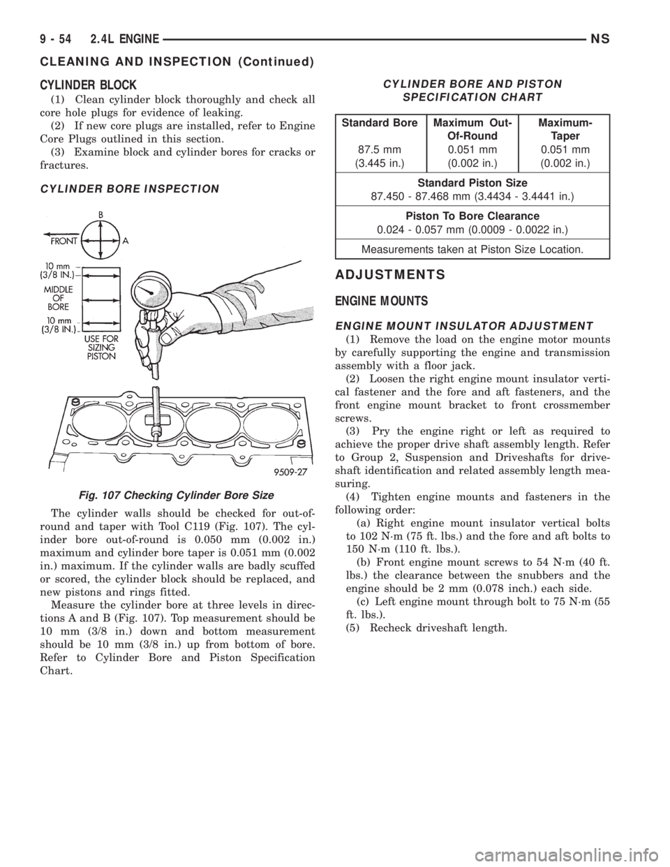
The cylinder walls should be checked for out-of-
round and taper with Tool C119 (Fig. 107). The cyl-
inder bore out-of-round is 0.050 mm (0.002 in.)
maximum and cylinder bore taper is 0.051 mm (0.002
in.) maximum. If the cylinder walls are badly scuffed
or scored, the cylinder block should be replaced, and
new pistons and rings fitted.
Measure the cylinder bore at three levels in direc-
tions A and B (Fig. 107). Top measurement should be
10 mm (3/8 in.) down and bottom measurement
should be 10 mm (3/8 in.) up from bottom of bore.
Refer to Cylinder Bore and Piston Specification
Chart.
ADJUSTMENTS
ENGINE MOUNTS
ENGINE MOUNT INSULATOR ADJUSTMENT
(1) Remove the load on the engine motor mounts
by carefully supporting the engine and transmission
assembly with a floor jack.
(2) Loosen the right engine mount insulator verti-
cal fastener and the fore and aft fasteners, and the
front engine mount bracket to front crossmember
screws.
(3) Pry the engine right or left as required to
achieve the proper drive shaft assembly length. Refer
to Group 2, Suspension and Driveshafts for drive-
shaft identification and related assembly length mea-
suring.
(4) Tighten engine mounts and fasteners in the
following order:
(a) Right engine mount insulator vertical bolts
to 102 N´m (75 ft. lbs.) and the fore and aft bolts to
150 N´m (110 ft. lbs.).
(b) Front engine mount screws to 54 N´m (40 ft.
lbs.) the clearance between the snubbers and the
engine should be 2 mm (0.078 inch.) each side.
(c) Left engine mount through bolt to 75 N´m (55
ft. lbs.).
(5) Recheck driveshaft length.
Fig. 107 Checking Cylinder Bore Size
CYLINDER BORE AND PISTON
SPECIFICATION CHART
Standard Bore Maximum Out-
Of-RoundMaximum-
Taper
87.5 mm 0.051 mm 0.051 mm
(3.445 in.) (0.002 in.) (0.002 in.)
Standard Piston Size
87.450 - 87.468 mm (3.4434 - 3.4441 in.)
Piston To Bore Clearance
0.024 - 0.057 mm (0.0009 - 0.0022 in.)
Measurements taken at Piston Size Location.
9 - 54 2.4L ENGINENS
CLEANING AND INSPECTION (Continued)
Page 1111 of 1938
3.0L ENGINE
INDEX
page page
DESCRIPTION AND OPERATION
ENGINE COMPONENTS.................. 61
ENGINE IDENTIFICATION NUMBER......... 61
ENGINE LUBRICATION................... 61
DIAGNOSIS AND TESTING
CHECKING ENGINE OIL PRESSURE......... 62
SERVICE PROCEDURES
AUTO LASH ADJUSTER................... 62
CHECKING CRANKSHAFT END PLAY........ 65
FITTING CONNECTING ROD BEARINGS...... 63
FITTING MAIN BEARING.................. 63
VALVE SERVICE RECONDITION............ 66
REMOVAL AND INSTALLATION
CAMSHAFT SEAL....................... 72
CAMSHAFT............................ 71
CRANKSHAFT.......................... 81
CYLINDER HEAD COVER................. 70
CYLINDER HEAD........................ 73
ENGINE ASSEMBLY...................... 69
ENGINE MOUNTS....................... 68
FRONT CRANKSHAFT OIL SEAL............ 83OIL FILTER AND ADAPTOR................ 84
OILPAN ............................... 77
OIL PUMP............................. 84
PISTON AND CONNECTING ROD........... 78
REAR CRANKSHAFT SEAL................ 83
ROCKER ARMS......................... 72
TIMING BELT........................... 75
DISASSEMBLY AND ASSEMBLY
ROCKER ARMS AND SHAFTS.............. 85
CLEANING AND INSPECTION
CYLINDER BORE........................ 87
CYLINDER HEAD........................ 86
OIL PUMP............................. 87
TIMING BELT........................... 86
ADJUSTMENTS
ENGINE MOUNTS....................... 88
SPECIFICATIONS
3.0L ENGINE........................... 89
TORQUE CHART 3.0L.................... 90
SPECIAL TOOLS
3.0L ENGINE........................... 91
DESCRIPTION AND OPERATION
ENGINE IDENTIFICATION NUMBER
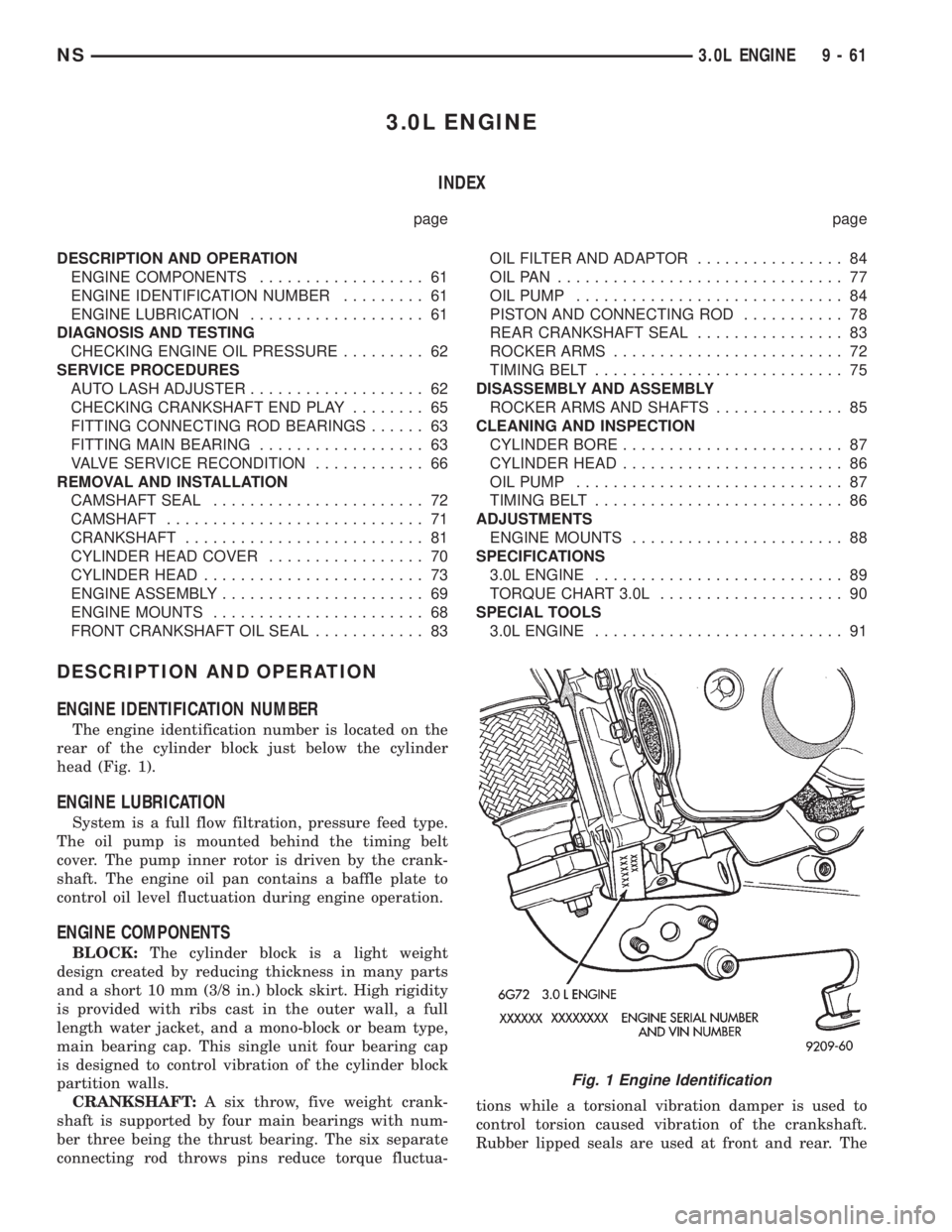
The engine identification number is located on the
rear of the cylinder block just below the cylinder
head (Fig. 1).
ENGINE LUBRICATION
System is a full flow filtration, pressure feed type.
The oil pump is mounted behind the timing belt
cover. The pump inner rotor is driven by the crank-
shaft. The engine oil pan contains a baffle plate to
control oil level fluctuation during engine operation.
ENGINE COMPONENTS
BLOCK:The cylinder block is a light weight
design created by reducing thickness in many parts
and a short 10 mm (3/8 in.) block skirt. High rigidity
is provided with ribs cast in the outer wall, a full
length water jacket, and a mono-block or beam type,
main bearing cap. This single unit four bearing cap
is designed to control vibration of the cylinder block
partition walls.
CRANKSHAFT:A six throw, five weight crank-
shaft is supported by four main bearings with num-
ber three being the thrust bearing. The six separate
connecting rod throws pins reduce torque fluctua-tions while a torsional vibration damper is used to
control torsion caused vibration of the crankshaft.
Rubber lipped seals are used at front and rear. The
Fig. 1 Engine Identification
NS3.0L ENGINE 9 - 61